---
title: Cloudflare WAN
description: Cloudflare WAN (formerly Magic WAN) connects your data centers, offices, and cloud resources through Cloudflare's global network. Instead of backhauling traffic through a central data center or maintaining dedicated MPLS circuits at every site, your traffic routes through the nearest Cloudflare data center where security policies apply inline.
image: https://developers.cloudflare.com/zt-preview.png
---
[Skip to content](#%5Ftop)
Was this helpful?
YesNo
[ Edit page ](https://github.com/cloudflare/cloudflare-docs/edit/production/src/content/docs/cloudflare-wan/index.mdx) [ Report issue ](https://github.com/cloudflare/cloudflare-docs/issues/new/choose)
Copy page
# Cloudflare WAN
Connect and secure your entire corporate network through Cloudflare, replacing MPLS circuits and hub-and-spoke routing with cloud-native networking.
Enterprise-only
Cloudflare WAN (formerly Magic WAN) connects your data centers, offices, and cloud resources through Cloudflare's global network. Instead of backhauling traffic through a central data center or maintaining dedicated MPLS circuits at every site, your traffic routes through the nearest Cloudflare data center where security policies apply inline.
Cloudflare WAN provides secure, performant [routing ↗](https://www.cloudflare.com/learning/network-layer/what-is-routing/) for your entire corporate network. [Cloudflare Network Firewall](https://developers.cloudflare.com/cloudflare-network-firewall/) integrates with Cloudflare WAN, enabling you to enforce network firewall policies at Cloudflare's global network, across traffic from any entity within your network.
You connect your sites to Cloudflare through on-ramps — tunnels or direct connections from your network to Cloudflare. Cloudflare WAN supports any device that uses anycast GRE or IPsec tunnels. To make it easier to onboard your cloud resources, you can use [Multi-Cloud Networking](https://developers.cloudflare.com/cloudflare-wan/configuration/multi-cloud-networking/), which automates creating on-ramps from your cloud networks. Refer to [On-ramps](https://developers.cloudflare.com/cloudflare-wan/on-ramps/) for a full list of supported on-ramps.
Refer to [WAN transformation](https://developers.cloudflare.com/cloudflare-wan/wan-transformation/) to compare approaches and plan your migration, or go straight to [get started](https://developers.cloudflare.com/cloudflare-wan/get-started/).
## Cloudflare WAN and Cloudflare One
Cloudflare WAN is a standalone WAN-as-a-Service (WANaaS) product. It provides site-to-site connectivity over Cloudflare's global network, with packet-level security through [Cloudflare Network Firewall](https://developers.cloudflare.com/cloudflare-network-firewall/). Cloudflare WAN supports IPsec tunnels, GRE tunnels, [Cloudflare Network Interconnect](https://developers.cloudflare.com/network-interconnect/), and the [Cloudflare One Appliance](https://developers.cloudflare.com/cloudflare-wan/configuration/appliance/) for connecting your sites.
[Cloudflare One](https://developers.cloudflare.com/cloudflare-one/) is the full SASE (Secure Access Service Edge) platform. It extends Cloudflare WAN with identity-aware security services:
* **[Cloudflare One Client (WARP)](https://developers.cloudflare.com/cloudflare-one/team-and-resources/devices/cloudflare-one-client/)** — deploys on user devices to route traffic through Cloudflare with identity context.
* **[Cloudflare Tunnel](https://developers.cloudflare.com/cloudflare-one/networks/connectors/cloudflare-tunnel/)** — creates outbound-only connections from your infrastructure to Cloudflare, with no inbound ports required.
* **[Cloudflare Gateway](https://developers.cloudflare.com/cloudflare-one/traffic-policies/)** — applies secure web gateway (SWG) policies to filter and inspect Internet-bound traffic.
* **[Cloudflare Access](https://developers.cloudflare.com/cloudflare-one/access-controls/)** — enforces Zero Trust Network Access (ZTNA) policies based on user identity, device posture, and context.
If your requirements are limited to site-to-site connectivity and network-layer security, Cloudflare WAN provides what you need. When you need user-level security policies, identity-based access controls, or secure Internet egress, you can add Cloudflare One capabilities to your existing deployment.
Cloudflare One builds on the same network infrastructure as Cloudflare WAN, so there is no migration required.
For more information about Cloudflare One, refer to the [Cloudflare One documentation](https://developers.cloudflare.com/cloudflare-one/).
---
## Features
### Connect your network automatically
Use Cloudflare One Appliance to automatically connect, steer, and shape any IP traffic.
[ Use Cloudflare One Appliance ](https://developers.cloudflare.com/cloudflare-wan/configuration/appliance/)
### Connect your network manually
Set up Cloudflare WAN with your existing routers and firewalls. If you do not have Cloudflare One Appliance, start here to configure IPsec or GRE tunnels from a third-party device.
[ Use a third-party device ](https://developers.cloudflare.com/cloudflare-wan/configuration/manually/third-party/)
### Automatic cloud on-ramps
Automate resource discovery, and reduce management burden when connecting to your public cloud.
[ Automate your cloud on-ramps ](https://developers.cloudflare.com/cloudflare-wan/configuration/multi-cloud-networking/)
### Zero Trust integration
Learn how you can use Cloudflare WAN with other Cloudflare Zero Trust products.
[ Integrate with other Zero Trust products ](https://developers.cloudflare.com/cloudflare-wan/zero-trust/)
### BGP peering (beta)
Use Border Gateway Protocol (BGP) peering between your networks and Cloudflare to automatically announce and withdraw routes as your network changes, rather than managing static routes manually.
[ Use BGP peering (beta) ](https://developers.cloudflare.com/cloudflare-wan/configuration/manually/how-to/configure-routes/#configure-bgp-routes)
### WAN transformation
Replace MPLS circuits and hub-and-spoke routing with cloud-native networking. Compare WAN approaches and plan an incremental migration.
[ Plan your migration ](https://developers.cloudflare.com/cloudflare-wan/wan-transformation/)
---
## Related products
**[Cloudflare One](https://developers.cloudflare.com/cloudflare-one/)** Cloudflare One is the full SASE platform. It extends Cloudflare WAN with identity-based access controls, secure web gateway policies, and user-level security for remote and hybrid workers.
**[Cloudflare Network Firewall](https://developers.cloudflare.com/cloudflare-network-firewall/)**
Cloudflare Network Firewall is a firewall-as-a-service (FWaaS) that filters traffic at layers 3 and 4 across Cloudflare's global network. Included with Cloudflare WAN.
**[Multi-Cloud Networking](https://developers.cloudflare.com/multi-cloud-networking/)** Simplify and automate cloud resource discovery, and reduce your management burden when connecting to your public cloud.
**[Cloudflare Network Interconnect](https://developers.cloudflare.com/network-interconnect/)**
Cloudflare Network Interconnect (CNI) provides a private, dedicated connection between your network and Cloudflare instead of routing over the public Internet. Use CNI when you need lower latency or more consistent performance than tunnel-based connectivity.
**[Load Balancing](https://developers.cloudflare.com/load-balancing/)**
Cloudflare Load Balancing distributes traffic across your endpoints, which reduces endpoint strain and latency and improves the experience for end users.
---
## More resources
[Reference Architecture](https://developers.cloudflare.com/reference-architecture/architectures/sase/)
Explore the architecture of Cloudflare One as a SASE platform, including how Cloudflare WAN handles connectivity, routing, and security.
```json
{"@context":"https://schema.org","@type":"BreadcrumbList","itemListElement":[{"@type":"ListItem","position":1,"item":{"@id":"/directory/","name":"Directory"}},{"@type":"ListItem","position":2,"item":{"@id":"/cloudflare-wan/","name":"Cloudflare WAN"}}]}
```
---
---
title: WAN transformation
description: Traditional wide area networks (WANs) were designed for a world where applications ran in corporate data centers and employees worked from offices. These architectures rely on private circuits like Multiprotocol Label Switching (MPLS), hub-and-spoke routing through central data centers, and dedicated hardware at every branch.
image: https://developers.cloudflare.com/zt-preview.png
---
[Skip to content](#%5Ftop)
Was this helpful?
YesNo
[ Edit page ](https://github.com/cloudflare/cloudflare-docs/edit/production/src/content/docs/cloudflare-wan/wan-transformation.mdx) [ Report issue ](https://github.com/cloudflare/cloudflare-docs/issues/new/choose)
Copy page
# WAN transformation
Traditional wide area networks (WANs) were designed for a world where applications ran in corporate data centers and employees worked from offices. These architectures rely on private circuits like Multiprotocol Label Switching (MPLS), hub-and-spoke routing through central data centers, and dedicated hardware at every branch.
As organizations adopt cloud services and support remote work, this model creates bottlenecks. Backhauling traffic to a central data center adds latency for cloud-bound traffic, and branch hardware requires ongoing maintenance and capital investment. WAN transformation replaces this architecture with cloud-native networking — routing traffic through a distributed global network instead of private circuits, and applying security inline rather than at a central chokepoint.
With Cloudflare One, your corporate WAN runs over Cloudflare's global network. You connect sites through anycast IPsec or GRE tunnels, and Cloudflare handles routing, security inspection, and traffic optimization at the nearest point of presence.
## Why transform your WAN
### Reduce cost and rigidity
MPLS circuits require multi-year contracts and take weeks or months to provision. Adding a new site means ordering a new circuit. Cloudflare One uses standard Internet circuits with anycast tunnels — you can connect a new site in minutes using any Internet connection and any device that supports IPsec or GRE.
### Eliminate Internet breakout tradeoffs
With traditional WANs, you have two options for Internet-bound traffic: backhaul it to a central data center for security inspection (adding latency), or break out directly at the branch (bypassing security controls). Cloudflare One eliminates this tradeoff. Traffic from every site reaches the nearest Cloudflare data center, where security policies are applied without the backhaul penalty.
### Avoid vendor lock-in
Proprietary SD-WAN appliances create dependency on a single vendor's hardware and software ecosystem. Cloudflare One uses open standards — IPsec, GRE, and BGP — and works with your existing third-party routers and firewalls. You can also use the [Cloudflare One Appliance](https://developers.cloudflare.com/cloudflare-wan/configuration/appliance/) for zero-touch provisioning at branch sites.
### Simplify operations
On-premises network and security appliances require manual firmware updates, patching, and capacity planning at every location. With Cloudflare One, networking and security services run in the cloud. Cloudflare manages updates and scaling globally, reducing the operational burden on your team.
## Compare WAN approaches
| Traditional WAN (MPLS) | SD-WAN | Cloudflare One | |
| ---------------------- | ----------------------------------------------------------------------------------------------------- | -------------------------------------------------------------------------------------------------- | ---------------------------------------------------------------------------------------------------------------- |
| **Performance** | Predictable but limited to circuit capacity. High latency for cloud-bound traffic due to backhauling. | Improved path selection across multiple links. Still relies on branch appliances for processing. | Traffic routed to the nearest Cloudflare data center. Cloud-bound traffic egresses locally without backhauling. |
| **Cost model** | High fixed costs. Multi-year contracts for private circuits. Per-site hardware investment. | Lower circuit costs (uses Internet links). Per-site appliance licensing and hardware costs remain. | Internet circuit costs only. No per-site hardware required (optional). Pay-as-you-grow model. |
| **Agility** | Weeks to months to provision new circuits. Rigid topology changes. | Faster site deployment over Internet circuits. Still requires appliance staging and configuration. | Connect a new site in minutes. Tunnels auto-establish from any Internet connection. |
| **Security** | Security applied at central data center or per-site firewalls. | Varies by vendor. Some offer integrated security, others require separate appliances. | Integrated security at every data center — firewall, secure web gateway, and Zero Trust policies applied inline. |
| **Management** | Separate management for WAN circuits, routers, and security appliances. | Single console for WAN, but security often managed separately. | Single dashboard for network connectivity, routing, firewall rules, and security policies. |
## Plan your migration
WAN transformation is not an all-or-nothing change. Most organizations follow an incremental approach, adding capabilities over time while decommissioning legacy infrastructure as each phase proves out.
### 1\. Secure user access
Start by replacing VPN concentrators with Zero Trust Network Access (ZTNA). Deploy the Cloudflare One Client on user devices and use Cloudflare Access to enforce identity-based policies for application access. This step secures remote and hybrid workers without changing your existing network infrastructure.
For more information, refer to [Cloudflare One](https://developers.cloudflare.com/cloudflare-wan/zero-trust/).
### 2\. Connect your networks
Set up site-to-site connectivity by establishing IPsec or GRE tunnels from your existing routers, deploying the Cloudflare One Appliance at branch locations, or using Cloudflare Network Interconnect for private connectivity. Your sites communicate through Cloudflare's network, and you manage routing through the dashboard or API.
* [Get started](https://developers.cloudflare.com/cloudflare-wan/get-started/) with Cloudflare WAN
* Review [connectivity options](https://developers.cloudflare.com/cloudflare-wan/zero-trust/connectivity-options/) to choose the right on-ramp
* Explore all available [on-ramps](https://developers.cloudflare.com/cloudflare-wan/on-ramps/)
### 3\. Secure Internet egress
Enable Cloudflare Gateway to apply secure web gateway (SWG) policies to Internet-bound traffic from your sites. Add Cloudflare Network Firewall rules to enforce packet-level filtering. Traffic from every site is inspected at the nearest Cloudflare data center — no backhaul required.
For a complete overview of which security services apply to WAN traffic, refer to [Secure WAN traffic](https://developers.cloudflare.com/cloudflare-wan/zero-trust/security-services/). For configuration details, refer to [Cloudflare Gateway](https://developers.cloudflare.com/cloudflare-one/traffic-policies/) and [Cloudflare Network Firewall](https://developers.cloudflare.com/cloudflare-network-firewall/).
### 4\. Reduce infrastructure
As Cloudflare handles routing and security in the cloud, you can begin decommissioning branch firewalls, VPN concentrators, and MPLS circuits. The end state is what some call "coffee shop networking" — every location, whether a corporate office, a home office, or a coffee shop, provides the same secure, performant experience. The network is managed centrally through Cloudflare, and local infrastructure is minimal.
Organizations that start with Cloudflare WAN for site-to-site connectivity and packet-level security can follow this same incremental path. Cloudflare One builds on the same network infrastructure, so you can add identity-based access controls, secure web gateway policies, and user-level security as your requirements grow — without re-architecting your deployment.
---
## Next steps
* [Get started](https://developers.cloudflare.com/cloudflare-wan/get-started/): Set up Cloudflare WAN with the Cloudflare One Appliance or a third-party device.
* [Connectivity options](https://developers.cloudflare.com/cloudflare-wan/zero-trust/connectivity-options/): Compare all Cloudflare One connectivity options and choose the right combination for your deployment.
* [On-ramps](https://developers.cloudflare.com/cloudflare-wan/on-ramps/): Review the full list of supported on-ramps for connecting your networks.
* [SASE reference architecture](https://developers.cloudflare.com/reference-architecture/architectures/sase/): Explore the architecture of Cloudflare One as a SASE platform.
```json
{"@context":"https://schema.org","@type":"BreadcrumbList","itemListElement":[{"@type":"ListItem","position":1,"item":{"@id":"/directory/","name":"Directory"}},{"@type":"ListItem","position":2,"item":{"@id":"/cloudflare-wan/","name":"Cloudflare WAN"}},{"@type":"ListItem","position":3,"item":{"@id":"/cloudflare-wan/wan-transformation/","name":"WAN transformation"}}]}
```
---
---
title: Get started
description: Cloudflare WAN (formerly Magic WAN) allows you to achieve any-to-any connectivity across branch and retail sites and data centers, with the Cloudflare connectivity cloud.
image: https://developers.cloudflare.com/zt-preview.png
---
[Skip to content](#%5Ftop)
Was this helpful?
YesNo
[ Edit page ](https://github.com/cloudflare/cloudflare-docs/edit/production/src/content/docs/cloudflare-wan/get-started.mdx) [ Report issue ](https://github.com/cloudflare/cloudflare-docs/issues/new/choose)
Copy page
# Get started
Cloudflare WAN (formerly Magic WAN) allows you to achieve any-to-any connectivity across branch and retail sites and data centers, with the Cloudflare connectivity cloud.
If you are migrating from MPLS or a traditional WAN, refer to [WAN transformation](https://developers.cloudflare.com/cloudflare-wan/wan-transformation/) to compare approaches and plan an incremental migration.
## Before you begin
Cloudflare WAN is an Enterprise-only product. [Contact Cloudflare ↗](https://www.cloudflare.com/magic-wan/) to acquire Cloudflare WAN. If you plan on using Cloudflare One Appliance to automatically onboard your locations to Cloudflare, you will need to purchase Cloudflare WAN first.
## Set up method
Cloudflare WAN supports an automatic setup and a manual setup. The automatic setup through Cloudflare One Appliance is the preferred method.
### Automatic setup
Setting up Cloudflare WAN automatically is done through Cloudflare One Appliance, and is the preferred method. You can choose between the hardware version and the virtual version of Cloudflare One Appliance. The virtual version can be installed on your own machines.
If you plan on using Cloudflare One Appliance, you can skip the prerequisites below, and refer to [Configure with Cloudflare One Appliance](https://developers.cloudflare.com/cloudflare-wan/configuration/appliance/) for more information on how to continue.
### Manual setup
Setting up Cloudflare WAN manually is done through a combination of third-party devices in your premises and the Cloudflare dashboard. To be successful, you need to:
1. Read the [Prerequisites](#prerequisites) below.
2. Follow the steps in [Manual configuration](https://developers.cloudflare.com/cloudflare-wan/configuration/manually/how-to/configure-tunnel-endpoints/).
## Prerequisites
Note
The list of prerequisites below is only for customers planning to connect manually to Cloudflare with a third-party device. If you plan on using Cloudflare One Appliance, skip this section and refer to [Configure with Cloudflare One Appliance](https://developers.cloudflare.com/cloudflare-wan/configuration/appliance/).
### Use compatible tunnel endpoint routers
Cloudflare WAN relies on [GRE](https://developers.cloudflare.com/cloudflare-wan/reference/gre-ipsec-tunnels/) and [IPsec tunnels](https://developers.cloudflare.com/cloudflare-wan/reference/gre-ipsec-tunnels/#ipsec-tunnels) to transmit [packets ↗](https://www.cloudflare.com/learning/network-layer/what-is-a-packet/) from Cloudflare's global network to your origin network. To ensure compatibility with Cloudflare WAN, the routers at your tunnel endpoints must:
* Allow configuration of at least one tunnel per Internet service provider (ISP).
* Support maximum segment size (MSS) clamping.
* Support the configuration parameters for IPsec mentioned in [IPsec tunnels](https://developers.cloudflare.com/cloudflare-wan/reference/gre-ipsec-tunnels/#supported-configuration-parameters).
### Set maximum segment size
Before enabling Cloudflare WAN, you must make sure that you set up the maximum segment size on your network. Cloudflare Cloudflare WAN uses tunnels to deliver [packets ↗](https://www.cloudflare.com/learning/network-layer/what-is-a-packet/) from our global network to your data centers. Cloudflare encapsulates these packets adding new headers. You must account for the space consumed by these headers when configuring the maximum transmission unit (MTU) and maximum segment size (MSS) values for your network.
#### MSS clamping recommendations
##### GRE tunnels as off-ramp
The MSS value depends on how your network is set up.
* **On your edge router**: Apply the clamp to the GRE tunnel internal interface (meaning where the egress traffic will traverse). Set the MSS clamp to 1,436 bytes. Your devices may do this automatically once the tunnel is configured, but it depends on your devices.
##### IPsec tunnels
For IPsec tunnels, the value you need to specify depends on how your network is set up. The MSS clamping value is lower than for GRE tunnels because the physical interface sees IPsec-encrypted packets, not TCP packets, and MSS clamping does not apply to those.
* **On your edge router**: Apply this on your IPsec tunnel internal interface (meaning where the egress traffic will traverse). Your devices may do this automatically once the tunnel is configured, but it depends on your devices. Set the TCP MSS clamp to 1,360 bytes maximum.
Important
Refer to your device documentation to check if it sets IPsec MSS clamping automatically. If that is not the case and you are using IPsec inside GRE, you have to set MSS clamp manually.
Refer to [Maximum transmission unit and maximum segment size](https://developers.cloudflare.com/cloudflare-wan/reference/mtu-mss/) for more details.
### Follow router vendor guidelines
Instructions to adjust MSS by applying MSS clamps vary depending on the vendor of your router.
The following table lists several commonly used router vendors with links to MSS clamping instructions:
| Router device | URL |
| ------------- | ------------------------------------------------------------------------------------------------------------------------------------------------------------------------------------------------------ |
| Cisco | [TCP IP Adjust MSS ↗](https://www.cisco.com/en/US/docs/ios-xml/ios/ipapp/command/ip%5Ftcp%5Fadjust-mss%5Fthrough%5Fip%5Fwccp%5Fweb-cache%5Faccelerated.html#GUID-68044D35-A53E-42C1-A7AB-9236333DA8C4) |
| Juniper | [TCP MSS - Edit System ↗](https://www.juniper.net/documentation/en%5FUS/junos/topics/reference/configuration-statement/tcp-mss-edit-system.html) |
```json
{"@context":"https://schema.org","@type":"BreadcrumbList","itemListElement":[{"@type":"ListItem","position":1,"item":{"@id":"/directory/","name":"Directory"}},{"@type":"ListItem","position":2,"item":{"@id":"/cloudflare-wan/","name":"Cloudflare WAN"}},{"@type":"ListItem","position":3,"item":{"@id":"/cloudflare-wan/get-started/","name":"Get started"}}]}
```
---
---
title: On-ramps
description: To on-ramp your network traffic to Cloudflare WAN (formerly Magic WAN), you can use Cloudflare One Appliance, a lightweight software package you can install in corporate network locations to automatically connect, steer, and shape any IP traffic.
image: https://developers.cloudflare.com/zt-preview.png
---
[Skip to content](#%5Ftop)
Was this helpful?
YesNo
[ Edit page ](https://github.com/cloudflare/cloudflare-docs/edit/production/src/content/docs/cloudflare-wan/on-ramps.mdx) [ Report issue ](https://github.com/cloudflare/cloudflare-docs/issues/new/choose)
Copy page
# On-ramps
To on-ramp your network traffic to Cloudflare WAN (formerly Magic WAN), you can use [Cloudflare One Appliance](https://developers.cloudflare.com/cloudflare-wan/configuration/appliance/), a lightweight software package you can install in corporate network locations to automatically connect, steer, and shape any IP traffic.
You can also use any device that supports [GRE or IPsec](https://developers.cloudflare.com/cloudflare-wan/configuration/manually/third-party/) tunnels with the supported configuration parameters.
Additional compatible on-ramps include:
* [Cloudflare Network Interconnect (CNI)](https://developers.cloudflare.com/cloudflare-wan/network-interconnect/): Connect your network infrastructure directly with Cloudflare - rather than using the public Internet - for a more reliable and secure experience.
* [Cloudflare Tunnel](https://developers.cloudflare.com/cloudflare-wan/zero-trust/cloudflare-tunnel/): Cloudflare WAN can be used together with Cloudflare Tunnel for easy access between your networks and applications.
* [WARP](https://developers.cloudflare.com/cloudflare-wan/zero-trust/cloudflare-one-client/): Protect corporate devices by securely and privately sending traffic from those devices to Cloudflare's global network, where Cloudflare Gateway can apply advanced web filtering.
* [Multi-Cloud Networking](https://developers.cloudflare.com/cloudflare-wan/configuration/multi-cloud-networking/): Automatically create on-ramps from your cloud networks to Cloudflare WAN.
* [Network on-ramp partnerships](https://www.cloudflare.com/network-onramp-partners/): Refer to our [third-party integration tutorials](https://developers.cloudflare.com/cloudflare-wan/configuration/manually/third-party/) for guidance on configuring the most asked for third-party products.
```json
{"@context":"https://schema.org","@type":"BreadcrumbList","itemListElement":[{"@type":"ListItem","position":1,"item":{"@id":"/directory/","name":"Directory"}},{"@type":"ListItem","position":2,"item":{"@id":"/cloudflare-wan/","name":"Cloudflare WAN"}},{"@type":"ListItem","position":3,"item":{"@id":"/cloudflare-wan/on-ramps/","name":"On-ramps"}}]}
```
---
---
title: Security filters
description: Once your traffic flows through Cloudflare's network, you can apply security policies to it without deploying additional hardware. Cloudflare WAN (formerly Magic WAN) integrates with two primary security services, each operating at different layers of the network stack.
image: https://developers.cloudflare.com/zt-preview.png
---
[Skip to content](#%5Ftop)
Was this helpful?
YesNo
[ Edit page ](https://github.com/cloudflare/cloudflare-docs/edit/production/src/content/docs/cloudflare-wan/security.mdx) [ Report issue ](https://github.com/cloudflare/cloudflare-docs/issues/new/choose)
Copy page
# Security filters
Once your traffic flows through Cloudflare's network, you can apply security policies to it without deploying additional hardware. Cloudflare WAN (formerly Magic WAN) integrates with two primary security services, each operating at different layers of the network stack.
**[Cloudflare Network Firewall](https://developers.cloudflare.com/cloudflare-network-firewall/)** filters traffic at layers 3 and 4 of the [OSI model ↗](https://www.cloudflare.com/learning/ddos/glossary/open-systems-interconnection-model-osi/) — the network and transport layers. You can allow or block traffic based on packet characteristics such as source and destination IP addresses, ports, protocols, and packet length. All Cloudflare WAN customers have [automatic access to Cloudflare Network Firewall](https://developers.cloudflare.com/cloudflare-network-firewall/plans/).
**[Cloudflare Gateway](https://developers.cloudflare.com/cloudflare-wan/security/%7Bprops.gatewayURL%7D)** inspects traffic at higher layers, including DNS queries, network sessions, and HTTP requests. Use Gateway to set up policies that control Internet-bound traffic and access to your private network infrastructure. Refer to [Connect to Cloudflare Gateway with Cloudflare WAN](https://developers.cloudflare.com/cloudflare-wan/zero-trust/cloudflare-gateway/) to learn how to filter Cloudflare WAN traffic with Gateway policies.
```json
{"@context":"https://schema.org","@type":"BreadcrumbList","itemListElement":[{"@type":"ListItem","position":1,"item":{"@id":"/directory/","name":"Directory"}},{"@type":"ListItem","position":2,"item":{"@id":"/cloudflare-wan/","name":"Cloudflare WAN"}},{"@type":"ListItem","position":3,"item":{"@id":"/cloudflare-wan/security/","name":"Security filters"}}]}
```
---
---
title: Cloudflare One integration
description: Learn how to integrate Cloudflare WAN (formerly Magic WAN) with other Cloudflare Cloudflare One products, such as Cloudflare Gateway and the Cloudflare One Client.
image: https://developers.cloudflare.com/zt-preview.png
---
[Skip to content](#%5Ftop)
Was this helpful?
YesNo
[ Edit page ](https://github.com/cloudflare/cloudflare-docs/edit/production/src/content/docs/cloudflare-wan/zero-trust/index.mdx) [ Report issue ](https://github.com/cloudflare/cloudflare-docs/issues/new/choose)
Copy page
# Cloudflare One integration
Cloudflare WAN (formerly Magic WAN) provides site-to-site connectivity and packet-level security through [Cloudflare Network Firewall](https://developers.cloudflare.com/cloudflare-network-firewall/). The Cloudflare One integrations below extend that foundation with identity-aware security — user-level access policies through [Cloudflare Access](https://developers.cloudflare.com/cloudflare-one/access-controls/), secure Internet egress through [Cloudflare Gateway](https://developers.cloudflare.com/cloudflare-one/traffic-policies/), and device-level routing through the [Cloudflare One Client (formerly WARP)](https://developers.cloudflare.com/cloudflare-one/team-and-resources/devices/cloudflare-one-client/).
Review the tutorials to learn how to use Cloudflare WAN with these Cloudflare One products.
* [ Cloudflare Gateway ](https://developers.cloudflare.com/cloudflare-wan/zero-trust/cloudflare-gateway/)
* [ Cloudflare Tunnel ](https://developers.cloudflare.com/cloudflare-wan/zero-trust/cloudflare-tunnel/)
* [ WARP ](https://developers.cloudflare.com/cloudflare-wan/zero-trust/cloudflare-one-client/)
* [ Connectivity options ](https://developers.cloudflare.com/cloudflare-wan/zero-trust/connectivity-options/)
* [ Secure WAN traffic ](https://developers.cloudflare.com/cloudflare-wan/zero-trust/security-services/)
If you want a deep dive into key architecture and functionalities aspects of Cloudflare One, and learn more about Cloudflare WAN and its structure, refer to [Evolving to a SASE architecture with Cloudflare](https://developers.cloudflare.com/reference-architecture/architectures/sase/).
```json
{"@context":"https://schema.org","@type":"BreadcrumbList","itemListElement":[{"@type":"ListItem","position":1,"item":{"@id":"/directory/","name":"Directory"}},{"@type":"ListItem","position":2,"item":{"@id":"/cloudflare-wan/","name":"Cloudflare WAN"}},{"@type":"ListItem","position":3,"item":{"@id":"/cloudflare-wan/zero-trust/","name":"Cloudflare One integration"}}]}
```
---
---
title: Cloudflare Gateway
description: Cloudflare Gateway, our comprehensive Secure Web Gateway, allows you to set up policies to inspect DNS, network, HTTP, and egress traffic.
image: https://developers.cloudflare.com/zt-preview.png
---
[Skip to content](#%5Ftop)
Was this helpful?
YesNo
[ Edit page ](https://github.com/cloudflare/cloudflare-docs/edit/production/src/content/docs/cloudflare-wan/zero-trust/cloudflare-gateway.mdx) [ Report issue ](https://github.com/cloudflare/cloudflare-docs/issues/new/choose)
Copy page
# Cloudflare Gateway
[Cloudflare Gateway](https://developers.cloudflare.com/cloudflare-one/traffic-policies/), our comprehensive Secure Web Gateway, allows you to set up policies to inspect DNS, network, HTTP, and egress traffic.
You can apply network and HTTP Gateway policies alongside [Cloudflare Network Firewall](https://developers.cloudflare.com/cloudflare-network-firewall/) policies (for L3/4 traffic filtering) to Internet-bound traffic or private traffic entering the Cloudflare network through Cloudflare WAN (formerly Magic WAN). Additionally, you can configure Gateway to [resolve DNS queries](#dns-filtering) from Cloudflare WAN.
## HTTPS filtering
To inspect HTTPS traffic, you need to install a Cloudflare root certificate on each client device. A certificate is required for Cloudflare to [decrypt TLS](https://developers.cloudflare.com/cloudflare-one/traffic-policies/http-policies/tls-decryption/).
### Installing certificates
You can use the [Cloudflare One Client](https://developers.cloudflare.com/cloudflare-wan/zero-trust/cloudflare-one-client/) to [automatically install a Cloudflare certificate](https://developers.cloudflare.com/cloudflare-one/team-and-resources/devices/user-side-certificates/automated-deployment/) on supported devices. If your device or application does not support certificate installation through the Cloudflare One Client, you can [manually install a certificate](https://developers.cloudflare.com/cloudflare-one/team-and-resources/devices/user-side-certificates/manual-deployment/).
### Exempting traffic from inspection
If you cannot or do not want to install the certificate, you can create [Do Not Inspect](https://developers.cloudflare.com/cloudflare-one/traffic-policies/http-policies/#do-not-inspect) policies to exempt incompatible Cloudflare WAN traffic from inspection or to disable TLS decryption entirely.
Because Gateway cannot discern Cloudflare WAN traffic, you must use [Cloudflare One Client checks](https://developers.cloudflare.com/cloudflare-one/reusable-components/posture-checks/client-checks/) or the IP addresses associated with Cloudflare WAN to match traffic with Gateway policies.
For example, if your organization onboards devices to Cloudflare WAN using the Cloudflare One Client, you can exempt devices not running the Cloudflare One Client using [OS version checks](https://developers.cloudflare.com/cloudflare-one/reusable-components/posture-checks/client-checks/os-version/):
| Selector | Operator | Value | Logic | Action |
| ---------------------------- | -------- | -------------------- | -------------- | -------------- |
| Passed Device Posture Checks | not in | Windows (OS version) | Or | Do Not Inspect |
| Passed Device Posture Checks | not in | macOS (OS version) | Or | Do Not Inspect |
| Passed Device Posture Checks | not in | Linux (OS version) | Or | Do Not Inspect |
| Passed Device Posture Checks | not in | iOS (OS version) | Or | Do Not Inspect |
| Passed Device Posture Checks | not in | Android (OS version) | Do Not Inspect | |
If your organization onboards users to Cloudflare WAN using an [on-ramp other than the Cloudflare One Client](https://developers.cloudflare.com/cloudflare-wan/on-ramps/), you can exempt devices from inspection using the IP addresses for your IPsec tunnels:
| Selector | Operator | Value | Action |
| --------- | -------- | -------------- | -------------- |
| Source IP | in | 203.0.113.0/24 | Do Not Inspect |
## DNS filtering
You can configure the DNS resolver for your Cloudflare WAN networks to the shared IP addresses for the Gateway DNS resolver. The Gateway DNS resolver IPs are `172.64.36.1` and `172.64.36.2`.
When you resolve DNS queries from Cloudflare WAN through Gateway, Gateway will log the queries with the private source IP. You can use the private source IP to create [resolver policies](https://developers.cloudflare.com/cloudflare-one/traffic-policies/resolver-policies/) for queries intended for [internal DNS records](https://developers.cloudflare.com/cloudflare-one/traffic-policies/resolver-policies/#internal-dns).
The following diagram illustrates how DNS queries from Cloudflare WAN and WARP Connector flow through Gateway to your internal DNS:
flowchart LR
accTitle: DNS query flow
accDescr: Shows how DNS queries from Cloudflare WAN and WARP Connector flow through Gateway to internal DNS.
subgraph subGraph0["Data center"]
direction TB
InternalDNS(["Internal DNS"])
ResolverPolicies["Resolver policies"]
CloudflareGatewayDNSResolver["Gateway DNS resolver"]
end
ResolverPolicies -- Retain and useSource Internal IP --> InternalDNS
CloudflareGatewayDNSResolver --
--> ResolverPolicies
WarpConnector["WARP Connector"] -- DHCP/DNS resolver --> IPSecTunnel["IPsec tunnel"]
CloudflareWAN[$Cloudflare WAN] -- DHCP/DNS resolver --> IPSecTunnel
IPSecTunnel -- Shared IP endpoints --> CloudflareGatewayDNSResolver
ResolverPolicies@{ shape: proc}
WarpConnector@{ shape: in-out}
CloudflareWAN@{ shape: in-out}
## Outbound Internet traffic
By default, the following traffic routed through IPsec/GRE tunnels and destined to public IP addresses is proxied/filtered through Cloudflare Gateway:
* TCP, UDP, and ICMP traffic sourced from [RFC 1918 ↗](https://datatracker.ietf.org/doc/html/rfc1918) IPs or devices.
* TCP and UDP traffic sourced from [BYOIP](https://developers.cloudflare.com/byoip/) or [Leased IPs](https://developers.cloudflare.com/magic-transit/cloudflare-ips/) and destined to a well-known port (`0`\-`1023`).
By default, traffic destined to public IPs will be routed over the public Internet. If you want to configure specific public IP ranges to be routed through your IPsec/GRE tunnels instead of over the public Internet after filtering, contact your account team.
This traffic will egress from Cloudflare according to the [egress policies](https://developers.cloudflare.com/cloudflare-one/traffic-policies/egress-policies/) you define in Cloudflare Gateway. By default, it will egress from a shared Cloudflare public IP range.
## Private traffic
By default, TCP, UDP, and ICMP traffic routed through IPsec/GRE tunnels and destined to routes behind [Cloudflare Tunnel](https://developers.cloudflare.com/cloudflare-one/networks/connectors/cloudflare-tunnel/) will be proxied/filtered through Cloudflare Gateway.
Contact your account team to enable Gateway filtering for traffic destined to routes behind IPsec/GRE tunnels.
### Default filtering criteria
When enabled, TCP/UDP traffic meeting **all** the following criteria will be proxied and filtered by Cloudflare Gateway:
* **Source and destination IPs**: Both must be part of [RFC1918 ↗](https://datatracker.ietf.org/doc/html/rfc1918) space, [WARP](https://developers.cloudflare.com/cloudflare-wan/zero-trust/cloudflare-one-client/), [BYOIP](https://developers.cloudflare.com/byoip/), or [Leased IPs](https://developers.cloudflare.com/magic-transit/cloudflare-ips/).
* **Source port**: Must be a client port strictly higher than `1023`.
* **Destination port**: Must be a well-known port (lower than `1024`).
### Custom filtering criteria
You can specify more specific matches to override the default criteria:
* **Source IP prefix**: A subset of RFC1918 space, [BYOIP](https://developers.cloudflare.com/byoip/), or [Leased IPs](https://developers.cloudflare.com/magic-transit/cloudflare-ips/).
* **Destination IP prefix**: A subset of RFC1918 space, [BYOIP](https://developers.cloudflare.com/byoip/), or [Leased IPs](https://developers.cloudflare.com/magic-transit/cloudflare-ips/).
* **Destination port**: Any port from `0` to `65535`.
Note
Source ports are fixed to `1024`\-`65535` and cannot be overridden.
Run `traceroute`
If you connect through [GRE](https://developers.cloudflare.com/cloudflare-wan/configuration/manually/how-to/configure-tunnel-endpoints/), [IPsec](https://developers.cloudflare.com/cloudflare-wan/configuration/manually/how-to/configure-tunnel-endpoints/), [CNI](https://developers.cloudflare.com/network-interconnect/), or [WARP](https://developers.cloudflare.com/cloudflare-wan/zero-trust/cloudflare-one-client/) and want to run `traceroute` to an endpoint behind a [Cloudflare Tunnel](https://developers.cloudflare.com/cloudflare-one/networks/connectors/cloudflare-tunnel/), you need to change some settings.
Refer to [Run traceroute](https://developers.cloudflare.com/cloudflare-wan/configuration/manually/how-to/traceroute/) for more information.
## Test Gateway integration
To check if Gateway is working properly with your Cloudflare WAN connection, open a browser from a host behind your customer premise equipment, and browse to `https://ifconfig.me`.
If you are still testing Gateway and Cloudflare is not your default route, configure a policy-based route on your router to send traffic to Cloudflare Gateway first.
Confirm there is an entry for the test in [HTTP Gateway Activity Logs](https://developers.cloudflare.com/cloudflare-one/insights/logs/dashboard-logs/gateway-logs/#http-logs).
Verify the following details:
* **Destination IP**: Should be the public IP address of `ifconfig.me`.
* **Source IP**: Should be the private (WAN) address of the host with the browser.
* **Outbound connection**: Should be sourced from a Cloudflare WAN IP address, not any public IP address that Cloudflare might be advertising on your behalf.
This applies when using [Magic Transit With Egress Option](https://developers.cloudflare.com/reference-architecture/architectures/magic-transit/#magic-transit-with-egress-option-enabled) as well.
Additionally, test both `http://ifconfig.me` (non-TLS) and `https://ifconfig.me` (TLS) to ensure that your [TCP maximum segment size (MSS Clamping)](https://developers.cloudflare.com/cloudflare-wan/get-started/#set-maximum-segment-size) has been set properly.
If the HTTPS query hangs or fails but HTTP works, the MSS value may be too high or not set. Reduce this value on your customer premise equipment to match the overhead introduced by your [IKE](https://developers.cloudflare.com/cloudflare-wan/reference/gre-ipsec-tunnels/#supported-configuration-parameters) and [ESP ↗](https://en.wikipedia.org/wiki/IPsec#Encapsulating%5FSecurity%5FPayload) settings.
```json
{"@context":"https://schema.org","@type":"BreadcrumbList","itemListElement":[{"@type":"ListItem","position":1,"item":{"@id":"/directory/","name":"Directory"}},{"@type":"ListItem","position":2,"item":{"@id":"/cloudflare-wan/","name":"Cloudflare WAN"}},{"@type":"ListItem","position":3,"item":{"@id":"/cloudflare-wan/zero-trust/","name":"Cloudflare One integration"}},{"@type":"ListItem","position":4,"item":{"@id":"/cloudflare-wan/zero-trust/cloudflare-gateway/","name":"Cloudflare Gateway"}}]}
```
---
---
title: WARP
description: Use the Cloudflare One Client as an on-ramp to Cloudflare WAN and route traffic from user devices with the Cloudflare One Client installed to any network connected with Cloudflare Tunnel or Magic IP-layer tunnels (anycast GRE, IPsec, or CNI).
image: https://developers.cloudflare.com/zt-preview.png
---
[Skip to content](#%5Ftop)
Was this helpful?
YesNo
[ Edit page ](https://github.com/cloudflare/cloudflare-docs/edit/production/src/content/docs/cloudflare-wan/zero-trust/cloudflare-one-client.mdx) [ Report issue ](https://github.com/cloudflare/cloudflare-docs/issues/new/choose)
Copy page
# WARP
Note
By default, Cloudflare WAN does not support direct Peer-to-peer connections for devices with the Cloudflare One Client enabled. Double encapsulation and asymmetric routing prevent these connections.
When a device is behind Cloudflare WAN, avoid enabling the Cloudflare One Client. Instead, access the device using its local LAN IP from remote systems, rather than relying on Peer-to-peer communication.
If you do want to use the Cloudflare One Client on a device behind Cloudflare WAN and connect to its virtual IP (within the `100.96.0.0/12` range), you will need to adjust your Cloudflare One Client profiles. Specifically, exclude the `100.96.0.0/12` subnet from the on-premises Cloudflare One Client profiles, and include it in the off-premises profile.
Use [WARP](https://developers.cloudflare.com/cloudflare-one/team-and-resources/devices/cloudflare-one-client/) as an on-ramp to Cloudflare WAN (formerly Magic WAN) and route traffic from user devices with the Cloudflare One Client installed to any network connected with Cloudflare Tunnel or IP-layer tunnels (anycast [GRE, IPsec](https://developers.cloudflare.com/cloudflare-wan/configuration/manually/how-to/configure-tunnel-endpoints/#add-tunnels), or [CNI](https://developers.cloudflare.com/network-interconnect/)). Take advantage of the integration between Cloudflare WAN and [Cloudflare Network Firewall](https://developers.cloudflare.com/cloudflare-network-firewall/) and enforce policies at Cloudflare's global network.
## Prerequisites
Before you can begin using the Cloudflare One Client as an on-ramp to Cloudflare WAN, you must set up your [Zero Trust account](https://developers.cloudflare.com/cloudflare-one/setup/#2-create-a-zero-trust-organization).
## IP ranges
When connecting a device to Cloudflare WAN, you will have virtual IP addresses from the Cloudflare One Client, in the `100.96.0.0/12` range.
---
## Set up the Cloudflare One Client with Cloudflare WAN
### 1\. Route packets back to Cloudflare One Client devices
Route packets back to Cloudflare One Client devices from services behind an anycast GRE or other type tunnel. Complete this configuration before installing WARP. Otherwise, your infrastructure will not route packets correctly to Cloudflare global network and connectivity will fail.
Cloudflare will assign IP addresses from the virtual IP (VIP) space to your devices. To view your virtual IP address, go to [Cloudflare One ↗](https://one.dash.cloudflare.com/), and select **My Team > Devices**.
All packets with a destination IP in the VIP space need to be routed back through the tunnel. For example, with a single GRE tunnel named `gre1`, in Linux, the following command would add a routing rule that would route such packets:
Terminal window
```
ip route add 100.96.0.0/12 dev gre1
```
Note
After set up, **HTTP** and **Network logs** in Gateway will show the virtual IP address of your device as the **Source IP**. DNS logs will continue to show the original device IP because DNS traffic is sent over the public Internet to Cloudflare's public-facing resolver.
### 2\. Configure Split Tunnels
Configure [Split Tunnels](https://developers.cloudflare.com/cloudflare-one/team-and-resources/devices/cloudflare-one-client/configure/route-traffic/split-tunnels/) from your Zero Trust account to only include traffic from the private IP addresses you want to access.
Optionally, you can configure Split Tunnels to include IP ranges or domains you want to use for connecting to public IP addresses.
### 3\. Install the Cloudflare One Client on your device
Refer to [Deploy the Cloudflare One Client to your organization](https://developers.cloudflare.com/cloudflare-one/team-and-resources/devices/cloudflare-one-client/deployment/) for more information on whether to choose a manual or managed deployment.
You can now access private IP addresses specified in the Split Tunnel configuration.
You must log out and log back in with at least one device to ensure the configuration updates on your device.
Run `traceroute`
If you connect through [GRE](https://developers.cloudflare.com/cloudflare-wan/configuration/manually/how-to/configure-tunnel-endpoints/#add-tunnels), [IPsec](https://developers.cloudflare.com/cloudflare-wan/configuration/manually/how-to/configure-tunnel-endpoints/#add-tunnels), [CNI](https://developers.cloudflare.com/network-interconnect/), or [WARP](https://developers.cloudflare.com/cloudflare-one/team-and-resources/devices/cloudflare-one-client/) and want to run `traceroute` to an endpoint behind a [Cloudflare Tunnel](https://developers.cloudflare.com/cloudflare-one/networks/connectors/cloudflare-tunnel/), you need to change some settings.
Refer to [Run traceroute](https://developers.cloudflare.com/cloudflare-wan/configuration/manually/how-to/traceroute/) for more information.
## Double encapsulation
When a Cloudflare One Client user connects from a location (such as an office) with an IPsec/GRE tunnel already set up, Cloudflare One Client traffic is doubly encapsulated - first by the Cloudflare One Client and then by Cloudflare WAN. This is unnecessary, since each on-ramp method provides full Zero Trust protection.
Since Cloudflare One Client traffic is already protected on its own, set up Cloudflare WAN to exclude Cloudflare One Client traffic, sending it to the Internet through regular connections.
To learn which IP addresses and UDP ports you should exclude to accomplish this, refer to [WARP ingress IP](https://developers.cloudflare.com/cloudflare-one/team-and-resources/devices/cloudflare-one-client/deployment/firewall/#warp-ingress-ip).
### The Cloudflare One Client and Cloudflare One Appliance
If you have Cloudflare One Appliance (formerly Magic WAN Connector) and Cloudflare One Clients deployed in your premises, Cloudflare One Appliance automatically routes Cloudflare One Client traffic to the Internet rather than Cloudflare WAN IPsec tunnels. This prevents traffic from being encapsulated twice.
You may need to configure your firewall to allow this new traffic. Make sure to allow the following IPs and ports:
* **Destination IPs**: `162.159.193.0/24`, `162.159.197.0/24`
* **Destination ports**: `443`, `500`, `1701`, `2408`, `4443`, `4500`, `8095`, `8443`
Refer to [Cloudflare One Client with firewall](https://developers.cloudflare.com/cloudflare-one/team-and-resources/devices/cloudflare-one-client/deployment/firewall/) for more information on this topic.
## Test Cloudflare One Client integration
Before testing, [configure domain fallback](https://developers.cloudflare.com/cloudflare-one/team-and-resources/devices/cloudflare-one-client/configure/route-traffic/local-domains/#add-a-domain) for the server or service in the Cloudflare One Client settings. This is needed because by default Cloudflare Zero Trust excludes common top level domains used for local resolution from being sent to Gateway for processing.
If WARP integration has been enabled for the account within the last day, log off and on again in the Cloudflare One Client before testing.
To check if the Cloudflare One Client is working correctly as an on-ramp, you can do a resolution test on a [fully qualified domain name (FQDN) ↗](https://en.wikipedia.org/wiki/Fully%5Fqualified%5Fdomain%5Fname) for a server or service in the Cloudflare WAN. Test this from a user with a device.
For example:
Terminal window
```
nslookup
```
This DNS lookup should return a valid IP address associated with the server or service you are testing for.
Next, test with a browser that you can connect to a service on the WAN by opening a webpage that is only accessible on the WAN. Use the same server from the DNS lookup or another server in the WAN. Connecting using an IP address instead of a domain name should work.
```json
{"@context":"https://schema.org","@type":"BreadcrumbList","itemListElement":[{"@type":"ListItem","position":1,"item":{"@id":"/directory/","name":"Directory"}},{"@type":"ListItem","position":2,"item":{"@id":"/cloudflare-wan/","name":"Cloudflare WAN"}},{"@type":"ListItem","position":3,"item":{"@id":"/cloudflare-wan/zero-trust/","name":"Cloudflare One integration"}},{"@type":"ListItem","position":4,"item":{"@id":"/cloudflare-wan/zero-trust/cloudflare-one-client/","name":"WARP"}}]}
```
---
---
title: Cloudflare Tunnel
description: Cloudflare WAN (formerly Magic WAN) can work together with Cloudflare Tunnel to provide easy access between your networks and applications.
image: https://developers.cloudflare.com/zt-preview.png
---
[Skip to content](#%5Ftop)
Was this helpful?
YesNo
[ Edit page ](https://github.com/cloudflare/cloudflare-docs/edit/production/src/content/docs/cloudflare-wan/zero-trust/cloudflare-tunnel.mdx) [ Report issue ](https://github.com/cloudflare/cloudflare-docs/issues/new/choose)
Copy page
# Cloudflare Tunnel
Cloudflare WAN (formerly Magic WAN) can work together with [Cloudflare Tunnel](https://developers.cloudflare.com/cloudflare-one/networks/connectors/cloudflare-tunnel/) to provide easy access between your networks and applications.
By default, [Cloudflare Gateway](https://developers.cloudflare.com/cloudflare-one/traffic-policies/) proxies and filters TCP, UDP, and ICMP traffic routed through IPsec/GRE tunnels and destined to routes behind Cloudflare Tunnel.
## Route evaluation and precedence
Cloudflare evaluates private network routes using longest-prefix-match. A prefix combines a base IP address with a prefix length that indicates how many bits define the network portion (for example, `192.168.0.0/24`). When multiple routes could match a destination IP, Cloudflare selects the route with the longest prefix (most specific match).
For example, if you have routes for both `10.0.0.0/16` and `10.0.1.0/24`, traffic destined for `10.0.1.50` matches the `/24` route because it is more specific.
### Route uniqueness
Within a [virtual network](https://developers.cloudflare.com/cloudflare-one/networks/connectors/cloudflare-tunnel/private-net/cloudflared/tunnel-virtual-networks/), each prefix can only appear once in the Zero Trust routing table. You cannot create two Zero Trust routes with the same prefix pointing to different tunnels in the same virtual network.
To route the same prefix to different destinations, use separate [virtual networks](https://developers.cloudflare.com/cloudflare-one/networks/connectors/cloudflare-tunnel/private-net/cloudflared/tunnel-virtual-networks/).
### Reserved IP ranges
Cloudflare reserves the following IP ranges for Zero Trust services:
| IP range | Purpose |
| -------------- | ---------------------------------------------------------------------------------------------------------------------------------------- |
| 100.64.0.0/12 | [Cloudflare Source IPs](https://developers.cloudflare.com/cloudflare-wan/configuration/manually/how-to/configure-cloudflare-source-ips/) |
| 100.96.0.0/12 | [Device IPs](https://developers.cloudflare.com/cloudflare-one/team-and-resources/devices/cloudflare-one-client/configure/device-ips/) |
| 100.80.0.0/16 | [Initial resolved IPs](https://developers.cloudflare.com/cloudflare-one/traffic-policies/egress-policies/host-selectors/) |
| 100.112.0.0/16 | [Private Load Balancers](https://developers.cloudflare.com/load-balancing/private-network/) |
Do not configure routes that overlap with these reserved ranges.
### Interaction with WAN routes
If your account also uses WAN connections (IPsec, GRE, and CNI), route selection behavior depends on your routing mode.
For more information, refer to [Route evaluation with Zero Trust connections](https://developers.cloudflare.com/cloudflare-wan/reference/traffic-steering/#route-evaluation-with-zero-trust-connections).
## Interaction with other route selection mechanisms
Longest-prefix-match routing is the default route selection method. Other mechanisms can bypass or augment route evaluation.
### Automatic Return Routing (ARR)
[Automatic Return Routing](https://developers.cloudflare.com/cloudflare-wan/reference/traffic-steering/#automatic-return-routing-beta) bypasses route lookup for return traffic.
When ARR is enabled:
1. Cloudflare tags each flow with the source connection (tunnel or interconnect) when the flow is established.
2. For return traffic, Cloudflare routes packets back to the tagged source connection directly, bypassing the routing table.
3. This allows multiple sites to use identical private IP ranges without NAT or VRF configuration.
ARR requires Unified Routing mode. For more information, refer to [Automatic Return Routing](https://developers.cloudflare.com/cloudflare-wan/reference/traffic-steering/#automatic-return-routing-beta).
### Hostname Routes (Initial resolved IPs)
[Hostname-based routing](https://developers.cloudflare.com/cloudflare-one/traffic-policies/egress-policies/host-selectors/) uses Gateway DNS to resolve hostnames to Initial resolved IPs, which then map to specific next hops.
When Hostname Routes are enabled:
1. Gateway DNS resolves the hostname to an Initial resolved IP (from `100.80.0.0/16`).
2. The client sends traffic to the Initial resolved IP.
3. Cloudflare looks up the Initial resolved IP to determine the real destination IP and the assigned next hop (specific tunnel or interconnect).
4. Traffic is forwarded to the assigned next hop, bypassing route evaluation for next-hop selection.
This enables hostname-based policies for non-HTTP traffic without requiring you to know destination IPs in advance.
## Test `cloudflared` tunnel integration
To verify that a `cloudflared` tunnel works correctly with your Cloudflare WAN connection:
1. From a host behind your customer premises equipment, open a browser.
2. Browse to an IP address or hostname that is reachable through a Cloudflare Tunnel private network route, such as the example destination `10.1.2.3`.
3. Confirm that the application loads as expected. If it does, Cloudflare Tunnel is handling the traffic as configured.
Run `traceroute`
If you connect through [GRE](https://developers.cloudflare.com/cloudflare-wan/configuration/manually/how-to/configure-tunnel-endpoints/), [IPsec](https://developers.cloudflare.com/cloudflare-wan/configuration/manually/how-to/configure-tunnel-endpoints/), [CNI](https://developers.cloudflare.com/network-interconnect/), or [WARP](https://developers.cloudflare.com/cloudflare-one/team-and-resources/devices/cloudflare-one-client/) and want to run `traceroute` to an endpoint behind a [Cloudflare Tunnel](https://developers.cloudflare.com/cloudflare-one/networks/connectors/cloudflare-tunnel/), you need to change some settings.
Refer to [Run traceroute](https://developers.cloudflare.com/cloudflare-wan/configuration/manually/how-to/traceroute/) for more information.
```json
{"@context":"https://schema.org","@type":"BreadcrumbList","itemListElement":[{"@type":"ListItem","position":1,"item":{"@id":"/directory/","name":"Directory"}},{"@type":"ListItem","position":2,"item":{"@id":"/cloudflare-wan/","name":"Cloudflare WAN"}},{"@type":"ListItem","position":3,"item":{"@id":"/cloudflare-wan/zero-trust/","name":"Cloudflare One integration"}},{"@type":"ListItem","position":4,"item":{"@id":"/cloudflare-wan/zero-trust/cloudflare-tunnel/","name":"Cloudflare Tunnel"}}]}
```
---
---
title: Connectivity options
description: Cloudflare One provides multiple connectivity options for your users, devices, and network infrastructure. Each option serves different use cases, from protecting individual devices to connecting entire data centers.
image: https://developers.cloudflare.com/zt-preview.png
---
[Skip to content](#%5Ftop)
Was this helpful?
YesNo
[ Edit page ](https://github.com/cloudflare/cloudflare-docs/edit/production/src/content/docs/cloudflare-wan/zero-trust/connectivity-options.mdx) [ Report issue ](https://github.com/cloudflare/cloudflare-docs/issues/new/choose)
Copy page
# Connectivity options
Cloudflare One provides multiple connectivity options for your users, devices, and network infrastructure. Each option serves different use cases, from protecting individual devices to connecting entire data centers.
This page helps you understand which connectivity options to use based on your requirements, and how to combine multiple options in a single deployment.
## On-ramps and off-ramps
Before exploring individual connectivity options, understand the concept of on-ramps and off-ramps:
* **On-ramps** send traffic into Cloudflare's network. For example, a user's device with the Cloudflare One Client installed on-ramps their traffic to Cloudflare for inspection and policy enforcement.
* **Off-ramps** send traffic from Cloudflare's network to your infrastructure. For example, Cloudflare Tunnel off-ramps traffic to your private applications without exposing them to the public Internet.
Some connectivity options support both directions (bidirectional), while others only support one direction.
## Connectivity options comparison
The following table provides a high-level comparison of all connectivity options available to Cloudflare One customers.
| Connectivity option | Protocol | Direction | Typical deployment model | Use when |
| ----------------------------------------------------------------------- | --------------------------- | ------------- | --------------------------------------- | ------------------------------------------------- |
| [Cloudflare Tunnel](#cloudflare-tunnel) | HTTP/2, QUIC | Off-ramp only | Software daemon (cloudflared) on server | Exposing private applications without a public IP |
| [Cloudflare One Client](#cloudflare-one-client) | MASQUE (default), WireGuard | Bidirectional | Client software on end-user devices | Securing remote workforce devices |
| [WARP Connector](#warp-connector) | MASQUE, WireGuard | Bidirectional | Software client on Linux host | Connecting sites with IoT or VoIP devices |
| [DNS locations](#dns-locations) | DNS (DoH, DoT, IPv4/IPv6) | On-ramp only | DNS resolver configuration | Filtering DNS traffic without device agents |
| [Proxy endpoints](#proxy-endpoints) | HTTP/HTTPS | On-ramp only | Browser PAC file configuration | Filtering web traffic without device agents |
| [Clientless Web Isolation](#clientless-web-isolation) | HTTP/HTTPS | On-ramp only | Prefixed URL with Access authentication | Secure web access for unmanaged devices |
| [GRE tunnels](#gre-tunnels) | GRE | Bidirectional | Network tunnel from router or firewall | Connecting sites with existing network hardware |
| [IPsec tunnels](#ipsec-tunnels) | IPsec | Bidirectional | Network tunnel from router or firewall | Encrypted site connectivity over the Internet |
| [Cloudflare One Appliance](#cloudflare-one-appliance) | IPsec | Bidirectional | Hardware or virtual appliance | Zero-touch branch office deployments |
| [Cloudflare Network Interconnect](#cloudflare-network-interconnect-cni) | Direct, Partner, Cloud | Bidirectional | Physical or virtual cross-connect | Bypassing the public Internet entirely |
| [Multi-Cloud Networking](#multi-cloud-networking) | IPsec (automated) | Bidirectional | Cloud provider VPN integration | Connecting cloud VPCs with automated tunnel setup |
---
## Cloudflare Tunnel
Cloudflare Tunnel provides a secure way to connect your resources to Cloudflare without a publicly routable IP address. The `cloudflared` daemon creates outbound-only connections to Cloudflare's global network over port `7844` (TCP/UDP) using HTTP/2 or QUIC. This allows you to expose web servers, SSH servers, remote desktops, and other services without opening inbound ports on your firewall.
Use Cloudflare Tunnel when you need to expose private web applications, protect origin servers by hiding their IP addresses, or deploy cloud-native ingress for Kubernetes services.
Important to know
Cloudflare Tunnel is off-ramp only and does not support server-initiated protocols (VoIP, SIP). Your origin sees the `cloudflared` process IP instead of the original client IP.
For HTTP traffic, use the `CF-Connecting-IP` header to retrieve the client IP. For non-HTTP protocols (SSH, RDP, TCP), the original source IP is not available to the origin server.
For detailed configuration, refer to the [Cloudflare Tunnel documentation](https://developers.cloudflare.com/cloudflare-one/networks/connectors/cloudflare-tunnel/).
---
## Cloudflare One Client
The Cloudflare One Client is a device agent that securely connects end-user devices to Cloudflare's global network. The Cloudflare One Client encrypts traffic from the device using MASQUE (with post-quantum cryptography) or WireGuard and routes it through Cloudflare, where Gateway policies filter and inspect the traffic.
Use Cloudflare One Client to secure remote workforce devices, replace traditional VPN solutions, enforce DNS filtering and web security policies, implement device posture checks, and enable Peer-to-peer connectivity between enrolled devices.
Important to know
Cloudflare One Client is a bidirectional L3 tunnel — it on-ramps device traffic to Cloudflare and can also off-ramp traffic sent to the device's virtual IP address. Any connectivity option that routes traffic through Cloudflare's network (for example, IPsec tunnels, GRE tunnels, CNI, or another device via [Peer-to-peer](https://developers.cloudflare.com/cloudflare-one/networks/connectors/cloudflare-tunnel/private-net/peer-to-peer/)) can initiate connections towards a Cloudflare One Client-enrolled device.
For detailed configuration, refer to the [Cloudflare One Client documentation](https://developers.cloudflare.com/cloudflare-one/team-and-resources/devices/cloudflare-one-client/).
---
## WARP Connector (beta)
WARP Connector is a software client that enables mesh networking for services, containers, and virtual machines (VMs). It acts as a Layer 3 router for a subnet, on-ramping and off-ramping traffic through Cloudflare while preserving source IP addresses end-to-end.
Use WARP Connector to connect sites with IoT devices or IP phones that cannot run WARP, enable VoIP and SIP protocols requiring server-initiated connections, or deploy software-defined site-to-site connectivity from a Linux host.
For VPN replacement and Zero Trust Network Access (ZTNA) use cases, Cloudflare Tunnel via `cloudflared` is the [primary recommended on-ramp](https://developers.cloudflare.com/learning-paths/replace-vpn/concepts/). Cloudflare Tunnel requires minimal network infrastructure changes and integrates directly with Cloudflare Access for identity-aware application protection.
Deploy the WARP Connector supplementally when you need bidirectional connectivity for specific use cases like Active Directory Group Policy updates, SCCM, SIP traffic, VoIP traffic, or DevOps pipelines.
Cloudflare WAN compatibility
Accounts on Legacy routing mode do not support WARP Connector when Cloudflare WAN (formerly Magic WAN) is enabled. Your account must be on [Cloudflare One Unified Routing](https://developers.cloudflare.com/cloudflare-wan/reference/traffic-steering/#unified-routing-mode-beta) for both to work together.
Important to know
WARP Connector does not currently support high availability or redundancy configurations. A single WARP Connector instance represents a single point of failure for that subnet.
Plan your deployment accordingly and consider Cloudflare One Appliance or IPsec tunnels if high availability is a requirement.
For detailed configuration, refer to the [WARP Connector documentation](https://developers.cloudflare.com/cloudflare-one/networks/connectors/cloudflare-tunnel/private-net/warp-connector/).
---
## DNS locations
DNS locations allow you to filter DNS traffic from networks without deploying the Cloudflare One Client. By configuring your network's DNS resolver to point to Cloudflare Gateway, Gateway applies DNS policies to all queries from that location.
DNS locations support multiple endpoint types:
* **IPv4/IPv6**: Standard DNS resolution using Cloudflare's resolver IPs
* **DNS over HTTPS (DoH)**: Encrypted DNS queries over HTTPS
* **DNS over TLS (DoT)**: Encrypted DNS queries over TLS
Use DNS locations when you need to filter DNS traffic for an entire office or network, per device without installing agents on devices, or integrate with existing network infrastructure.
Important to know
DNS locations filter DNS traffic only. To filter HTTP traffic, use the Cloudflare One Client or proxy endpoints.
For identity-based DNS policies without the Cloudflare One Client, configure [DNS over HTTPS with user tokens](https://developers.cloudflare.com/cloudflare-one/networks/resolvers-and-proxies/dns/dns-over-https/#filter-doh-requests-by-user). To resolve internal domain names or route queries to private DNS servers, use [resolver policies](https://developers.cloudflare.com/cloudflare-one/traffic-policies/resolver-policies/) (Enterprise only).
For detailed configuration, refer to the [DNS locations documentation](https://developers.cloudflare.com/cloudflare-one/networks/resolvers-and-proxies/dns/locations/).
---
## Proxy endpoints
Proxy endpoints allow you to apply Gateway HTTP policies without installing a client on devices. By configuring a Proxy Auto-Configuration (PAC) file at the browser level, you route web traffic through Gateway for filtering and policy enforcement.
Cloudflare supports two types of proxy endpoints:
* **Authorization endpoints**: Use Cloudflare Access for identity-based authentication
* **Source IP endpoints**: Authorize traffic based on originating IP address (Enterprise only)
Use proxy endpoints when you need to filter web traffic without device agents, integrate with existing proxy infrastructure, or deploy Gateway alongside other security tools.
Important to know
Proxy endpoints only filter HTTP/HTTPS traffic routed through the PAC file. They do not support UDP traffic, HTTP/3, non-browser applications, or Browser Isolation.
For detailed configuration, refer to the [Proxy endpoints documentation](https://developers.cloudflare.com/cloudflare-one/networks/resolvers-and-proxies/proxy-endpoints/).
---
## Clientless Web Isolation
Clientless Web Isolation allows users to securely access web applications through a remote browser without installing the Cloudflare One Client. Users navigate to a prefixed URL (`https://.cloudflareaccess.com/browser/`), authenticate through Cloudflare Access, and Cloudflare renders the web content in an isolated browser, streaming only [safe draw commands ↗](https://blog.cloudflare.com/cloudflare-and-remote-browser-isolation/) to the user's device while enforcing isolation policies.
Use Clientless Web Isolation when you need to provide secure web access for unmanaged devices (contractors, BYOD), enable access to sensitive applications without requiring endpoint software, or on-ramp users who cannot install the Cloudflare One Client.
Important to know
Clientless Web Isolation requires the Browser Isolation add-on and user authentication through Cloudflare Access. Gateway HTTP and DNS policies apply to isolated traffic.
For detailed configuration, refer to the [Clientless Web Isolation documentation](https://developers.cloudflare.com/cloudflare-one/remote-browser-isolation/setup/clientless-browser-isolation/).
---
## GRE tunnels
Generic Routing Encapsulation (GRE) tunnels provide lightweight, stateless network connectivity between your infrastructure and Cloudflare. GRE tunnels are used with Cloudflare WAN (formerly Magic WAN) and Magic Transit to connect sites, data centers, and cloud environments using existing routers and firewalls.
Use GRE tunnels when you need to connect branch offices or data centers with minimal configuration overhead, integrate with Magic Transit for DDoS protection, or deploy redundant tunnels alongside IPsec.
Important to know
GRE does not encrypt traffic — use IPsec if encryption is required. GRE requires a static public IP and careful MTU planning (1,476 bytes MTU, MSS clamping at 1,436 bytes or lower).
For detailed configuration, refer to the [GRE and IPsec tunnels documentation](https://developers.cloudflare.com/cloudflare-wan/reference/gre-ipsec-tunnels/).
---
## IPsec tunnels
IPsec tunnels provide encrypted, stateful network connectivity between your infrastructure and Cloudflare. IPsec tunnels are used with Cloudflare WAN and Magic Transit for secure site-to-site connectivity, using IKEv2 for tunnel negotiation and AES-GCM or AES-CBC for encryption.
Use IPsec tunnels when you need to encrypt traffic over the public Internet, meet compliance requirements for encrypted connections, or replace expensive MPLS links.
Important to know
Requires a static public IP and supports IKEv2 only (not IKEv1). If behind NAT, initiate IKE on port `4500`.
When traffic from Cloudflare WAN egresses to the public Internet through Gateway, source IP addresses are translated to Cloudflare dedicated egress IP addresses.
For cloud environments (AWS, Azure, GCP), use [Multi-Cloud Networking](#multi-cloud-networking) to automate IPsec tunnel creation instead of configuring tunnels manually.
For detailed configuration, refer to the [GRE and IPsec tunnels documentation](https://developers.cloudflare.com/cloudflare-wan/reference/gre-ipsec-tunnels/).
Key consideration
IPsec and GRE tunnels require a Cloudflare WAN subscription.
---
## Cloudflare One Appliance
Cloudflare One Appliance (formerly Magic WAN Connector) is a plug-and-play SD-WAN appliance that automates connectivity to Cloudflare's network. It establishes IPsec tunnels automatically and provides traffic steering and shaping. You can deploy it as a hardware appliance (Dell VEP1460) or virtual appliance (VMware ESXi, Proxmox).
Use Cloudflare One Appliance for zero-touch branch office deployments, to replace edge routers, achieve high throughput (1 Gbps or higher), or manage multiple sites through a centralized dashboard.
Key consideration
Cloudflare One Appliance requires a Cloudflare WAN subscription and dedicated hardware or VM (cannot run alongside other software on the same host).
For detailed configuration, refer to the [Cloudflare One Appliance documentation](https://developers.cloudflare.com/cloudflare-wan/configuration/appliance/).
---
## Cloudflare Network Interconnect (CNI)
Cloudflare Network Interconnect (CNI) allows you to connect your network infrastructure directly to Cloudflare through private, dedicated connections that bypass the public Internet. CNI provides predictable latency, consistent throughput, and reduced exposure to attacks.
Use CNI when you need to meet security requirements that prohibit public Internet traffic, reduce cloud egress costs, or deploy in highly regulated industries (financial services, healthcare).
### Connection types
| Type | Description | Ideal for |
| ------------------------ | ----------------------------------------------------------------------------------------- | ------------------------------------------------------------------------------- |
| **Direct Interconnect** | Physical fiber cross-connect in a shared data center | Customers colocated with Cloudflare who require maximum control and performance |
| **Partner Interconnect** | Virtual connection through connectivity partners (Megaport, Equinix Fabric, PacketFabric) | Customers not colocated with Cloudflare or who prefer managed connectivity |
| **Cloud Interconnect** | Private connection from cloud providers (AWS, GCP, Azure) | Customers with workloads in public clouds requiring private connectivity |
Key consideration
CNI requires an Enterprise plan and is available only in locations where Cloudflare has interconnect facilities.
Important to know
CNI supports both Magic Transit (DDoS protection) and Cloudflare WAN (private networking). CNI also supports [BGP peering](https://developers.cloudflare.com/network-interconnect/get-started/) (closed beta) with the Cloudflare Virtual Network routing table for dynamic route exchange. BGP over CNI is not currently available to new customers — contact your account team if you are interested. When used with Magic Transit, cleaned inbound traffic always flows over CNI. Return traffic can either egress directly to the Internet (Direct Server Return, default) or route back through Cloudflare via [Magic Transit Egress](https://developers.cloudflare.com/magic-transit/reference/egress/).
For detailed configuration, refer to the [Cloudflare Network Interconnect documentation](https://developers.cloudflare.com/cloudflare-wan/network-interconnect/).
---
## Multi-Cloud Networking
Multi-Cloud Networking (formerly Magic Cloud Networking) is an automation layer that simplifies connecting cloud environments to Cloudflare WAN. Rather than manually configuring IPsec tunnels, Multi-Cloud Networking automatically discovers your cloud resources and creates the necessary VPN tunnels and routes on both sides (cloud provider and Cloudflare WAN).
Multi-Cloud Networking is not a separate tunnel type — it orchestrates your cloud provider's native VPN functionality (AWS VPN Gateway, Azure VPN, GCP Cloud VPN) to establish IPsec connectivity to Cloudflare WAN.
### Use cases
* Connect AWS, Azure, or GCP VPCs to Cloudflare WAN with minimal configuration
* Automate tunnel and route creation instead of manual IPsec setup
* Connect multiple VPCs through a hub architecture (AWS Transit Gateway)
* Simplify multi-cloud networking across different providers
### On-ramp types
| Type | Description | Use when |
| -------------- | ----------------------------------------------------------------------------- | -------------------------------------------------------------- |
| **Single VPC** | Connects one VPC directly to Cloudflare WAN via VPN tunnel | You have a single VPC to connect |
| **Hub** | Connects multiple VPCs through a cloud hub (for example, AWS Transit Gateway) | You need to connect multiple VPCs with inter-VPC communication |
### Supported cloud providers
* AWS (single VPC and hubs)
* Azure (single VPC)
* GCP (single VPC)
Key consideration
Multi-Cloud Networking requires a Cloudflare WAN subscription and Multi-Cloud Networking entitlement. Contact your account team to enable Multi-Cloud Networking.
### Deployment notes
* **Azure VNet sizing**: Multi-Cloud Networking creates a GatewaySubnet (`/27`) within your VNet for the Azure VPN Gateway. Ensure your VNet has sufficient address space. A `/20` or larger VNet is recommended to avoid address exhaustion.
* **Cloud provider costs**: Multi-Cloud Networking uses your cloud provider's native VPN services. Standard VPN gateway and data transfer costs from your cloud provider apply in addition to Cloudflare WAN costs.
* **Tunnel creation time**: Cloud provider VPN gateways can take 15-45 minutes to provision. Plan for this delay when onboarding new VPCs.
For detailed configuration, refer to the [Multi-Cloud Networking documentation](https://developers.cloudflare.com/multi-cloud-networking/).
---
## Choose the right connectivity option
Use the following guidance to select the appropriate connectivity option for your use case. These are not exhaustive recommendations.
| Requirement | Recommended option |
| --------------------------------------------------------------- | ----------------------------------------------------------------------------------------------------------------------------------------------------------------------------------------------------------------------------------- |
| Expose a private web application without a public IP | [Cloudflare Tunnel](#cloudflare-tunnel) |
| Secure end-user devices | [Cloudflare One Client](#cloudflare-one-client) |
| Replace traditional VPN for remote access | [Cloudflare Tunnel](#cloudflare-tunnel) (primary) + [WARP Connector](#warp-connector) (for bidirectional needs) |
| Connect a site with IoT devices or VoIP systems | [GRE](#gre-tunnels) or [IPsec tunnels](#ipsec-tunnels) (from existing router/firewall), [Cloudflare One Appliance](#cloudflare-one-appliance) (zero-touch deployment), or [WARP Connector](#warp-connector) (requires a Linux host) |
| Connect a branch office using existing routers | [GRE](#gre-tunnels) or [IPsec tunnels](#ipsec-tunnels) |
| Encrypt traffic over the public Internet | [IPsec tunnels](#ipsec-tunnels) |
| Zero-touch branch office deployment | [Cloudflare One Appliance](#cloudflare-one-appliance) |
| Connect cloud VPCs (AWS, Azure, GCP) with minimal configuration | [Multi-Cloud Networking](#multi-cloud-networking) |
| Bypass the public Internet entirely | [Cloudflare Network Interconnect](#cloudflare-network-interconnect-cni) |
| High-throughput enterprise connectivity | [Cloudflare One Appliance](#cloudflare-one-appliance) or [CNI](#cloudflare-network-interconnect-cni) |
Note
The connectivity options on this page connect your private infrastructure, sites, and users through Cloudflare's network. If you also need to protect public-facing services, these are handled by separate products:
* **Non-HTTP traffic** (TCP/UDP protocols such as gaming, email, or custom services) — refer to [Spectrum](https://developers.cloudflare.com/spectrum/).
* **Network-level DDoS protection** (for on-premises, cloud-hosted, and hybrid networks) — refer to [Magic Transit](https://developers.cloudflare.com/magic-transit/).
### Recommendations by team
The team driving your connectivity project influences which option provides the smoothest adoption path. In this table you can find a few examples of what that might look like:
| Primary team | Recommended starting point | Rationale |
| ----------------------------- | ----------------------------------------------------------------------------------------------------- | ------------------------------------------------------------------------------------------------------------------- |
| Security / InfoSec | [Cloudflare Tunnel](#cloudflare-tunnel) \+ [Cloudflare One Client](#cloudflare-one-client) | Minimal network infrastructure changes required. Security controls are managed within the Cloudflare One dashboard. |
| Network Operations | [Cloudflare WAN](#ipsec-tunnels) (IPsec/GRE) or [Cloudflare One Appliance](#cloudflare-one-appliance) | Familiar routing and tunnel configuration. Integrates with existing network equipment and workflows. |
| DevOps / Platform Engineering | [WARP Connector](#warp-connector) or [Cloudflare Tunnel](#cloudflare-tunnel) | Software-defined deployment. Scriptable via API. No hardware dependencies. |
| Facilities / Branch IT | [Cloudflare One Appliance](#cloudflare-one-appliance) | Zero-touch deployment with centralized management. No on-site networking expertise required. |
### WARP Connector and Cloudflare One Appliance comparison
WARP Connector and Cloudflare One Appliance both provide site-level connectivity, but serve different deployment scenarios.
| Aspect | WARP Connector | Cloudflare One Appliance |
| --------------------- | -------------------------------------------------------------------------------------- | ---------------------------------------------------------------------------------- |
| **Protocol** | MASQUE / WireGuard | IPsec |
| **Deployment model** | Software on Linux host (can run alongside other workloads) | Dedicated hardware appliance or virtual machine |
| **Best for** | Cloud VPCs, development environments, smaller deployments with an available Linux host | Enterprise branch offices, data centers, sites requiring high throughput (1 Gbps+) |
| **Platform support** | Linux only (x86\_64, ARM64). Currently in beta. | Hardware appliance (Dell VEP1460) or virtual (VMware ESXi, Proxmox) |
| **High availability** | Not currently supported | Supported through multiple connectors per site |
| **Management** | Configured as a device in the Cloudflare One Client settings | Centralized through the Cloudflare WAN dashboard with zero-touch provisioning |
Use WARP Connector when you need lightweight, software-only connectivity for cloud workloads or sites where a Linux host is available. Use Cloudflare One Appliance when you need enterprise-grade throughput, high availability, or integration with existing network infrastructure.
---
## Combine multiple connectivity options
Most enterprise deployments use multiple connectivity options together. This section covers compatibility considerations and common deployment patterns.
### Compatibility matrix
Not all connectivity options work together in the same account. Review the following compatibility information before designing your deployment.
| Combination | Compatible | Notes |
| ---------------------------------------------------------- | ----------- | ------------------------------------------------------------------------------------------------------------------------------------------------------------------------------------------------------------------------------------------------- |
| WARP Connector + Cloudflare WAN | Conditional | Requires [Cloudflare One Unified Routing](https://developers.cloudflare.com/cloudflare-wan/reference/traffic-steering/#unified-routing-mode-beta). Accounts on Legacy routing mode cannot use both. |
| Cloudflare One Client + Cloudflare WAN | Yes | Cloudflare One Client users can access Cloudflare WAN-connected sites. Cloudflare WAN sites can also initiate connections to Cloudflare One Client devices using their virtual IP addresses. |
| Cloudflare Tunnel + Cloudflare WAN | Yes | Avoid overlapping IP routes. Cloudflare Tunnel takes priority if the same CIDR is configured for both. |
| GRE + IPsec | Yes | Use for redundancy or migration scenarios. |
| CNI + GRE or IPsec | Yes | Use Internet-based GRE or IPsec tunnels as backup connectivity alongside CNI. |
| Cloudflare One Client + Cloudflare Tunnel + WARP Connector | Yes | Common pattern for remote access to private applications. All three work together. |
| CNI + Cloudflare Tunnel | Conditional | cloudflared connects to multiple Cloudflare regions for redundancy. If CNI only advertises one region, the tunnel operates with reduced redundancy. Evaluate whether Cloudflare Tunnel is necessary if CNI already provides private connectivity. |
### Routing considerations
When using multiple connectivity options, follow these guidelines to avoid routing conflicts:
* **Avoid overlapping CIDR ranges**: Do not configure the same IP range for multiple tunnel types. If an overlap exists, Cloudflare Tunnel takes priority over Cloudflare WAN routes.
* **No automatic failover**: Cloudflare does not automatically fail over traffic between different connectivity options. Plan your routing to handle failures within each tunnel type.
* **Virtual Networks**: Use [Virtual Networks](https://developers.cloudflare.com/cloudflare-one/networks/connectors/cloudflare-tunnel/private-net/cloudflared/tunnel-virtual-networks/) to handle overlapping private IP ranges from different environments (for example, multiple cloud VPCs using `10.0.0.0/8`).
### MTU planning
When layering tunnels or using multiple encapsulation methods, account for overhead to prevent fragmentation:
| Scenario | Effective MTU | MSS clamping |
| ------------------------------------------------------------------ | ---------------------------------------- | -------------------------------------------------------------------------------------------------------------------------------------------------- |
| GRE tunnel | 1,476 bytes | 1,436 bytes or lower |
| IPsec tunnel | 1,400-1,436 bytes (varies by encryption) | 1,360-1,396 bytes |
| Cloudflare One Client behind Cloudflare WAN (double encapsulation) | \~1,300 bytes | Configure based on testing |
| WARP Connector to Cloudflare One Client | \~1,280 bytes | Configure based on testing. Traffic is encapsulated twice: by WARP Connector and again by Cloudflare before delivery to the Cloudflare One Client. |
Configure MSS clamping on your edge devices to ensure TCP traffic does not require fragmentation.
### Source IP preservation
Different connectivity options handle source IP addresses differently:
| Connectivity option | Source IP behavior |
| ------------------------ | ------------------------------------------------------------------------------------- |
| Cloudflare Tunnel | Origin sees the cloudflared process IP. Use CF-Connecting-IP header for HTTP traffic. |
| WARP Connector | Preserves original source IP end-to-end. |
| GRE and IPsec tunnels | Preserves original source IP within the tunnel. |
| Cloudflare One Appliance | Preserves original source IP within the tunnel. |
Source IP preservation is required for:
* VoIP and SIP protocols that embed IP addresses in signaling
* Audit logging that requires client IP visibility
* Applications that make authorization decisions based on source IP
### Traffic direction capabilities
| Connectivity option | Client-initiated traffic | Server-initiated traffic |
| ------------------------ | ------------------------ | ------------------------ |
| Cloudflare Tunnel | Yes | No |
| Cloudflare One Client | Yes | Yes |
| WARP Connector | Yes | Yes |
| GRE and IPsec tunnels | Yes | Yes |
| Cloudflare One Appliance | Yes | Yes |
| CNI | Yes | Yes |
If your application requires server-initiated connections (for example, VoIP callbacks, database replication), use a bidirectional connectivity option such as Cloudflare One Client, WARP Connector, Cloudflare WAN (IPsec/GRE), or CNI. Cloudflare Tunnel does not support server-initiated traffic.
---
## Common deployment patterns
The following patterns illustrate how organizations combine connectivity options for different scenarios.
### Enterprise with remote workers and branch offices
This pattern serves organizations with a distributed workforce and multiple physical locations.
**Components:**
* **Cloudflare One Client** for remote employees, providing secure access from any location
* **IPsec tunnels** (via Cloudflare WAN) for branch offices with existing network infrastructure
* **Cloudflare Tunnel** for specific internal applications that need clientless browser access
**Traffic flow:**
1. Remote employees connect through the Cloudflare One Client, which on-ramps their traffic to Cloudflare.
2. Gateway policies inspect and filter traffic based on user identity and device posture.
3. Traffic destined for branch office resources routes through IPsec tunnels to Cloudflare WAN-connected sites.
4. Traffic destined for specific applications routes through Cloudflare Tunnel to origin servers.
### Cloud-first organization
This pattern serves organizations with primarily cloud-based infrastructure and minimal on-premises equipment.
**Components:**
* **Multi-Cloud Networking** for cloud VPCs (AWS, GCP, Azure), automating IPsec tunnel creation to Cloudflare WAN
* **Cloudflare Tunnel** for Kubernetes services and containerized applications
* **Cloudflare One Client** for employee devices
**Traffic flow:**
1. Multi-Cloud Networking automatically creates IPsec tunnels between cloud VPCs and Cloudflare WAN.
2. Cloudflare Tunnel provides ingress for external-facing applications.
3. Employees access cloud resources through the Cloudflare One Client.
**Alternative:** For organizations not using Cloudflare WAN, WARP Connector can provide bidirectional connectivity for cloud VPCs. Note that accounts on Legacy routing mode cannot use WARP Connector and Cloudflare WAN together.
### Highly regulated enterprise
This pattern serves organizations with strict compliance requirements that prohibit traffic from traversing the public Internet.
**Components:**
* **Cloudflare Network Interconnect (CNI)** for primary connectivity from data centers
* **IPsec tunnels** as backup connectivity in case of CNI issues
* **Cloudflare One Client** for remote employees
**Traffic flow:**
1. Data center traffic routes through CNI, never touching the public Internet.
2. IPsec tunnels provide backup connectivity if CNI experiences issues.
3. Remote employees connect through the Cloudflare One Client over the public Internet (encrypted).
4. Gateway policies enforce compliance rules on all traffic regardless of connectivity method.
---
## Related resources
* [SASE reference architecture](https://developers.cloudflare.com/reference-architecture/architectures/sase/) \- Guide to deploying Cloudflare One
* [WAN transformation](https://developers.cloudflare.com/cloudflare-wan/wan-transformation/) \- Plan your migration from legacy WAN to Cloudflare One
* [Cloudflare Tunnel](https://developers.cloudflare.com/cloudflare-one/networks/connectors/cloudflare-tunnel/)
* [Cloudflare One Client](https://developers.cloudflare.com/cloudflare-one/team-and-resources/devices/cloudflare-one-client/)
* [WARP Connector](https://developers.cloudflare.com/cloudflare-one/networks/connectors/cloudflare-tunnel/private-net/warp-connector/)
* [Cloudflare WAN](https://developers.cloudflare.com/cloudflare-wan/)
* [WAN Connectors on-ramps](https://developers.cloudflare.com/cloudflare-wan/on-ramps/) \- Full list of supported on-ramps
* [Multi-Cloud Networking](https://developers.cloudflare.com/multi-cloud-networking/) \- Automate cloud VPC connectivity
* [Magic Transit](https://developers.cloudflare.com/magic-transit/)
* [Cloudflare One Appliance](https://developers.cloudflare.com/cloudflare-wan/configuration/appliance/)
* [Cloudflare Network Interconnect](https://developers.cloudflare.com/network-interconnect/)
* [Virtual Networks](https://developers.cloudflare.com/cloudflare-one/networks/connectors/cloudflare-tunnel/private-net/cloudflared/tunnel-virtual-networks/)
* [DNS locations](https://developers.cloudflare.com/cloudflare-one/networks/resolvers-and-proxies/dns/locations/) \- Filter DNS traffic without device agents
* [Proxy endpoints](https://developers.cloudflare.com/cloudflare-one/networks/resolvers-and-proxies/proxy-endpoints/) \- Filter web traffic using PAC files
* [Clientless Web Isolation](https://developers.cloudflare.com/cloudflare-one/remote-browser-isolation/setup/clientless-browser-isolation/) \- Secure web access without device agents
```json
{"@context":"https://schema.org","@type":"BreadcrumbList","itemListElement":[{"@type":"ListItem","position":1,"item":{"@id":"/directory/","name":"Directory"}},{"@type":"ListItem","position":2,"item":{"@id":"/cloudflare-wan/","name":"Cloudflare WAN"}},{"@type":"ListItem","position":3,"item":{"@id":"/cloudflare-wan/zero-trust/","name":"Cloudflare One integration"}},{"@type":"ListItem","position":4,"item":{"@id":"/cloudflare-wan/zero-trust/connectivity-options/","name":"Connectivity options"}}]}
```
---
---
title: Secure WAN traffic
description: Which security services apply to WAN traffic and when to use them.
image: https://developers.cloudflare.com/zt-preview.png
---
[Skip to content](#%5Ftop)
Was this helpful?
YesNo
[ Edit page ](https://github.com/cloudflare/cloudflare-docs/edit/production/src/content/docs/cloudflare-wan/zero-trust/security-services.mdx) [ Report issue ](https://github.com/cloudflare/cloudflare-docs/issues/new/choose)
Copy page
# Secure WAN traffic
A key benefit of routing your network traffic through Cloudflare is that you can apply security policies without deploying additional hardware at each site. Once traffic reaches Cloudflare through WAN on-ramps (IPsec tunnels, GRE tunnels, CNI, or Appliance), multiple security services inspect it inline at the nearest Cloudflare data center. This page explains which services apply to WAN traffic, when to use each one, and how they work together.
## Traffic types
Cloudflare WAN carries three types of traffic, and different security services apply to each:
* **Outbound (site-to-Internet)**: Traffic from WAN-connected sites to the public Internet. For example, employees at a branch office browsing the web or accessing SaaS applications.
* **East-west (site-to-site)**: Traffic between WAN-connected locations routed through Cloudflare. For example, a branch office accessing an application hosted in a data center.
* **Inbound (Internet-to-site)**: Traffic from the Internet destined for customer networks. This typically applies to [Magic Transit](https://developers.cloudflare.com/magic-transit/) scenarios where you advertise your own IP prefixes (BYOIP) through Cloudflare.
## Security services
### Cloudflare Network Firewall
[Cloudflare Network Firewall](https://developers.cloudflare.com/cloudflare-network-firewall/) provides packet-level filtering at layers 3 and 4\. You define allow or block rules based on IP addresses, ports, and protocols.
* **Applies to**: inbound, outbound, and east-west traffic
* **Included with**: Cloudflare WAN by default for [standard features](https://developers.cloudflare.com/cloudflare-network-firewall/plans/)
Use Network Firewall when you need to control traffic at the packet level — for example, blocking specific IP ranges, restricting traffic to certain ports, or filtering protocols between sites.
### Gateway (Secure Web Gateway)
[Cloudflare Gateway](https://developers.cloudflare.com/cloudflare-one/traffic-policies/) inspects traffic at layers 4 through 7 and supports three policy types:
* **DNS policies**: Filter and log DNS queries from your sites. You configure the DNS resolver for your WAN networks to point to Gateway's resolver IPs.
* **Network policies**: Filter TCP, UDP, and ICMP traffic based on IP, port, protocol, and identity attributes.
* **HTTP policies**: Inspect HTTP and HTTPS traffic for threats, content categories, and application-level controls.
HTTP inspection requires TLS decryption and a Cloudflare root certificate installed on client devices. You must also enable the Gateway proxy for your WAN traffic.
* **Applies to**: outbound and east-west traffic
Gateway provides the deepest inspection for WAN traffic, covering DNS, network, and HTTP layers. For detailed setup instructions, refer to [Connect to Cloudflare Gateway with Cloudflare WAN](https://developers.cloudflare.com/cloudflare-wan/zero-trust/cloudflare-gateway/).
### Browser Isolation
[Browser Isolation](https://developers.cloudflare.com/cloudflare-one/remote-browser-isolation/) runs web content in a remote browser on Cloudflare's network and streams a visual representation to the user's device. No web code executes locally.
* **Applies to**: outbound web traffic
* **Triggered by**: Gateway HTTP policies using the **Isolate** action
Use Browser Isolation when users at branch offices need to access untrusted or uncategorized websites without exposing local devices to web-based threats.
### Data Loss Prevention (DLP)
[Data Loss Prevention (DLP)](https://developers.cloudflare.com/cloudflare-one/data-loss-prevention/) scans HTTP uploads and downloads for sensitive data patterns such as Social Security numbers, credit card numbers, and custom regular expressions.
* **Applies to**: outbound HTTP traffic
* **Requires**: Gateway HTTP filtering with TLS decryption enabled
You define DLP profiles with detection rules and reference those profiles in Gateway HTTP policies. When a policy matches, Gateway can block, log, or allow the transfer.
### Cloud Access Security Broker (CASB)
[CASB](https://developers.cloudflare.com/cloudflare-one/cloud-and-saas-findings/) provides visibility and control over SaaS application usage through two modes:
* **Applies to**: outbound traffic to SaaS applications
* **API-based scanning**: Connects to your SaaS applications (Google Workspace, Microsoft 365, and others) to detect misconfigurations and security posture issues.
* **Inline remediation**: Gateway HTTP policies can block unsanctioned SaaS application usage detected by CASB — for example, preventing file uploads to unapproved cloud storage services.
### AI visibility
The [AI Security Report](https://developers.cloudflare.com/cloudflare-one/insights/analytics/ai-security/) provides visibility into AI application usage across your organization. It shows which AI tools employees are using, how frequently, and what data is being shared.
AI visibility is not a separate inline security service. It is an analytics feature powered by Gateway — it requires Gateway to be inspecting outbound traffic from your sites.
## Use-case mapping
| Traffic scenario | Recommended services |
| ---------------------------------------------------- | ---------------------------------------------------------------------------------------------- |
| Block traffic between sites by IP, port, or protocol | Network Firewall |
| Filter DNS queries from branch offices | Gateway DNS policies |
| Block malware downloads from branch offices | Gateway HTTP policies |
| Prevent sensitive data uploads to the Internet | DLP (via Gateway HTTP policies) |
| Isolate risky web browsing from branch users | Browser Isolation (via Gateway HTTP policies) |
| Detect and block unsanctioned SaaS applications | CASB + Gateway HTTP policies |
| Monitor employee AI tool usage | AI Security Report (via Gateway) |
| Protect against DDoS on customer-owned IPs | Network Firewall (inbound) + [Magic Transit](https://developers.cloudflare.com/magic-transit/) |
## How services compose
Traffic on the Cloudflare network passes through a single-pass inspection pipeline. You do not need to backhaul traffic between services — all inspection happens at the nearest Cloudflare data center.
The evaluation order is:
1. **Network Firewall (L3/L4)**: Packet-level rules are evaluated first.
2. **Gateway (L4-L7 proxy)**: If traffic passes the Network Firewall, Gateway inspects it. Within Gateway, policies are evaluated in order: DNS → Network → HTTP.
3. **DLP, Browser Isolation, and CASB**: These services are triggered through Gateway HTTP policies. A single HTTP policy can reference a DLP profile, apply an Isolate action, or block a CASB-flagged application.
This means you can layer multiple security services on the same traffic flow without adding network hops or latency.
## Next steps
* [Connect to Cloudflare Gateway with Cloudflare WAN](https://developers.cloudflare.com/cloudflare-wan/zero-trust/cloudflare-gateway/): Detailed setup guide for Gateway integration with WAN traffic.
* [Cloudflare Network Firewall](https://developers.cloudflare.com/cloudflare-network-firewall/): Configure packet-level filtering rules.
* [SASE reference architecture](https://developers.cloudflare.com/reference-architecture/architectures/sase/): Explore the full architecture of Cloudflare One as a SASE platform.
* [WAN transformation](https://developers.cloudflare.com/cloudflare-wan/wan-transformation/): Plan your migration from traditional WAN to Cloudflare.
```json
{"@context":"https://schema.org","@type":"BreadcrumbList","itemListElement":[{"@type":"ListItem","position":1,"item":{"@id":"/directory/","name":"Directory"}},{"@type":"ListItem","position":2,"item":{"@id":"/cloudflare-wan/","name":"Cloudflare WAN"}},{"@type":"ListItem","position":3,"item":{"@id":"/cloudflare-wan/zero-trust/","name":"Cloudflare One integration"}},{"@type":"ListItem","position":4,"item":{"@id":"/cloudflare-wan/zero-trust/security-services/","name":"Secure WAN traffic"}}]}
```
---
---
title: Network Interconnect (CNI)
description: Cloudflare Network Interconnect (CNI) provides a private, dedicated connection between your network and Cloudflare — bypassing the public Internet entirely. This is useful when you need consistent latency, higher throughput, or an additional layer of security that public Internet paths cannot guarantee.
image: https://developers.cloudflare.com/zt-preview.png
---
[Skip to content](#%5Ftop)
Was this helpful?
YesNo
[ Edit page ](https://github.com/cloudflare/cloudflare-docs/edit/production/src/content/docs/cloudflare-wan/network-interconnect.mdx) [ Report issue ](https://github.com/cloudflare/cloudflare-docs/issues/new/choose)
Copy page
# Network Interconnect (CNI)
Cloudflare WAN (formerly Magic WAN) typically connects to Cloudflare through IPsec or GRE tunnels over the public Internet. Cloudflare Network Interconnect (CNI) is an alternative that provides a private, dedicated link — useful when you need lower latency, more consistent throughput, or want to avoid public Internet transit entirely.
Cloudflare Network Interconnect (CNI) provides a private, dedicated connection between your network and Cloudflare — bypassing the public Internet entirely. This is useful when you need consistent latency, higher throughput, or an additional layer of security that public Internet paths cannot guarantee.
With CNI, you get the same Cloudflare network services (firewall, routing, traffic management) applied to your traffic, but over a connection that does not traverse shared Internet infrastructure.
For more information about Network Interconnect, refer to the [Cloudflare Network Interconnect documentation](https://developers.cloudflare.com/network-interconnect/).
Run `traceroute`
If you connect through [GRE](https://developers.cloudflare.com/cloudflare-wan/configuration/manually/how-to/configure-tunnel-endpoints/), [IPsec](https://developers.cloudflare.com/cloudflare-wan/configuration/manually/how-to/configure-tunnel-endpoints/), [CNI](https://developers.cloudflare.com/network-interconnect/), or [WARP](https://developers.cloudflare.com/cloudflare-one/team-and-resources/devices/cloudflare-one-client/) and want to run `traceroute` to an endpoint behind a [Cloudflare Tunnel](https://developers.cloudflare.com/cloudflare-one/networks/connectors/cloudflare-tunnel/), you need to change some settings.
Refer to [Run traceroute](https://developers.cloudflare.com/cloudflare-wan/configuration/manually/how-to/traceroute/) for more information.
```json
{"@context":"https://schema.org","@type":"BreadcrumbList","itemListElement":[{"@type":"ListItem","position":1,"item":{"@id":"/directory/","name":"Directory"}},{"@type":"ListItem","position":2,"item":{"@id":"/cloudflare-wan/","name":"Cloudflare WAN"}},{"@type":"ListItem","position":3,"item":{"@id":"/cloudflare-wan/network-interconnect/","name":"Network Interconnect (CNI)"}}]}
```
---
---
title: Load Balancing
description: If your network has multiple paths to the same destination — for example, redundant tunnels to a data center — you can use Cloudflare Load Balancing to distribute traffic across those paths. This prevents any single path from becoming a bottleneck and allows traffic to fail over automatically if a path goes down.
image: https://developers.cloudflare.com/zt-preview.png
---
[Skip to content](#%5Ftop)
Was this helpful?
YesNo
[ Edit page ](https://github.com/cloudflare/cloudflare-docs/edit/production/src/content/docs/cloudflare-wan/load-balancing.mdx) [ Report issue ](https://github.com/cloudflare/cloudflare-docs/issues/new/choose)
Copy page
# Load Balancing
If your network has multiple paths to the same destination — for example, redundant tunnels to a data center — you can use Cloudflare Load Balancing to distribute traffic across those paths. This prevents any single path from becoming a bottleneck and allows traffic to fail over automatically if a path goes down.
Cloudflare WAN (formerly Magic WAN) uses Private Network Load Balancing, which balances traffic across your private network endpoints. It supports both on-ramping (traffic entering Cloudflare's network) and off-ramping (traffic exiting to your sites).
Refer to [Private Network Load Balancing](https://developers.cloudflare.com/load-balancing/private-network/) for more information about the feature and how to set it up. Before using this feature, [enable Load Balancing](https://developers.cloudflare.com/load-balancing/).
```json
{"@context":"https://schema.org","@type":"BreadcrumbList","itemListElement":[{"@type":"ListItem","position":1,"item":{"@id":"/directory/","name":"Directory"}},{"@type":"ListItem","position":2,"item":{"@id":"/cloudflare-wan/","name":"Cloudflare WAN"}},{"@type":"ListItem","position":3,"item":{"@id":"/cloudflare-wan/load-balancing/","name":"Load Balancing"}}]}
```
---
---
title: Analytics
description: Use Cloudflare WAN analytics to monitor site performance and troubleshoot issues.
image: https://developers.cloudflare.com/zt-preview.png
---
[Skip to content](#%5Ftop)
Was this helpful?
YesNo
[ Edit page ](https://github.com/cloudflare/cloudflare-docs/edit/production/src/content/docs/cloudflare-wan/analytics/index.mdx) [ Report issue ](https://github.com/cloudflare/cloudflare-docs/issues/new/choose)
Copy page
# Analytics
Use Cloudflare WAN (formerly Magic WAN) analytics to monitor site performance and troubleshoot issues.
Use these options to gather information at the start of your troubleshooting workflow. Then, use more detailed network data collection and analysis to identify the root cause.
* View your entire network at a glance in [Network overview](#network-overview)
* Analyze network traffic over time in [Network Analytics](#network-analytics)
* Perform more detailed troubleshooting with:
* [Traceroutes](#traceroutes)
* [Packet captures](#packet-captures)
## Network overview
Network overview shows the connectivity status and traffic analytics for all Cloudflare WAN sites. Use it when you receive an alert, start troubleshooting, or perform routine monitoring.
For details, refer to [Network overview](https://developers.cloudflare.com/cloudflare-wan/analytics/site-analytics/).
## Network Analytics
Network Analytics provides detailed analytics on your Cloudflare WAN traffic over time. You can filter data by traffic characteristics and review traffic trends over time.
For details, refer to [Cloudflare WAN Network Analytics](https://developers.cloudflare.com/cloudflare-wan/analytics/network-analytics/).
## Traceroutes
Traceroutes provide a hop-by-hop breakdown of the Internet path network traffic follows from Cloudflare's network to your network.
For details, refer to [Traceroutes](https://developers.cloudflare.com/cloudflare-wan/analytics/traceroutes/).
## Packet captures
Packet captures allow you to analyze the raw packet data your network sends to and receives from Cloudflare's network.
For details, refer to [packet captures](https://developers.cloudflare.com/cloudflare-network-firewall/packet-captures/).
## Query analytics with GraphQL
GraphQL Analytics provides a GraphQL API to query raw JSON data for your Cloudflare WAN traffic analytics. You can ingest this data into a Security Information and Event Management (SIEM) tool or another platform for further analysis.
* [Querying Cloudflare WAN tunnel bandwidth analytics with GraphQL](https://developers.cloudflare.com/cloudflare-wan/analytics/query-bandwidth/)
* [Querying Cloudflare WAN tunnel health check results with GraphQL](https://developers.cloudflare.com/cloudflare-wan/analytics/query-tunnel-health/)
```json
{"@context":"https://schema.org","@type":"BreadcrumbList","itemListElement":[{"@type":"ListItem","position":1,"item":{"@id":"/directory/","name":"Directory"}},{"@type":"ListItem","position":2,"item":{"@id":"/cloudflare-wan/","name":"Cloudflare WAN"}},{"@type":"ListItem","position":3,"item":{"@id":"/cloudflare-wan/analytics/","name":"Analytics"}}]}
```
---
---
title: NetFlow statistics
description: You can configure your Cloudflare One Appliance (formerly Magic WAN Connector) to export Netflow statistics for local breakout traffic to Network Flow (formerly Magic Network Monitoring). This provides insights into traffic that leaves your site directly, bypassing the Cloudflare network.
image: https://developers.cloudflare.com/zt-preview.png
---
[Skip to content](#%5Ftop)
Was this helpful?
YesNo
[ Edit page ](https://github.com/cloudflare/cloudflare-docs/edit/production/src/content/docs/cloudflare-wan/analytics/netflow-analytics.mdx) [ Report issue ](https://github.com/cloudflare/cloudflare-docs/issues/new/choose)
Copy page
# NetFlow statistics
## NetFlow exports from Cloudflare One Appliance to Network Flow
You can configure your Cloudflare One Appliance (formerly Magic WAN Connector) to export Netflow statistics for [local breakout traffic](https://developers.cloudflare.com/cloudflare-wan/configuration/appliance/network-options/application-based-policies/breakout-traffic/) to [Network Flow](https://developers.cloudflare.com/network-flow) (formerly Magic Network Monitoring). This provides insights into traffic that leaves your site directly, bypassing the Cloudflare network.
The Cloudflare One Appliance uses NetFlow v9 to export flow data for breakout traffic only. You can enable and configure this export by setting the Netflow configuration for the associated site via the Cloudflare API.
### Enable NetFlow exports
Note
To export NetFlow statistics, you will need your [account ID](https://developers.cloudflare.com/fundamentals/account/find-account-and-zone-ids/) and [API token](https://developers.cloudflare.com/fundamentals/api/get-started/account-owned-tokens/), as well as the `site_id` associated with your Cloudflare One Appliance.
1. Send a `PUT` request to the Netflow configuration endpoint for your site.
2. In the JSON body request, you must include the `collector_ip` parameter. To export traffic statistics to Network Flow, use the IP address `162.159.65.1`. This is the only field required to enable the feature.
Minimal configuration example:
Terminal window
```
curl "https://api.cloudflare.com/client/v4/accounts/$ACCOUNT_ID/magic/sites/$SITE_ID/netflow_config" \
--request PUT \
--json '{
"collector_ip": "162.159.65.1"
}'
```
1. You can customize the configuration by adding optional fields to the JSON payload. These fields include:
* `collector_port`: The UDP port for the collector. The default is `2055`.
* `sampling_rate`: The rate at which packets are sampled.
* `active_timeout`: The timeout for active flows in seconds.
* `inactive_timeout`: The timeout for inactive flows in seconds.
Full configuration example:
Terminal window
```
curl "https://api.cloudflare.com/client/v4/accounts/$ACCOUNT_ID/magic/sites/$SITE_ID/netflow_config" \
--request PUT \
--json '{
"collector_ip": "162.159.65.1",
"collector_port": 2055,
"sampling_rate": 100,
"active_timeout": 60,
"inactive_timeout": 30
}'
```
Your Cloudflare One Appliance will now begin exporting Netflow data for its breakout traffic, which will be ingested and displayed within your Network Flow dashboard. You can retrieve the current settings by sending a `GET` request, or disable the export by sending a `DELETE` request to the same endpoint.
```json
{"@context":"https://schema.org","@type":"BreadcrumbList","itemListElement":[{"@type":"ListItem","position":1,"item":{"@id":"/directory/","name":"Directory"}},{"@type":"ListItem","position":2,"item":{"@id":"/cloudflare-wan/","name":"Cloudflare WAN"}},{"@type":"ListItem","position":3,"item":{"@id":"/cloudflare-wan/analytics/","name":"Analytics"}},{"@type":"ListItem","position":4,"item":{"@id":"/cloudflare-wan/analytics/netflow-analytics/","name":"NetFlow statistics"}}]}
```
---
---
title: Network analytics
description: You can access real-time and historical network data in Network Analytics. Explore Cloudflare WAN traffic (in packets or bytes) over time in a time series, and filter the data by different packet characteristics.
image: https://developers.cloudflare.com/zt-preview.png
---
[Skip to content](#%5Ftop)
Was this helpful?
YesNo
[ Edit page ](https://github.com/cloudflare/cloudflare-docs/edit/production/src/content/docs/cloudflare-wan/analytics/network-analytics.mdx) [ Report issue ](https://github.com/cloudflare/cloudflare-docs/issues/new/choose)
Copy page
# Network analytics
You can access real-time and historical network data in Network Analytics. Explore Cloudflare WAN traffic (in packets or bytes) over time in a time series, and filter the data by different [packet](https://www.cloudflare.com/learning/network-layer/what-is-a-packet/) characteristics.
Data is aggregated into time intervals that vary based on the selected zoom level. For example, a daily view shows 24-hour averages, which can flatten short-term traffic spikes. As a result, longer time intervals display lower peak bandwidth values compared to more granular views like five-minute intervals.
For details, refer to the [Network Analytics](https://developers.cloudflare.com/analytics/network-analytics/) documentation.
## Network traffic data filters
With Cloudflare WAN, you have increased insight into traffic flows across Cloudflare One products, including:
* Traffic entering Cloudflare's network via the Cloudflare One Client
* Traffic leaving Cloudflare's network via the Cloudflare One Client
* Traffic leaving Cloudflare's network via Cloudflare Tunnel (`cloudflared`)
The complete list of filters includes:
* A list of your top tunnels by traffic volume.
* Traffic source and destination by traffic type, on-ramps and off-ramps, IP addresses, and ports.
* Destination IP ranges and ASNs.
* Protocols and packet sizes.
* Samples of all GRE or IPsec tunnel traffic entering or leaving Cloudflare's network.
* Mitigations applied (such as DDoS and Cloudflare Network Firewall) to traffic entering Cloudflare's network.
For instructions, refer to [Access tunnel traffic analytics](#access-tunnel-traffic-analytics).
## Access tunnel traffic analytics
1. Go to the **Network Analytics** page.
[ Go to **Network analytics** ](https://dash.cloudflare.com/?to=/:account/networking-insights/analytics/network-analytics/transport-analytics)
1. In the **All Traffic** tab, scroll to **Top Insights** to access network traffic filters. By default, the dashboard displays five items, but you can display up to 25 items at once. To change the number of items, select the drop-down menu.
2. (Optional) Hover over a traffic type. You can then filter for that traffic or exclude it from the results.
3. To adjust the scope of information, scroll to **All traffic** \> **Add filter**.
4. In the **New filter** popover, select the data type from the left drop-down menu, an operator from the middle drop-down menu, and an action from the right drop-down menu. For example:
```
| _equals_ |
```
This lets you examine traffic from specific Source tunnels and/or Destination tunnels.
## Feature notes
* For Cloudflare WAN, `Non-Tunnel traffic` refers to traffic outside GRE or IPsec tunnels. This can include traffic from:
* [Cloudflare One Client](https://developers.cloudflare.com/cloudflare-one/team-and-resources/devices/cloudflare-one-client/)
* [CNIs](https://developers.cloudflare.com/network-interconnect/)
* Traffic destined for the public Internet via [Gateway](https://developers.cloudflare.com/cloudflare-one/traffic-policies/)
* Traffic destined for applications behind [Cloudflare Tunnel](https://developers.cloudflare.com/cloudflare-one/networks/connectors/cloudflare-tunnel/)
The label `Non-Tunnel traffic` is a placeholder, and Cloudflare will apply more specific labels to this category of traffic in the future.
```json
{"@context":"https://schema.org","@type":"BreadcrumbList","itemListElement":[{"@type":"ListItem","position":1,"item":{"@id":"/directory/","name":"Directory"}},{"@type":"ListItem","position":2,"item":{"@id":"/cloudflare-wan/","name":"Cloudflare WAN"}},{"@type":"ListItem","position":3,"item":{"@id":"/cloudflare-wan/analytics/","name":"Analytics"}},{"@type":"ListItem","position":4,"item":{"@id":"/cloudflare-wan/analytics/network-analytics/","name":"Network analytics"}}]}
```
---
---
title: Packet captures
image: https://developers.cloudflare.com/zt-preview.png
---
[Skip to content](#%5Ftop)
Was this helpful?
YesNo
[ Edit page ](https://github.com/cloudflare/cloudflare-docs/edit/production/src/content/docs/cloudflare-wan/analytics/packet-captures.mdx) [ Report issue ](https://github.com/cloudflare/cloudflare-docs/issues/new/choose)
Copy page
# Packet captures
```json
{"@context":"https://schema.org","@type":"BreadcrumbList","itemListElement":[{"@type":"ListItem","position":1,"item":{"@id":"/directory/","name":"Directory"}},{"@type":"ListItem","position":2,"item":{"@id":"/cloudflare-wan/","name":"Cloudflare WAN"}},{"@type":"ListItem","position":3,"item":{"@id":"/cloudflare-wan/analytics/","name":"Analytics"}},{"@type":"ListItem","position":4,"item":{"@id":"/cloudflare-wan/analytics/packet-captures/","name":"Packet captures"}}]}
```
---
---
title: Querying Cloudflare WAN IPsec/GRE tunnel bandwidth analytics with GraphQL
description: This example uses the GraphQL Analytics API to query Cloudflare WAN ingress tunnel traffic over a specified time period.
image: https://developers.cloudflare.com/zt-preview.png
---
[Skip to content](#%5Ftop)
Was this helpful?
YesNo
[ Edit page ](https://github.com/cloudflare/cloudflare-docs/edit/production/src/content/docs/cloudflare-wan/analytics/query-bandwidth.mdx) [ Report issue ](https://github.com/cloudflare/cloudflare-docs/issues/new/choose)
Copy page
# Querying Cloudflare WAN IPsec/GRE tunnel bandwidth analytics with GraphQL
This example uses the GraphQL Analytics API to query Cloudflare WAN ingress tunnel traffic over a specified time period.
The following API call requests Cloudflare WAN ingress tunnel traffic over a one-hour period and outputs the requested fields. Replace `` with your account ID, ``, ``[1](#user-content-fn-1) (legacy), or ``[2](#user-content-fn-2) (preferred) with your API credentials, and adjust the `datetime_geq` and `datetime_leq` values as needed.
The example queries for ingress traffic. To query for egress traffic, change the value in the `direction` filter.
## API Call
Terminal window
```
PAYLOAD='{ "query":
"query GetTunnelHealthCheckResults($accountTag: string, $datetimeStart: string, $datetimeEnd: string) {
viewer {
accounts(filter: {accountTag: $accountTag}) {
magicTransitTunnelTrafficAdaptiveGroups(
limit: 100,
filter: {
datetime_geq: $datetimeStart,
datetime_lt: $datetimeEnd,
direction: $direction
}
) {
avg {
bitRateFiveMinutes
}
dimensions {
tunnelName
datetimeFiveMinutes
}
}
}
}
}",
"variables": {
"accountTag": "",
"direction": "ingress",
"datetimeStart": "2022-05-04T11:00:00.000Z",
"datetimeEnd": "2022-05-04T12:00:00.000Z"
}
}
}'
# curl with Legacy API Key
curl https://api.cloudflare.com/client/v4/graphql \
--header "X-Auth-Email: " \
--header "X-Auth-Key: " \
--header "Accept: application/json" \
--header "Content-Type: application/json" \
--data "$(echo $PAYLOAD)"
# curl with API Token
curl https://api.cloudflare.com/client/v4/graphql \
--header "Authorization: Bearer " \
--header "Accept: application/json" \
--header "Content-Type: application/json" \
--data "$(echo $PAYLOAD)"
```
The returned values represent the total bandwidth in bits per second during the five-minute interval for a particular tunnel. To use aggregations other than five minutes, use the same time window for both your metric and datetime. For example, to analyze hourly groups, use `bitRateHour` and `datetimeHour`.
The result is in JSON (as requested), so piping the output to `jq` formats it for easier parsing, as in the following example:
Terminal window
```
curl https://api.cloudflare.com/client/v4/graphql \
--header "Authorization: Bearer " \
--header "Accept: application/json" \
--header "Content-Type: application/json" \
--data "$(echo $PAYLOAD)" | jq .
## Example response:
#=> {
#=> "data": {
#=> "viewer": {
#=> "accounts": [
#=> {
#=> "magicTransitTunnelTrafficAdaptiveGroups": [
#=> {
#=> avg: { bitRateFiveMinutes: 327680 },
#=> dimensions: {
#=> datetimeFiveMinute: '2021-05-12T22:00-00:00',
#=> tunnelName: 'tunnel_name'
#=> }
#=> },
#=> {
#=> avg: { bitRateFiveMinutes: 627213680 },
#=> dimensions: {
#=> datetimeFiveMinute: '2021-05-12T22:05-00:00',
#=> tunnelName: 'another_tunnel'
#=> }
#=> }
#=> ]
#=> }
#=> ]
#=> }
#=> },
#=> "errors": null
#=> }
```
## Footnotes
1. For details, refer to [Authenticate with a Cloudflare API key](https://developers.cloudflare.com/analytics/graphql-api/getting-started/authentication/api-key-auth/). [↩](#user-content-fnref-1)
2. For details, refer to [Configure an Analytics API token](https://developers.cloudflare.com/analytics/graphql-api/getting-started/authentication/api-token-auth/). [↩](#user-content-fnref-2)
```json
{"@context":"https://schema.org","@type":"BreadcrumbList","itemListElement":[{"@type":"ListItem","position":1,"item":{"@id":"/directory/","name":"Directory"}},{"@type":"ListItem","position":2,"item":{"@id":"/cloudflare-wan/","name":"Cloudflare WAN"}},{"@type":"ListItem","position":3,"item":{"@id":"/cloudflare-wan/analytics/","name":"Analytics"}},{"@type":"ListItem","position":4,"item":{"@id":"/cloudflare-wan/analytics/query-bandwidth/","name":"Querying Cloudflare WAN IPsec/GRE tunnel bandwidth analytics with GraphQL"}}]}
```
---
---
title: Querying Cloudflare WAN IPsec/GRE tunnel health check results with GraphQL
description: This example uses the GraphQL Analytics API to query Cloudflare WAN tunnel health check results. These results are aggregated from individual health checks that Cloudflare servers perform against the tunnels you configured in your account. You can query up to one week of data for dates up to three months in the past.
image: https://developers.cloudflare.com/zt-preview.png
---
[Skip to content](#%5Ftop)
Was this helpful?
YesNo
[ Edit page ](https://github.com/cloudflare/cloudflare-docs/edit/production/src/content/docs/cloudflare-wan/analytics/query-tunnel-health.mdx) [ Report issue ](https://github.com/cloudflare/cloudflare-docs/issues/new/choose)
Copy page
# Querying Cloudflare WAN IPsec/GRE tunnel health check results with GraphQL
This example uses the GraphQL Analytics API to query Cloudflare WAN tunnel health check results. These results are aggregated from individual health checks that Cloudflare servers perform against the tunnels you configured in your account. You can query up to one week of data for dates up to three months in the past.
The following API call requests tunnel health checks for a specific account over a one-day period for a specific Cloudflare data center and outputs the requested fields. Replace `` and ``[1](#user-content-fn-1) with your API credentials, and adjust the `datetimeStart` and `datetimeEnd` variables as needed.
The API call returns tunnel health check results by Cloudflare data center. Cloudflare aggregates each data center's result from health checks conducted on individual servers. The `tunnelState` field represents the state of the tunnel. Cloudflare WAN uses these states for routing. A `tunnelState` value of `0` represents a down tunnel, `0.5` represents a degraded tunnel, and `1` represents a healthy tunnel.
## API Call
Terminal window
```
echo '{ "query":
"query GetTunnelHealthCheckResults($accountTag: string, $datetimeStart: string, $datetimeEnd: string) {
viewer {
accounts(filter: {accountTag: $accountTag}) {
magicTransitTunnelHealthChecksAdaptiveGroups(
limit: 100,
filter: {
datetime_geq: $datetimeStart,
datetime_lt: $datetimeEnd,
}
) {
avg {
tunnelState
}
dimensions {
tunnelName
edgeColoName
}
}
}
}
}",
"variables": {
"accountTag": "",
"datetimeStart": "2022-08-04T00:00:00.000Z",
"datetimeEnd": "2022-08-04T01:00:00.000Z"
}
}' | tr -d '\n' | curl --silent \
https://api.cloudflare.com/client/v4/graphql \
--header "Authorization: Bearer " \
--header "Accept: application/json" \
--header "Content-Type: application/json" \
--data @-
```
The results are returned in JSON (as requested), so piping the output to `jq` formats them for easier parsing, as in the following example:
Terminal window
```
... | curl --silent \
https://api.cloudflare.com/client/v4/graphql \
--header "Authorization: Bearer " \
--header "Accept: application/json" \
--header "Content-Type: application/json" \
--data @- | jq .
## Example response:
#=> {
#=> "data": {
#=> "viewer": {
#=> "accounts": [
#=> {
#=> "conduitEdgeTunnelHealthChecks": [
#=> {
#=> {
#=> "avg": {
#=> "tunnelState": 1
#=> },
#=> "dimensions": {
#=> "edgeColoName": "mel01",
#=> "tunnelName": "tunnel_01",
#=> "tunnelState": 0.5
#=> }
#=> },
#=> {
#=> "avg": {
#=> "tunnelState": 0.5
#=> },
#=> "count": 310,
#=> "dimensions": {
#=> "edgeColoName": "mel01",
#=> "tunnelName": "tunnel_02",
#=> "tunnelState": 0.5
#=> }
#=> }
#=> ]
#=> }
#=> ]
#=> }
#=> },
#=> "errors": null
#=> }
```
## Footnotes
1. For details, refer to [Configure an Analytics API token](https://developers.cloudflare.com/analytics/graphql-api/getting-started/authentication/api-token-auth/). [↩](#user-content-fnref-1)
```json
{"@context":"https://schema.org","@type":"BreadcrumbList","itemListElement":[{"@type":"ListItem","position":1,"item":{"@id":"/directory/","name":"Directory"}},{"@type":"ListItem","position":2,"item":{"@id":"/cloudflare-wan/","name":"Cloudflare WAN"}},{"@type":"ListItem","position":3,"item":{"@id":"/cloudflare-wan/analytics/","name":"Analytics"}},{"@type":"ListItem","position":4,"item":{"@id":"/cloudflare-wan/analytics/query-tunnel-health/","name":"Querying Cloudflare WAN IPsec/GRE tunnel health check results with GraphQL"}}]}
```
---
---
title: Network overview
description: After adding your sites, the Network overview section of the dashboard provides a summary of the connectivity status and traffic analytics for all your sites. This is a great place to start if you receive a Cloudflare WAN alert, need to begin the troubleshooting process, or are performing routine monitoring. Refer to Set up a site for more information on how to set up a site.
image: https://developers.cloudflare.com/zt-preview.png
---
[Skip to content](#%5Ftop)
Was this helpful?
YesNo
[ Edit page ](https://github.com/cloudflare/cloudflare-docs/edit/production/src/content/docs/cloudflare-wan/analytics/site-analytics.mdx) [ Report issue ](https://github.com/cloudflare/cloudflare-docs/issues/new/choose)
Copy page
# Network overview
After adding your sites, the Network overview section of the dashboard provides a summary of the connectivity status and traffic analytics for all your sites. This is a great place to start if you receive a Cloudflare WAN alert, need to begin the troubleshooting process, or are performing routine monitoring. Refer to [Set up a site](https://developers.cloudflare.com/cloudflare-wan/configuration/common-settings/sites/) for more information on how to set up a site.
Network overview has the following data types available:
Geographic map summary
* [Aggregate Cloudflare WAN site health](#site-health)
* [Cloudflare WAN availability status for sites](#no-status-available)
* [Cloudflare WAN site geographic location](#no-location-set)
Cloudflare WAN site data table
* Site Name
* Site Health
* Site Tunnel Names
* Site Tunnel Statuses
* Site Traffic Sent
* Site Traffic Received
Cloudflare WAN site data
* Traffic Sent by Tunnel
* Traffic Received by Tunnel
To start using network overview:
[ Go to **Network health** ](https://dash.cloudflare.com/?to=/:account/networking-insights/health)
You will have access to an overview map with all your active sites, and any alerts for sites that are unhealthy or have no status available to them.
Review the following topics to learn more about the options available to you.
### Network map and traffic overview
The network map section shows all the sites configured with Cloudflare WAN. At a glance, you can check:
* How many active sites you have
* Location for sites in a map (if you set up their geographic location)
* Sites that are healthy or unhealthy
* Sites that have no status available
* Sites that have no location set
The Traffic overview section displays a more granular list of your sites and their status.
#### Site health
Sites can be healthy or unhealthy, and Cloudflare WAN uses this information to route traffic. Refer to [Set thresholds for site health](#set-thresholds-for-site-health) to learn more about this topic.
#### No status available
The status of a site refers to its health. If your sites show a **No status available** message, this means you did not configure your alert settings when creating your site. For instructions, refer to [Configure Tunnel health alerts](https://developers.cloudflare.com/cloudflare-wan/configuration/common-settings/configure-tunnel-health-alerts/).
#### No location set
The dashboard displays the number of sites with no location set, meaning sites for which you did not set up a geographic location. To add a location to a site, find the site you want to add location to, and select **no location set** to edit its location settings. Refer to [Set geographic coordinates](https://developers.cloudflare.com/cloudflare-wan/configuration/common-settings/sites/#set-geographic-coordinates) for more information.
### Traffic overview
Traffic overview aggregates all Cloudflare WAN sites configured in your account. Here, you can check summary information about each site like:
* Site status
* Traffic sent and received
Select one of your sites to have access to a more detailed view of its traffic, including traffic by tunnel.
### Set thresholds for site health
When you set up an alert for your site, you will be notified when there is an issue with one or more on-ramps. These alerts are sent when the percentage of successful health checks for a Cloudflare WAN on-ramp drops below the selected service-level objective (SLO). Setting health alerts will also display unhealthy tunnels in the Network map and in the Traffic overview sections.
To set up health alerts:
1. Configure [Tunnel health alerts](https://developers.cloudflare.com/cloudflare-wan/configuration/common-settings/configure-tunnel-health-alerts/) across all of the tunnels associated with each Cloudflare WAN site.
2. After configuring Tunnel health alerts, any Cloudflare WAN site with a tunnel (on-ramp) that is outside of its SLO threshold will be labeled unhealthy in Network map and Traffic overview.
```json
{"@context":"https://schema.org","@type":"BreadcrumbList","itemListElement":[{"@type":"ListItem","position":1,"item":{"@id":"/directory/","name":"Directory"}},{"@type":"ListItem","position":2,"item":{"@id":"/cloudflare-wan/","name":"Cloudflare WAN"}},{"@type":"ListItem","position":3,"item":{"@id":"/cloudflare-wan/analytics/","name":"Analytics"}},{"@type":"ListItem","position":4,"item":{"@id":"/cloudflare-wan/analytics/site-analytics/","name":"Network overview"}}]}
```
---
---
title: Traceroutes
description: You can run traceroutes to analyze the hop-by-hop Internet path and latency between Cloudflare's network and your network.
image: https://developers.cloudflare.com/zt-preview.png
---
[Skip to content](#%5Ftop)
Was this helpful?
YesNo
[ Edit page ](https://github.com/cloudflare/cloudflare-docs/edit/production/src/content/docs/cloudflare-wan/analytics/traceroutes.mdx) [ Report issue ](https://github.com/cloudflare/cloudflare-docs/issues/new/choose)
Copy page
# Traceroutes
You can run traceroutes to analyze the hop-by-hop Internet path and latency between Cloudflare's network and your network.
To run a traceroute from a specific Cloudflare data center to your network:
1. Go to the **Network health** page.
[ Go to **Network health** ](https://dash.cloudflare.com/?to=/:account/networking-insights/health)
1. Select **Connector health**.
2. Select the tunnel for the traceroute.
3. Select the three dots > **Traceroute details**.
You can access detailed data from the traceroute, including:
* Time to live (TTL) and host
* Autonomous system (AS) number
* [Packets ↗](https://www.cloudflare.com/learning/network-layer/what-is-a-packet/) sent in the traceroute
* Average, minimum, and maximum latency
* Standard deviation of latency
```json
{"@context":"https://schema.org","@type":"BreadcrumbList","itemListElement":[{"@type":"ListItem","position":1,"item":{"@id":"/directory/","name":"Directory"}},{"@type":"ListItem","position":2,"item":{"@id":"/cloudflare-wan/","name":"Cloudflare WAN"}},{"@type":"ListItem","position":3,"item":{"@id":"/cloudflare-wan/analytics/","name":"Analytics"}},{"@type":"ListItem","position":4,"item":{"@id":"/cloudflare-wan/analytics/traceroutes/","name":"Traceroutes"}}]}
```
---
---
title: Changelog
description: Review recent changes to Cloudflare WAN (formerly Magic WAN).
image: https://developers.cloudflare.com/zt-preview.png
---
[Skip to content](#%5Ftop)
Was this helpful?
YesNo
[ Edit page ](https://github.com/cloudflare/cloudflare-docs/edit/production/src/content/docs/cloudflare-wan/changelog.mdx) [ Report issue ](https://github.com/cloudflare/cloudflare-docs/issues/new/choose)
Copy page
# Changelog
[ Subscribe to RSS ](https://developers.cloudflare.com/changelog/rss/cloudflare-wan.xml)
## 2026-02-17
**Cloudflare One Product Name Updates**
We are updating naming related to some of our Networking products to better clarify their place in the Zero Trust and Secure Access Service Edge (SASE) journey.
We are retiring some older brand names in favor of names that describe exactly what the products do within your network. We are doing this to help customers build better, clearer mental models for comprehensive SASE architecture delivered on Cloudflare.
#### What's changing
* **Magic WAN** → **Cloudflare WAN**
* **Magic WAN IPsec** → **Cloudflare IPsec**
* **Magic WAN GRE** → **Cloudflare GRE**
* **Magic WAN Connector** → **Cloudflare One Appliance**
* **Magic Firewall** → **Cloudflare Network Firewall**
* **Magic Network Monitoring** → **Network Flow**
* **Magic Cloud Networking** → **Cloudflare One Multi-cloud Networking**
**No action is required by you** — all functionality, existing configurations, and billing will remain exactly the same.
For more information, visit the [Cloudflare One documentation](https://developers.cloudflare.com/cloudflare-one/).
## 2026-02-12
**Anycast IPs displayed on the dashboard**
Cloudflare WAN now displays your Anycast IP addresses directly in the dashboard when you configure IPsec or GRE tunnels.
Previously, customers received their Anycast IPs during onboarding or had to retrieve them with an API call. The dashboard now pre-loads these addresses, reducing setup friction and preventing configuration errors.
No action is required. All Cloudflare WAN customers can see their Anycast IPs in the tunnel configuration form automatically.
For more information, refer to [Configure tunnel endpoints](https://developers.cloudflare.com/cloudflare-wan/configuration/manually/how-to/configure-tunnel-endpoints/).
## 2026-02-11
**Post-quantum encryption support for Cloudflare One Appliance**
Cloudflare One Appliance version 2026.2.0 adds [post-quantum encryption](https://developers.cloudflare.com/ssl/post-quantum-cryptography/) support using hybrid ML-KEM (Module-Lattice-Based Key-Encapsulation Mechanism).
The appliance now uses TLS 1.3 with hybrid ML-KEM for its connection to the Cloudflare edge. During the TLS handshake, the appliance and the edge share a symmetric secret over the TLS connection and inject it into the ESP layer of IPsec. This protects IPsec data plane traffic against harvest-now, decrypt-later attacks.
This upgrade deploys automatically to all appliances during their configured interrupt windows with no manual action required.
For more information, refer to [Cloudflare One Appliance](https://developers.cloudflare.com/cloudflare-wan/configuration/appliance/).
## 2026-01-30
**BGP over GRE and IPsec tunnels**
Magic WAN and Magic Transit customers can use the Cloudflare dashboard to configure and manage BGP peering between their networks and their Magic routing table when using IPsec and GRE tunnel on-ramps (beta).
Using BGP peering allows customers to:
* Automate the process of adding or removing networks and subnets.
* Take advantage of failure detection and session recovery features.
With this functionality, customers can:
* Establish an eBGP session between their devices and the Magic WAN / Magic Transit service when connected via IPsec and GRE tunnel on-ramps.
* Secure the session by MD5 authentication to prevent misconfigurations.
* Exchange routes dynamically between their devices and their Magic routing table.
For configuration details, refer to:
* [Configure BGP routes for Magic WAN](https://developers.cloudflare.com/cloudflare-wan/configuration/manually/how-to/configure-routes/#configure-bgp-routes)
* [Configure BGP routes for Magic Transit](https://developers.cloudflare.com/magic-transit/how-to/configure-routes/#configure-bgp-routes)
## 2026-01-27
**Configure Cloudflare source IPs (beta)**
Cloudflare source IPs are the IP addresses used by Cloudflare services (such as Load Balancing, Gateway, and Browser Isolation) when sending traffic to your private networks.
For customers using legacy mode routing, traffic to private networks is sourced from public Cloudflare IPs, which may cause IP conflicts. For customers using Unified Routing mode (beta), traffic to private networks is sourced from dedicated, non-Internet-routable private IPv4 range to ensure:
* Symmetric routing over private network connections
* Proper firewall state preservation
* Private traffic stays on secure paths
Key details:
* **IPv4**: Sourced from `100.64.0.0/12` by default, configurable to any `/12` CIDR
* **IPv6**: Sourced from `2606:4700:cf1:5000::/64` (not configurable)
* **Affected connectors**: GRE, IPsec, CNI, WARP Connector, and WARP Client (Cloudflare Tunnel is not affected)
Configuring Cloudflare source IPs requires Unified Routing (beta) and the `Cloudflare One Networks Write` permission.
For configuration details, refer to [Configure Cloudflare source IPs](https://developers.cloudflare.com/cloudflare-wan/configuration/manually/how-to/configure-cloudflare-source-ips/).
## 2026-01-15
**Network Services navigation update**
The Network Services menu structure in Cloudflare's dashboard has been updated to reflect solutions and capabilities instead of product names. This will make it easier for you to find what you need and better reflects how our services work together.
Your existing configurations will remain the same, and you will have access to all of the same features and functionality.
The changes visible in your dashboard may vary based on the products you use. Overall, changes relate to [Magic Transit ↗](https://developers.cloudflare.com/magic-transit/), [Magic WAN ↗](https://developers.cloudflare.com/magic-wan/), and [Magic Firewall ↗](https://developers.cloudflare.com/cloudflare-network-firewall/).
**Summary of changes:**
* A new **Overview** page provides access to the most common tasks across Magic Transit and Magic WAN.
* Product names have been removed from top-level navigation.
* Magic Transit and Magic WAN configuration is now organized under **Routes** and **Connectors**. For example, you will find IP Prefixes under **Routes**, and your GRE/IPsec Tunnels under **Connectors.**
* Magic Firewall policies are now called **Firewall Policies.**
* Magic WAN Connectors and Connector On-Ramps are now referenced in the dashboard as **Appliances** and **Appliance profiles.** They can be found under **Connectors > Appliances.**
* Network analytics, network health, and real-time analytics are now available under **Insights.**
* Packet Captures are found under **Insights > Diagnostics.**
* You can manage your Sites from **Insights > Network health.**
* You can find Magic Network Monitoring under **Insights > Network flow**.
If you would like to provide feedback, complete [this form ↗](https://forms.gle/htWyjRsTjw1usdis5). You can also find these details in the January 7, 2026 email titled **\[FYI\] Upcoming Network Services Dashboard Navigation Update**.
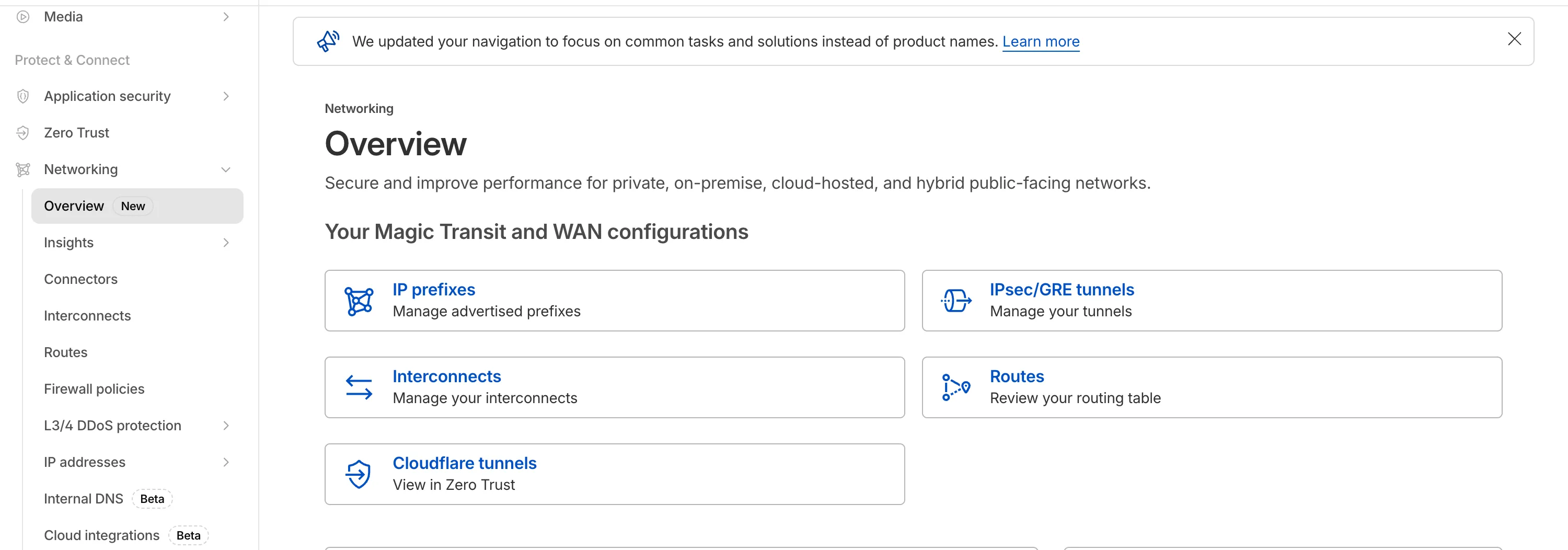
## 2025-12-31
**Breakout traffic visibility via NetFlow**
Magic WAN Connector now exports NetFlow data for breakout traffic to Magic Network Monitoring (MNM), providing visibility into traffic that bypasses Cloudflare's security filtering.
This feature allows you to:
* Monitor breakout traffic statistics in the Cloudflare dashboard.
* View traffic patterns for applications configured to bypass Cloudflare.
* Maintain visibility across all traffic passing through your Magic WAN Connector.
For more information, refer to [NetFlow statistics](https://developers.cloudflare.com/cloudflare-wan/analytics/netflow-analytics/).
## 2025-11-06
**Automatic Return Routing (Beta)**
Magic WAN now supports Automatic Return Routing (ARR), allowing customers to configure Magic on-ramps (IPsec/GRE/CNI) to learn the return path for traffic flows without requiring static routes.
Key benefits:
* **Route-less mode**: Static or dynamic routes are optional when using ARR.
* **Overlapping IP space support**: Traffic originating from customer sites can use overlapping private IP ranges.
* **Symmetric routing**: Return traffic is guaranteed to use the same connection as the original on-ramp.
This feature is currently in beta and requires the new Unified Routing mode (beta).
For configuration details, refer to [Configure Automatic Return Routing](https://developers.cloudflare.com/cloudflare-wan/configuration/manually/how-to/configure-routes/#configure-automatic-return-routing-beta).
## 2025-11-06
**Designate WAN link for breakout traffic**
Magic WAN Connector now allows you to designate a specific WAN port for breakout traffic, giving you deterministic control over the egress path for latency-sensitive applications.
With this feature, you can:
* Pin breakout traffic for specific applications to a preferred WAN port.
* Ensure critical traffic (such as Zoom or Teams) always uses your fastest or most reliable connection.
* Benefit from automatic failover to standard WAN port priority if the preferred port goes down.
This is useful for organizations with multiple ISP uplinks who need predictable egress behavior for performance-sensitive traffic.
For configuration details, refer to [Designate WAN ports for breakout apps](https://developers.cloudflare.com/cloudflare-wan/configuration/appliance/network-options/application-based-policies/breakout-traffic/#designate-wan-ports-for-breakout-apps).
## 2025-09-11
**DNS filtering for private network onramps**
[Magic WAN](https://developers.cloudflare.com/cloudflare-wan/zero-trust/cloudflare-gateway/#dns-filtering) and [WARP Connector](https://developers.cloudflare.com/cloudflare-one/networks/connectors/cloudflare-tunnel/private-net/warp-connector/site-to-internet/#configure-dns-resolver-on-devices) users can now securely route their DNS traffic to the Gateway resolver without exposing traffic to the public Internet.
Routing DNS traffic to the Gateway resolver allows DNS resolution and filtering for traffic coming from private networks while preserving source internal IP visibility. This ensures Magic WAN users have full integration with our Cloudflare One features, including [Internal DNS](https://developers.cloudflare.com/cloudflare-one/traffic-policies/resolver-policies/#internal-dns) and [hostname-based policies](https://developers.cloudflare.com/cloudflare-one/traffic-policies/egress-policies/#selector-prerequisites).
To configure DNS filtering, change your Magic WAN or WARP Connector DNS settings to use Cloudflare's shared resolver IPs, `172.64.36.1` and `172.64.36.2`. Once you configure DNS resolution and filtering, you can use _Source Internal IP_ as a traffic selector in your [resolver policies](https://developers.cloudflare.com/cloudflare-one/traffic-policies/resolver-policies/) for routing private DNS traffic to your [Internal DNS](https://developers.cloudflare.com/dns/internal-dns/).
## 2025-09-08
**Custom IKE ID for IPsec Tunnels**
Now, Magic WAN customers can configure a custom IKE ID for their IPsec tunnels. Customers that are using Magic WAN and a VeloCloud SD-WAN device together can utilize this new feature to create a high availability configuration.
This feature is available via API only. Customers can read the Magic WAN documentation to learn more about the [Custom IKE ID feature and the API call to configure it](https://developers.cloudflare.com/cloudflare-wan/configuration/common-settings/custom-ike-id-ipsec/).
## 2025-09-05
**Bidirectional tunnel health checks are compatible with all Magic on-ramps**
All bidirectional tunnel health check return packets are accepted by any Magic on-ramp.
Previously, when a Magic tunnel had a bidirectional health check configured, the bidirectional health check would pass when the return packets came back to Cloudflare over the same tunnel that was traversed by the forward packets.
There are SD-WAN devices, like VeloCloud, that do not offer controls to steer traffic over one tunnel versus another in a high availability tunnel configuration.
Now, when a Magic tunnel has a bidirectional health check configured, the bidirectional health check will pass when the return packet traverses over any tunnel in a high availability configuration.
## 2025-07-31
**Terraform V5 support for tunnels and routes**
The Cloudflare Terraform provider resources for Cloudflare WAN tunnels and routes now support Terraform provider version 5\. Customers using infrastructure-as-code workflows can manage their tunnel and route configuration with the latest provider version.
For more information, refer to the [Cloudflare Terraform provider documentation ↗](https://registry.terraform.io/providers/cloudflare/cloudflare/latest/docs).
## 2025-07-30
**Magic Transit and Magic WAN health check data is fully compatible with the CMB EU setting.**
Today, we are excited to announce that all Magic Transit and Magic WAN customers with CMB EU ([Customer Metadata Boundary - Europe](https://developers.cloudflare.com/data-localization/metadata-boundary/)) enabled in their account will be able to access GRE, IPsec, and CNI health check and traffic volume data in the Cloudflare dashboard and via API.
This ensures that all Magic Transit and Magic WAN customers with CMB EU enabled will be able to access all Magic Transit and Magic WAN features.
Specifically, these two GraphQL endpoints are now compatible with CMB EU:
* `magicTransitTunnelHealthChecksAdaptiveGroups`
* `magicTransitTunnelTrafficAdaptiveGroups`
## 2025-07-21
**Virtual Cloudflare One Appliance with KVM support (open beta)**
The KVM-based virtual Cloudflare One Appliance is now in open beta with official support for Proxmox VE.
Customers can deploy the virtual appliance on KVM hypervisors to connect branch or data center networks to Cloudflare WAN without dedicated hardware.
For setup instructions, refer to [Configure a virtual Cloudflare One Appliance](https://developers.cloudflare.com/cloudflare-wan/configuration/appliance/configure-virtual-appliance/).
## 2025-04-30
**Cloudflare One Appliance supports multiple DNS server IPs**
Cloudflare One Appliance DHCP server settings now support specifying multiple DNS server IP addresses in the DHCP pool.
Previously, customers could only configure a single DNS server per DHCP pool. With this update, you can specify multiple DNS servers to provide redundancy for clients at branch locations.
For configuration details, refer to [DHCP server](https://developers.cloudflare.com/cloudflare-wan/configuration/appliance/network-options/dhcp/dhcp-server/).
## 2025-02-14
**Configure your Magic WAN Connector to connect via static IP assigment**
You can now locally configure your [Magic WAN Connector](https://developers.cloudflare.com/cloudflare-wan/configuration/appliance/) to work in a static IP configuration.
This local method does not require having access to a DHCP Internet connection. However, it does require being comfortable with using tools to access the serial port on Magic WAN Connector as well as using a serial terminal client to access the Connector's environment.
For more details, refer to [WAN with a static IP address](https://developers.cloudflare.com/cloudflare-wan/configuration/appliance/configure-hardware-appliance/#bootstrap-via-serial-console).
## 2024-12-17
**Establish BGP peering over Direct CNI circuits**
Magic WAN and Magic Transit customers can use the Cloudflare dashboard to configure and manage BGP peering between their networks and their Magic routing table when using a Direct CNI on-ramp.
Using BGP peering allows customers to:
* Automate the process of adding or removing networks and subnets.
* Take advantage of failure detection and session recovery features.
With this functionality, customers can:
* Establish an eBGP session between their devices and the Magic WAN / Magic Transit service when connected via CNI.
* Secure the session by MD5 authentication to prevent misconfigurations.
* Exchange routes dynamically between their devices and their Magic routing table.
Refer to [Magic WAN BGP peering](https://developers.cloudflare.com/cloudflare-wan/configuration/manually/how-to/configure-routes/#configure-bgp-routes) or [Magic Transit BGP peering](https://developers.cloudflare.com/magic-transit/how-to/configure-routes/#configure-bgp-routes) to learn more about this feature and how to set it up.
## 2025-02-14
**Sites feature available to all Magic WAN customers**
All Magic WAN customers now have full access to the Magic WAN sites feature. Customers can configure a Magic WAN site either with or without a Magic WAN connector.
## 2024-12-17
**Magic WAN Connector configurable health checks**
Health check rate on Magic WAN Connector IPsec tunnels are now configurable.
## 2024-12-17
**BGP support for Cloudflare Network Interconnect (CNI)**
Magic WAN customers can now establish BGP peering over Direct CNI circuits. Customers can now dynamically exchange routes and path availability status between their router device and the Magic WAN table.
## 2024-12-12
**LAN Policy improvements for the Magic WAN Connector**
Magic WAN Connector LAN Policy now supports unidirectional traffic flows and port-ranges.
## 2024-10-01
**Early access testing for BGP on CNI 2.0 circuits**
Customers can exchange routes dynamically with their Magic virtual network overlay via Direct CNI or Cloud CNI based connectivity.
## 2024-09-27
**Magic WAN Connector sends Cloudflare One Client traffic to Internet**
All Magic WAN Connectors now route Cloudflare One Client traffic directly to the Internet, bypassing IPsec tunneling, to prevent double encapsulation of Cloudflare One Client traffic.
## 2024-07-17
**Updates to High Availability on the Magic WAN Connector**
The High Availability feature on Magic WAN Connector now supports additional failover conditions, DHCP lease syncing, and staggered upgrades.
## 2024-06-23
**ICMP support for traffic sourced from private IPs**
Magic WAN will now support ICMP traffic sourced from private IPs going to the Internet via Gateway.
## 2024-06-05
**Application based prioritization**
The Magic WAN Connector can now prioritize traffic on a per-application basis.
## 2024-05-31
**virtual IP addresses**
Customers using Gateway to filter traffic to Magic WAN destinations will now see traffic from Cloudflare egressing with the Cloudflare One Client virtual IP addresses (CGNAT range), rather than public Cloudflare IP addresses. This simplifies configuration and improves visibility for customers.
## 2024-01-23
**Network segmentation**
You can define policies in your Connector to either allow traffic to flow between your LANs without it leaving your local premises or to forward it via the Cloudflare network where you can add additional security features.
```json
{"@context":"https://schema.org","@type":"BreadcrumbList","itemListElement":[{"@type":"ListItem","position":1,"item":{"@id":"/directory/","name":"Directory"}},{"@type":"ListItem","position":2,"item":{"@id":"/cloudflare-wan/","name":"Cloudflare WAN"}},{"@type":"ListItem","position":3,"item":{"@id":"/cloudflare-wan/changelog/","name":"Changelog"}}]}
```
---
---
title: Glossary
description: Review the definitions for terms used across Cloudflare WAN (formerly Magic WAN) documentation.
image: https://developers.cloudflare.com/zt-preview.png
---
[Skip to content](#%5Ftop)
Was this helpful?
YesNo
[ Edit page ](https://github.com/cloudflare/cloudflare-docs/edit/production/src/content/docs/cloudflare-wan/glossary.mdx) [ Report issue ](https://github.com/cloudflare/cloudflare-docs/issues/new/choose)
Copy page
# Glossary
Review the definitions for terms used across Cloudflare WAN (formerly Magic WAN) documentation.
| Term | Definition |
| ----------------------------- | ----------------------------------------------------------------------------------------------------------------------------------------------------------------------------------------------------------------------------------------------------------------------------------------------- |
| anycast | Anycast is a network addressing and routing method in which incoming requests can be routed to a variety of different locations. Anycast typically routes incoming traffic to the nearest data center with the capacity to process the request efficiently. |
| data packet | A data packet is a unit of data consisting of user and control information. Information in a network is broken down into packets, that might follow different paths to their final destination. |
| equal-cost multi-path routing | A technique that uses hashes calculated from packet data to determine the route chosen. |
| GRE tunnel | Stands for generic routing encapsulation. It is a protocol wrapping one data packet within another type of data packet. This is useful for enabling protocols that are not normally supported by a network. |
| ICMP | Internet Control Message Protocol (ICMP) is used by network devices to send error messages and other operational information. ICMP is useful for diagnostic purposes, for example. |
| Internet key exchange (IKE) | The protocol Cloudflare uses to create the IPsec tunnel between Cloudflare WAN and the customer's device. |
| IPsec tunnel | Stands for Internet Protocol secure. It is a group of protocols for securing connections between devices, by encrypting IP packets. |
| maximum segment size (MSS) | MSS limits the size of packets, or small chunks of data, that travel across a network, such as the Internet. |
| on-ramp | Refers to a way of connecting a business network to Cloudflare. Examples of on-ramps, or ways to connect to Cloudflare, are Anycast GRE tunnels, Anycast IPsec tunnels, Cloudflare Network Interconnect (CNI), Cloudflare Tunnel, and WARP. |
| static route | A fixed configuration to route traffic through Anycast tunnels from Cloudflare global network to the customer's locations. |
| subnet | Also known as subnetwork. It refers to a network that is part of another network. |
| traffic steering | Cloudflare evaluates your route's health and steers traffic according to priorities defined by you and / or tunnel health. |
| tunnel health-check | A probe sent by Cloudflare to check for tunnel health. If a tunnel is not considered healthy, Cloudflare reroutes traffic to one that is considered healthy. |
| WAN | Stands for Wide Area Network. It refers to a computer network that connects groups of computers over large distances. WANs are often used by businesses to connect their office networks. The objective is to make each of the local area networks (LANs) be remotely connected and accessible. |
```json
{"@context":"https://schema.org","@type":"BreadcrumbList","itemListElement":[{"@type":"ListItem","position":1,"item":{"@id":"/directory/","name":"Directory"}},{"@type":"ListItem","position":2,"item":{"@id":"/cloudflare-wan/","name":"Cloudflare WAN"}},{"@type":"ListItem","position":3,"item":{"@id":"/cloudflare-wan/glossary/","name":"Glossary"}}]}
```
---
---
title: Configure with Appliance
description: Cloudflare One Appliance is a lightweight appliance you can install in corporate network locations to automatically connect, steer, and shape any IP traffic through secure IPsec tunnels. Cloudflare One Appliance is the easiest way to onboard your network locations to Cloudflare One. It is managed remotely through the Cloudflare dashboard, so you do not require an onsite IT team.
image: https://developers.cloudflare.com/zt-preview.png
---
[Skip to content](#%5Ftop)
Was this helpful?
YesNo
[ Edit page ](https://github.com/cloudflare/cloudflare-docs/edit/production/src/content/docs/cloudflare-wan/configuration/appliance/index.mdx) [ Report issue ](https://github.com/cloudflare/cloudflare-docs/issues/new/choose)
Copy page
# Configure with Appliance
Cloudflare One Appliance is a lightweight appliance you can install in corporate network locations to automatically connect, steer, and shape any IP traffic through [secure IPsec tunnels](https://developers.cloudflare.com/cloudflare-wan/configuration/appliance/reference/#security-and-other-information). Cloudflare One Appliance is the easiest way to onboard your network locations to Cloudflare One. It is managed remotely through the Cloudflare dashboard, so you do not require an onsite IT team.
You can [purchase Cloudflare One Appliance](https://developers.cloudflare.com/cloudflare-wan/configuration/appliance/configure-hardware-appliance/) software pre-installed on a Cloudflare-certified device, or download and deploy [Cloudflare One Virtual Appliance](https://developers.cloudflare.com/cloudflare-wan/configuration/appliance/configure-virtual-appliance/) in your own infrastructure.
Either option ensures the best possible connectivity to the closest Cloudflare network location, where Cloudflare will apply security controls and send traffic on an optimized route to its destination.
Cloudflare One Appliance has the same type of support process as other Cloudflare Enterprise products. Contact your team account manager to learn more.
Review this section to learn how to configure and deploy Cloudflare One Appliance.
* [ Configure hardware Appliance ](https://developers.cloudflare.com/cloudflare-wan/configuration/appliance/configure-hardware-appliance/)
* [ Configure Virtual Appliance ](https://developers.cloudflare.com/cloudflare-wan/configuration/appliance/configure-virtual-appliance/)
* [ Network options ](https://developers.cloudflare.com/cloudflare-wan/configuration/appliance/network-options/)
* [ Maintenance ](https://developers.cloudflare.com/cloudflare-wan/configuration/appliance/maintenance/)
* [ Device metrics ](https://developers.cloudflare.com/cloudflare-wan/configuration/appliance/device-metrics/)
* [ Reference ](https://developers.cloudflare.com/cloudflare-wan/configuration/appliance/reference/)
* [ Troubleshooting ](https://developers.cloudflare.com/cloudflare-wan/configuration/appliance/troubleshooting/)
```json
{"@context":"https://schema.org","@type":"BreadcrumbList","itemListElement":[{"@type":"ListItem","position":1,"item":{"@id":"/directory/","name":"Directory"}},{"@type":"ListItem","position":2,"item":{"@id":"/cloudflare-wan/","name":"Cloudflare WAN"}},{"@type":"ListItem","position":3,"item":{"@id":"/cloudflare-wan/configuration/","name":"Configuration"}},{"@type":"ListItem","position":4,"item":{"@id":"/cloudflare-wan/configuration/appliance/","name":"Configure with Appliance"}}]}
```
---
---
title: Configure hardware Appliance
description: In this page you will find instructions on how to configure Cloudflare One Appliance. This guide provides a step-by-step guide for Cloudflare One Appliance initial setup. You can either return here after setting up your Cloudflare One Appliance, or refer to the Maintenance section where you will find instructions on how to update your settings.
image: https://developers.cloudflare.com/zt-preview.png
---
[Skip to content](#%5Ftop)
Was this helpful?
YesNo
[ Edit page ](https://github.com/cloudflare/cloudflare-docs/edit/production/src/content/docs/cloudflare-wan/configuration/appliance/configure-hardware-appliance/index.mdx) [ Report issue ](https://github.com/cloudflare/cloudflare-docs/issues/new/choose)
Copy page
# Configure hardware Appliance
In this page you will find instructions on how to configure Cloudflare One Appliance. This guide provides a step-by-step guide for Cloudflare One Appliance initial setup. You can either return here after setting up your Cloudflare One Appliance, or refer to the [Maintenance](https://developers.cloudflare.com/cloudflare-wan/configuration/appliance/maintenance/) section where you will find instructions on how to update your settings.
## Prerequisites
You need to purchase [Cloudflare WAN](https://www.cloudflare.com/magic-wan/) before you can purchase and use Cloudflare One Appliance. Cloudflare One Appliance can function as your primary edge device for your network, or be deployed in-line with existing network gear.
You also need to purchase Cloudflare One Appliance before you can start configuring your settings in the Cloudflare dashboard. Contact your account representative to learn more about purchasing options for Cloudflare One Appliance.
---
## Before you begin
There are a couple of decisions you need to make when installing your Cloudflare One Appliance. Review the following topics for more information.
### Determine the need for a high availability configuration
You can install up to two instances of Cloudflare One Appliance for redundancy at each of your sites. If one of your devices fails, traffic will fail over to the other, ensuring that you never lose connectivity to that site.
In this type of high availability (HA) configuration, you will choose a reliable LAN interface as the HA link which will be used to monitor the health of the peer connector. HA links can be dedicated links or can be shared with other LAN traffic.
You must decide the type of configuration you want for your site from the beginning: no redundancy or with redundancy. You cannot add redundancy after finishing the configuration of your dashboard settings. If, at a later stage, you decide to enable redundancy, you will need to delete your Cloudflare One Appliance device in the Cloudflare dashboard, and start again.
Do you need a high availability configuration?
* If you need a high availability configuration for your premises, refer to[About high availability configurations](#about-high-availability-configurations) for details and learn how to configure your Cloudflare One Appliance device in this mode.
* If you do not need a high availability configuration for you premises, check if you need a [DHCP or a static IP setup](#decide-on-dhcp-vs-static-ip-connections) before proceeding to [Set up Cloudflare dashboard](#set-up-cloudflare-dashboard).
Warning
You cannot enable high availability for an existing Cloudflare One Appliance on-ramp. To add high availability to an existing Cloudflare One Appliance on-ramp in the Cloudflare dashboard, you need to delete the on-ramp and start again. Plan accordingly to create a high availability configuration from the start if needed.
### Decide on DHCP vs static IP connections
You can use Cloudflare One Appliance in both DHCP networks and networks that require a static IP configuration. At first boot, however, Cloudflare One Appliance needs to reach out to Cloudflare to download your settings and go through the activation process. If any of the networks plugged into your Cloudflare One Appliance device are DHCP enabled, do not use a VLAN, and have an Internet connection, that process is handled automatically. However, if all of the networks require more information to utilize, (such as a network with static IPs, or tagged VLAN networks) your Cloudflare One Appliance might need some more information to proceed.
There are couple of ways to provide this information. Choose the one that fits your workflow:
#### Option one - Activate on a DHCP Network
1. Connect Cloudflare One Appliance to a DHCP port with access to the Internet.
2. Follow the [setup flow](#set-up-cloudflare-dashboard) and activate your Cloudflare One Appliance device.
3. Refer to [WAN with a static IP address](#wan-with-a-static-ip-address).
#### Option two - Bootstrap via Serial Console
Refer to the [ Bootstrap workflow](#bootstrap-via-serial-console).
---
## Port speeds
The hardware version of the Cloudflare One Appliance includes two [SFP+ ports](https://en.wikipedia.org/wiki/Small%5FForm-factor%5FPluggable) that support 10G throughput, as well as six RJ45 ports that support 1G throughput.
Refer to [](/cloudflare-wan/configuration/appliance/configure-hardware-appliance/sfp-port-information)SFP+ port information for details on this topic.
---
## Set up Cloudflare dashboard
### Register your Appliance
To set up and use the hardware version of Cloudflare One Appliance (formerly Magic WAN Connector), you first need to register it with your account. This is not applicable to Virtual Cloudflare One Appliance.
1. Go to the **Connectors** page.
[ Go to **Connectors** ](https://dash.cloudflare.com/?to=/:account/magic-networks/connections)
2. In the **Appliances** tab > **Appliances**, select **Register an appliance**.
1. In **Appliance details** \> **Serial number**, insert the serial number for your device. You can optionally add notes about the Cloudflare One Appliance you are adding to the dashboard.
2. (Optional) Select **Add** under **Serial number** to add multiple Cloudflare One Appliances at once to your account.
3. Select **Register appliance**.
Your device is now registered with your account.
### Create a new profile
You need to create a profile for your appliance before connecting it to the Internet.
To create a profile:
1. Go to the **Connectors** page.
[ Go to **Connectors** ](https://dash.cloudflare.com/?to=/:account/magic-networks/connections)
2. Go to the **Appliances** tab > **Profiles** \> **Create a new profile**.
1. In **Name**, enter a descriptive name for your Cloudflare One Appliance. Optionally, you can also add a description for it.
2. You need to decide if you want to turn on high availability for the Cloudflare One Appliance. For details, refer to [About high availability configurations](#about-high-availability-configurations).
3. Select **Create and continue**.
4. Select **Add Appliance**. This will display a list of devices associated with your account. You need to have bought an Appliance already for it to appear here. Refer to [Prerequisites](#prerequisites) if no Appliance appears in this list.
5. If you have more than one Cloudflare One Appliance, choose the one that corresponds to the on-ramp you are creating. Cloudflare One Appliance devices are identified by a serial number, also known as a service tag. Use this information to choose the right Cloudflare One Appliance.
Select **Add Appliance** when you are ready to proceed.
6. Cloudflare One Appliance will be added to your account with an **Interrupt window** defined. The interrupt window is the time period when the Cloudflare One Appliance software can update, which may result in interruption to existing connections. You can change this later. Refer to [Interrupt window](https://developers.cloudflare.com/cloudflare-wan/configuration/appliance/maintenance/interrupt-service-window/) for more details on how to define when the Cloudflare One Appliance can update its systems.
7. Select **Continue** to proceed to creating your WAN and LAN networks.
### Create a WAN
* [ Dashboard ](#tab-panel-3961)
* [ API ](#tab-panel-3962)
When you have more than one anycast IP configured in your account (set up during your Cloudflare WAN (formerly Magic WAN) onboarding), Cloudflare One Appliance will automatically create at most two tunnels per WAN port. This improves reliability and performance, and requires no additional configuration on your part.
1. In **WAN configuration**, select **Create**. You can create one or more [wide area networks (WANs) ↗](https://www.cloudflare.com/learning/network-layer/what-is-a-wan/). Configuring multiple WANs will create multiple IPsec tunnels (one IPsec tunnel per WAN port). This allows Cloudflare One Appliance to load balance traffic over WANs of equal priority. It also allows Cloudflare One Appliance to failover between circuits according to their [health](https://developers.cloudflare.com/cloudflare-wan/reference/tunnel-health-checks/). Refer to [WAN settings](https://developers.cloudflare.com/cloudflare-wan/configuration/appliance/reference/#wan-settings) for more details.
Note
This is not the same as a high availability (HA) configuration. HA configurations need two Cloudflare One Appliance devices to work. For details, refer to [About high availability configurations](#about-high-availability-configurations).
2. In **Interface name**, enter a descriptive name for your WAN.
3. **Interface number** refers to the physical Cloudflare One Appliance Ethernet port that you are using for your WAN. The ports are labeled `GE1`, `GE2`, `GE3`, `GE4`, `GE5`, and `GE6`. Choose the number corresponding to the port that you are using in Appliance.
If you need a throughput higher than 1 Gbps, you can use one of the SFP+ ports. For details on hardware support, refer to [SFP+ port information](https://developers.cloudflare.com/cloudflare-wan/configuration/appliance/configure-hardware-appliance/sfp-port-information/).
4. In **VLAN ID**, enter a number between `0` and `4094` to specify a [VLAN ID](https://developers.cloudflare.com/cloudflare-wan/configuration/appliance/reference/#vlan-id).
5. In **Priority**, choose the priority for your WAN. Lower numbers have higher priority. For details on how Cloudflare calculates priorities, refer to [Traffic steering](https://developers.cloudflare.com/cloudflare-wan/reference/traffic-steering/).
6. In **Health check rate** configure the health check frequency for your site. Options are `low`, `mid`, and `high`. For details, refer to [Update tunnel health checks frequency](https://developers.cloudflare.com/cloudflare-wan/configuration/common-settings/update-tunnel-health-checks-frequency/).
7. **Addressing**: Select **DHCP**. This is needed the first time you set up your Cloudflare One Appliance to successfully download all settings to the machine and activate it. If you need a static IP address in your network environment:
1. Continue the set up flow to activate your Cloudflare One Appliance.
2. Refer to [WAN with a static IP address](#wan-with-a-static-ip-address). If you choose a static IP, you also need to specify the static IP and gateway addresses.
8. Select **Save** when you are finished.
Note
You will need your [account ID](https://developers.cloudflare.com/fundamentals/account/find-account-and-zone-ids/) and [API token](https://developers.cloudflare.com/fundamentals/api/get-started/account-owned-tokens/) to use the API.
Make a `POST` request [using the API](https://developers.cloudflare.com/api/resources/magic%5Ftransit/subresources/sites/subresources/wans/methods/create/) to create a WAN.
The `static_addressing` object is optional. Omit it if you are using DHCP. If you are using static addressing, add the `secondary_address` parameter when your site is in high availability (HA) mode.
Example:
Terminal window
```
curl https://api.cloudflare.com/client/v4/accounts/{account_id}/magic/sites/{site_id}/wans \
--header "X-Auth-Email: " \
--header "X-Auth-Key: " \
--header "Content-Type: application/json" \
--data '{
"name": "",
"physport": 1,
"priority": 0,
"vlan_tag": 0
}'
```
### Create a LAN
* [ Dashboard ](#tab-panel-3963)
* [ API ](#tab-panel-3964)
1. In **LAN configuration**, select **Create**.
2. Enter a descriptive name for your LAN in **Interface name**.
3. **Interface number** refers to the physical Cloudflare One Appliance Ethernet port that you are using for your LAN. The ports are labeled `GE1`, `GE2`, `GE3`, `GE4`, `GE5`, and `GE6`. Choose a number corresponding to the port that you are using in Appliance.
If you need a throughput higher than 1 Gbps, you can use one of the SFP+ ports. For details on hardware support, refer to [SFP+ port information](https://developers.cloudflare.com/cloudflare-wan/configuration/appliance/configure-hardware-appliance/sfp-port-information/).
4. In **VLAN ID**, specify a [VLAN ID](https://developers.cloudflare.com/cloudflare-wan/configuration/appliance/reference/#vlan-id) to create virtual LANs.
5. In **Static addressing** \> **Static address** give your Cloudflare One Appliance's LAN interface its IP address. You can also enable the following options if they suit your use case:
* **This is a DHCP server**: If your Cloudflare One Appliance is a [DHCP server](https://developers.cloudflare.com/cloudflare-wan/configuration/appliance/network-options/dhcp/dhcp-server/).
* **This is a DHCP relay**: If your Cloudflare One Appliance is a [DHCP relay](https://developers.cloudflare.com/cloudflare-wan/configuration/appliance/network-options/dhcp/dhcp-relay/).
6. (Optional) In **Directly attached subnet** \> **Static NAT prefix**, enter a CIDR prefix to enable NAT (network address translation). The prefix you enter here should be the same size as the prefix entered in **Static addressing**. For example, both networks have a subnet mask of `/24`: `192.168.100.0/24` and `10.10.100.0/24`.
7. (Optional) If your LAN contains additional subnets behind a layer 3 router, select **Add routed subnet** under **Routed subnets** to add them:
* **Prefix**: The CIDR prefix for the subnet behind the L3 router.
* **Next hop**: The address of the L3 router to which the Cloudflare One Appliance should forward packets for this subnet.
* **Static NAT prefix**: Optional setting. If you want to enable NAT for a routed subnet, supply an "external" prefix for the overlay-facing side of the NAT to use. It must be the same size as **Prefix**.
For details, refer to [Routed subnets](https://developers.cloudflare.com/cloudflare-wan/configuration/appliance/network-options/routed-subnets/).
8. Select **Save**.
9. Select **Done** to finish your configuration. Tunnels and static routes will be automatically created for your Cloudflare One Appliance, once it boots up.
Note
You will need your [account ID](https://developers.cloudflare.com/fundamentals/account/find-account-and-zone-ids/) and [API token](https://developers.cloudflare.com/fundamentals/api/get-started/account-owned-tokens/) to use the API.
Make a `POST` request [using the API](https://developers.cloudflare.com/api/resources/magic%5Ftransit/subresources/sites/subresources/lans/methods/create/) to create a LAN.
Example:
Terminal window
```
curl https://api.cloudflare.com/client/v4/accounts/{account_id}/magic/sites/{site_id}/lans \
--header "X-Auth-Email: " \
--header "X-Auth-Key: " \
--header "Content-Type: application/json" \
--data '{
"name": "",
"physport": 2,
"static_addressing": {
"address": "172.16.14.0/24"
},
"vlan_tag": 0
}'
```
#### Network segmentation
After setting up your LANs, you can configure your Cloudflare One Appliance to enable communication between them without traffic leaving your premises. For details, refer to [Network segmentation](https://developers.cloudflare.com/cloudflare-wan/configuration/appliance/network-options/network-segmentation/).
#### DHCP options
Cloudflare One Appliance supports different types of DHCP configurations. Cloudflare One Appliance can:
* Connect to a DHCP server or use a static IP address instead of connecting to a DHCP server.
* Act as a [DHCP server](https://developers.cloudflare.com/cloudflare-wan/configuration/appliance/network-options/dhcp/dhcp-server/).
* Use [DHCP relay](https://developers.cloudflare.com/cloudflare-wan/configuration/appliance/network-options/dhcp/dhcp-relay/) to connect to a DHCP server outside the location your Cloudflare One Appliance is in.
* [Reserve IP addresses](https://developers.cloudflare.com/cloudflare-wan/configuration/appliance/network-options/dhcp/dhcp-static-address-reservation/) for specific devices on your network.
### Add your Cloudflare One Appliance to a site
After finishing your Cloudflare One Appliance configuration, you need to add it to a site.
Sites represent the local network of a data center, office, or other physical location, and combine all on-ramps available there. Sites also allow you to check, at a glance, the state of your on-ramps and set up health alert settings so that Cloudflare notifies you when there are issues with the site's on-ramps.
Refer to [Set up a site](https://developers.cloudflare.com/cloudflare-wan/configuration/common-settings/sites/) for more information.
## Set up your Cloudflare One Appliance
### Device installation
There are several deployment options for Cloudflare One Appliance. Cloudflare One Appliance can act like a DHCP server for your local network, or integrate with your local setup and have static IP addresses assigned to it.
When Cloudflare One Appliance acts like the WAN router for your site, deployment will be something like this:
flowchart LR
accTitle: Appliance as WAN router
accDescr: Cloudflare One Appliance set up as a DHCP server, and connecting to the Internet.
a(Cloudflare One Appliance)--> b(Internet) --> c(Cloudflare)
subgraph Customer site
d[LAN 1] --> a
e[LAN 2] --> a
end
classDef orange fill:#f48120,color: black
class a,c orange
_Cloudflare One Appliance set up as a DHCP server, and connecting to the Internet._
In the following example, the Cloudflare One Appliance device sits behind the WAN router in your site, and on-ramps only some of the existing LANs to Cloudflare.
flowchart LR
accTitle: Appliance behind site router
accDescr: Cloudflare One Appliance connects to the router in the site, and only some of the LANs connect to Appliance.
a(Cloudflare One Appliance)--> b((Site's router)) --> c(Internet) --> i(Cloudflare)
subgraph Customer site
d[LAN 1] --> a
e[LAN 2] --> a
g(LAN 3) --> b
h(LAN 4) --> b
end
classDef orange fill:#f48120,color: black
class a,i orange
_Cloudflare One Appliance connects to the router in the site, and only some of the LANs connect to Appliance._
Refer to [Cloudflare One Appliance deployment options](https://developers.cloudflare.com/reference-architecture/diagrams/sase/cloudflare-one-appliance-deployment/) for a high-level explanation of the deployment options that make sense to most environments, as well as a few advanced use cases.
#### Firewall settings required
If there is a firewall deployed upstream of Cloudflare One Appliance, configure the firewall to allow the following traffic:
| Protocol/port | Destination IP/URL | Purpose |
| ------------------ | --------------------------------------- | ------------------------------------------------------------------------------------------------------------------------------- |
| UDP/53 | DNS destination IP 1.1.1.1 | Needed to allow DNS traffic to Cloudflare DNS servers. Cloudflare uses this port for DNS lookups of control plane API. |
| TCP/443 | \- | Cloudflare One Appliance will open outbound HTTPS connections over this port for control plane operations. |
| UDP/4500 | Destination IP 162.159.64.1 | Needed for Cloudflare One Appliance initialization and discovery through outbound connections. |
| UDP/4500 | Destination IP - Cloudflare anycast IPs | Needed for the Cloudflare anycast IPs assigned to your account for tunnel outbound connections. This traffic is tunnel traffic. |
| TCP/7844, UDP/7844 | Outbound connections | Used to support debugging features in Cloudflare One Appliance. |
| UDP/123 | http://time.cloudflare.com/ | Needed for Cloudflare One Appliance to periodically contact Cloudflare's Time Services. |
## Activate appliance
The Cloudflare One Appliance is shipped to you deactivated, and will only establish a connection to the Cloudflare network when it is activated. Cloudflare recommends leaving it deactivated until you finish [setting it up in the dashboard](#set-up-cloudflare-dashboard).
When Cloudflare One Appliance is first activated, you need to have Internet connection. If you chose to set up your Cloudflare One Appliance with DHCP you will need to have one of the Cloudflare One Appliance ports connected to the Internet through a device that supports DHCP. This is required so that the Cloudflare One Appliance can reach the Cloudflare global network and download the required configurations that you [set up](#set-up-cloudflare-dashboard).
If you set up your Cloudflare One Appliance with a static IP through the bootstrap method, you do not need a DHCP port. For details, refer to [ DHCP vs static IP connections](#decide-on-dhcp-vs-static-ip-connections).
Warning
Remember that if you chose the DHCP method you have to connect Cloudflare One Appliance through a route that supports DHCP for its first connection to the Internet. Otherwise, Cloudflare One Appliance will not work.
When you are ready to connect your Cloudflare One Appliance to the Cloudflare network:
1. Go to the **Connectors** page.
[ Go to **Connectors** ](https://dash.cloudflare.com/?to=/:account/magic-networks/connections)
1. Go to the **Appliances** tab > **Appliances**.
2. Find the Cloudflare One Appliance you want to activate, select the three dots next to it > **Edit**. Make sure you verify the serial number to choose the right Cloudflare One Appliance you want to activate.
3. In the new window, the **Status** dropdown will show as **Deactivated**. Select it to change the status to **Activated**.
4. The **Interrupt window** is the time period when the Cloudflare One Appliance software can update, which may result in interruption to existing connections. Choose a time period to minimize disruption to your sites. For details on defining when the Cloudflare One Appliance can update its systems, refer to [Interrupt window](https://developers.cloudflare.com/cloudflare-wan/configuration/appliance/maintenance/interrupt-service-window/).
5. Select **Update**.
---
## WAN with a static IP address
After activating your device, you can use it in a network configuration with the WAN interface set to a static IP address — that is, an Internet configuration that is not automatically set by DHCP. To use your Cloudflare One Appliance on a network configuration with a static IP, follow these steps:
Warning
Make sure you complete the setup workflow and activate your Cloudflare One Appliance before changing the WAN settings to a static IP.
1. Connect Cloudflare One Appliance to a DHCP port with access to the Internet.
2. [Create a new profile](#create-a-new-profile) in the dashboard.
3. Create a [DHCP WAN](#create-a-wan).
4. [Activate](#activate-appliance) and power on your Cloudflare One Appliance.
5. Wait 60 seconds.
6. Make changes to the [WAN settings](#create-a-wan) in the dashboard to a static IP set up.
7. Wait 60 seconds again.
8. Cloudflare One Appliance will go offline. This is normal and expected behavior.
9. Adjust your physical connections as required to match the static configuration.
10. Cloudflare One Appliance comes back online.
## Bootstrap via Serial Console
Advanced users can locally configure their Cloudflare One Appliance to work in a static IP configuration. This local method does not require having access to a DHCP Internet connection. However, it does require being comfortable with using tools to access the serial port on Cloudflare One Appliance as well as using a serial terminal client to access the environment in your Cloudflare One Appliance.
The following is a detailed description of how to use the serial port to configure your Cloudflare One Appliance locally.
Note
The `reset device` option in your Cloudflare One Appliance clears most of the configuration that is locally cached, resets the password to the default, and reboots.
### Equipment required
To access the serial port on Cloudflare One Appliance you will need the following equipment:
* The Cloudflare One Appliance device
* A Phillips-head screwdriver
* A micro-USB to USB-A cable (there should be one included in the packaging of your Cloudflare One Appliance device)
* A computer with an available USB port
* A serial terminal client
* Optional: if needed, a USB-A to USB-C converter dongle if your computer requires it
### 1\. Access the device's serial port
1. Using the Phillips screwdriver, loosen the screw covering the serial console panel on the back of the Cloudflare One Appliance and turn the panel out of the way.
* Pictures and more instructions can be found on [Dell's Technical Documents](https://www.dell.com/support/kbdoc/en-us/000134440/how-to-access-console-port-of-dell-emc-networking-virtual-edge-platform-1405-series).
2. Connect your computer to your Cloudflare One Appliance device using the USB cable.
#### Default password
The default password for your Cloudflare One Appliance device is the serial number (also known as a Service Tag for Dell devices), all uppercase followed by an `!` (for example, `A1B2C3D!`)
### 2\. Install a serial terminal client
To access the Cloudflare One Appliance device environment you need a serial terminal client. Follow these instructions to install one, based on your operating system.
#### Windows
Cloudflare recommends using PuTTY for Windows. Download PuTTY from the [official website](https://www.putty.org/) and then install it.
1. Check the COM port of the USB to UART device in the Windows Device Manager. It should appear as something similar to `Silicon Labs CP210x USB to UART Bridge (COMX)`.
2. Take note of the value in the parentheses (COMX).
* For details on creating a serial console connection, refer to the [Dell Documentation Page](https://infohub.delltechnologies.com/l/virtual-edge-platform-vep-1405-series-diag-os-and-tools-release-notes/bios-installation-and-configuration).
3. Launch PuTTY.
4. Under **Category**, make sure that **Session** (the first item) is selected.
5. Under **Connection type**, select **Serial**.
6. In the **Serial Line**, type in the COM port found in step 2 (for example, `COM1`).
7. In the **Speed**, enter `115200`.
8. Select Open on the bottom of the dialog box. A terminal window should pop up.
9. The screen may need to be manually refreshed when a new device is connected. You can do that by pressing `CTRL + C`.
#### macOS
Cloudflare recommends installing Screen for macOS. You can install Screen via `brew install screen`. If you do not have `brew` installed, follow the instructions on [Brew's Official Website](https://brew.sh/) to install it.
1. Open the macOS Terminal.
2. Run `ls /dev/cu.*` to list the connected serial devices.
3. The command should return an output similar to `/dev/cu.usbserial-0001`. Copy this output to the clipboard or note this down somewhere else.
4. Run `sudo screen -adRUS mconn 115200`.
5. The screen may need to be manually refreshed when a new device is connected. You can do that by pressing `CMD + C`.
#### Linux
Cloudflare recommends installing Screen for Linux. You can install Screen via your package manager of choice. For example, for Debian/Ubuntu, install by running `sudo apt update && sudo apt install screen`
1. Open Terminal.
2. List the connected serial devices by running `ls /dev/serial/by-id/*`.
3. The command should return an output similar to `/dev/serial/by-id/usb-Silicon_Labs_CP2102_USB_to_UART_Bridge_Controller_0001-if00-port0`. Copy this to the clipboard or note this down.
4. Run `sudo screen -adRUS mconn 115200`.
5. The screen may need to be manually refreshed when a new device is connected. You can do that by pressing `CTRL + C`.
### 3\. Configure a static IP
The `reset device` option in your Cloudflare One Appliance clears most of the configuration that is locally cached, resets the password to the default, and reboots.
1. Log into your Cloudflare One Appliance device. You will be prompted to change your password if you attempt to log in with the default password.
2. From the menu, go to **Bootstrap** with the arrow keys and select it with the Enter key.
3. Select the jack (physical port) you want to configure for the initialization of the appliance.
4. Enter the VLAN tag (if applicable) of the network. Leave it blank if untagged.
5. Select the `static` option as your network type.
Note
The main reason to use the bootstrapper is if every network your Cloudflare One Appliance device is plugged into is either static, behind a VLAN, or both. If you find yourself here and configuring a network with DHCP and no VLAN, you are probably not in the right place. See the section on configuring your Cloudflare One Appliance [via the dashboard](#set-up-cloudflare-dashboard).
1. Enter the IP address you would like the appliance to have in CIDR form (for example, `10.0.0.2/24`).
2. Enter the IP address of the Internet gateway (this must be in the same subnet as the previous IP address you entered and must not be the same address).
3. Select **Save** and confirm that you want to use the new settings.
4. The Cloudflare One Appliance will download the rest of the settings from Cloudflare. The last heartbeat of the Cloudflare One Appliance should update once it has made contact with Cloudflare.
---
## About high availability configurations
You need to deploy two Appliances in your premises before you can set up a site in high availability. When you set up a site in high availability, the WANs and LANs in your Cloudflare One Appliance have the same configuration but are replicated on two nodes. In case of failure of one of the devices, the other device becomes the active node, taking over the configuration of the LAN gateway IP and allowing traffic to continue without disruption.
Because Cloudflare One Appliances in high availability configurations share a single site, you need to set up:
* **Static address**: The IP for the primary node in your site.
* **Secondary static address**: The IP for the secondary node in your site.
* **Virtual static address**: The IP that the LAN south of the Cloudflare One Appliance device will forward traffic to, which is the LAN's gateway IP.
Make sure all IPs are part of the same subnet.
For detailed information about the expected behavior of high availability configurations, refer to the [High availability configurations](https://developers.cloudflare.com/cloudflare-wan/configuration/appliance/reference/#high-availability-configurations) reference page.
### Create a high availability configuration
You cannot enable high availability for an existing site. To add high availability to an existing site in the Cloudflare dashboard, you need to delete the site and start again.
To set up a high availability configuration:
1. Follow the steps in [Create a new profile](#create-a-new-profile) up until step 4.
1. After naming your site, select **Turn on high availability**.
2. Select **Create and continue**.
3. Select **Add Appliance**.
4. From the list, choose your first Cloudflare One Appliance > **Add Appliance**.
5. Back on the previous screen, select **Add secondary appliance**.
6. From the list, choose your second Cloudflare One Appliance > **Add Appliance**.
7. Select **Continue** to create a WAN. If you are configuring a static IP, configure the IP for the primary node as the static address, and the IP for the secondary node as the secondary static address.
8. To create a LAN, follow the steps in [Create a LAN](#create-a-lan) up until step 4.
9. In **Static address**, enter the IP for the primary node in your site. For example, `192.168.10.1/24`.
10. In **Secondary static address**, enter the IP for the secondary node in your site. For example, `192.168.10.2/24`.
11. In **Virtual static address**, enter the IP that the LAN south of the Cloudflare One Appliance device will forward traffic to. For example, `192.168.10.3/24`.
12. Select **Save**.
13. From the **High availability probing link** drop-down menu, select the port that should be used to monitor the node's health. Cloudflare recommends you choose a reliable interface as the HA probing link. The primary and secondary node's probing link should be connected over a switch, and cannot be a direct connection.
14. Follow the instructions in [Set up your Cloudflare One Appliance](#set-up-your-cloudflare-one-appliance) and [Activate appliance](#activate-appliance) to finish setting up your Appliances.
---
## IPsec tunnels and static routes
Cloudflare One Appliance automatically creates [IPsec tunnels](https://developers.cloudflare.com/cloudflare-wan/reference/gre-ipsec-tunnels/#ipsec-tunnels) and [static routes](https://developers.cloudflare.com/cloudflare-wan/reference/traffic-steering/) for you. You cannot configure these manually.
To check the IPsec tunnels and static routes created by your Cloudflare One Appliance:
1. Go to the **Connectors** page.
[ Go to **Connectors** ](https://dash.cloudflare.com/?to=/:account/magic-networks/connections)
1. The **IPsec/GRE tunnels** tab shows a list of all the IPsec tunnels created by your Cloudflare One Appliance.
2. Go to the **Routes** page.
[ Go to **Routes** ](https://dash.cloudflare.com/?to=/:account/magic-networks/routes)
1. Here you can inspect the static routes created by your Cloudflare One Appliance.
---
## Next steps
* [Network options](https://developers.cloudflare.com/cloudflare-wan/configuration/appliance/network-options/)
* [Maintenance](https://developers.cloudflare.com/cloudflare-wan/configuration/appliance/maintenance/)
* [Reference information](https://developers.cloudflare.com/cloudflare-wan/configuration/appliance/reference/)
* [Troubleshooting](https://developers.cloudflare.com/cloudflare-wan/configuration/appliance/troubleshooting/)
```json
{"@context":"https://schema.org","@type":"BreadcrumbList","itemListElement":[{"@type":"ListItem","position":1,"item":{"@id":"/directory/","name":"Directory"}},{"@type":"ListItem","position":2,"item":{"@id":"/cloudflare-wan/","name":"Cloudflare WAN"}},{"@type":"ListItem","position":3,"item":{"@id":"/cloudflare-wan/configuration/","name":"Configuration"}},{"@type":"ListItem","position":4,"item":{"@id":"/cloudflare-wan/configuration/appliance/","name":"Configure with Appliance"}},{"@type":"ListItem","position":5,"item":{"@id":"/cloudflare-wan/configuration/appliance/configure-hardware-appliance/","name":"Configure hardware Appliance"}}]}
```
---
---
title: SFP+ port information
description: The hardware version of Cloudflare One Appliance (formerly Magic WAN Connector) includes two SFP+ ports that support 10G throughput. These ports can be configured as either a WAN or a LAN port, like all of the 1G RJ45 ports in the machine. Because a 10G WAN uplink will often be bottlenecked by IPsec tunnel speeds, the SFP+ ports are most useful for configuring high speed LANs, and for using fiber connections.
image: https://developers.cloudflare.com/zt-preview.png
---
[Skip to content](#%5Ftop)
Was this helpful?
YesNo
[ Edit page ](https://github.com/cloudflare/cloudflare-docs/edit/production/src/content/docs/cloudflare-wan/configuration/appliance/configure-hardware-appliance/sfp-port-information.mdx) [ Report issue ](https://github.com/cloudflare/cloudflare-docs/issues/new/choose)
Copy page
# SFP+ port information
The hardware version of Cloudflare One Appliance (formerly Magic WAN Connector) includes two [SFP+ ports ↗](https://en.wikipedia.org/wiki/Small%5FForm-factor%5FPluggable) that support 10G throughput. These ports can be configured as either a WAN or a LAN port, like all of the 1G RJ45 ports in the machine. Because a 10G WAN uplink will often be bottlenecked by IPsec tunnel speeds, the SFP+ ports are most useful for configuring high speed LANs, and for using fiber connections.
Virtual Appliance and SFP+ ports
Since you decide and set up the hardware where Virtual Appliance runs, you can ignore the information on this page.
## Port configuration
SFP+ ports are next to the regular LAN ports. They are represented as follows in the dashboard:
* SFP+ **port 1** is represented by **port 7** in the dashboard
* SFP+ **port 2** is represented by **port 8** in the dashboard
_The left port, SFP+ 1, is port 7\. The right port, SFP+ 2, is port 8._
## SFP+ module compatibility
Cloudflare One Appliance only supports 10Gbps SFP+ modules, including RJ45, DAC, and fiber, among others. Many 1 Gbps modules are incompatible with the Intel driver used internally, and thus are not supported.
Cloudflare supports the following SFP+ inputs:
* 10 Gbps Intel-compatible optics using 10GBase-SR, LR, ER. This includes Intel-compatible active optical cables (AOC) cables at 10 Gbps.
* 10 Gbps DAC Twinax cables, compatible with SFF-8431 v4.1 and SFF-8472 v10.4
* 10GBASE-T RJ45 converter modules
Cloudflare successfully deployed commonly available 10G modules that are also compatible across many vendors:
* StarTech Dell EMC Twinax SFP+ DAC
* Ubiquiti multi-mode, duplex, 10 Gbps fiber transceiver modules
Keep in mind that SFP+ modules/cables have to be compatible at both ends, that is, both sides of the connection should be 10 Gbps, and it should really be the same module/cable that is compatible with both hardware stacks. The choice of module/optic/cable ultimately depends on your specific interoperability needs, and it is much less of a "plug and play" situation as one expects from RJ45.
## Recover from unsupported SFP+ inputs
SFP+ modules should be installed and tested prior to deploying Cloudflare One Appliance into production usage.
An unsupported SFP+ input is indicated by the interface failing to come up (that is, the Cloudflare One Appliance has no status lights), and also by the port (7 or 8) going offline until the hardware is rebooted.
When an unsupported module is plugged, the module should be removed and then the Cloudflare One Appliance rebooted by removing power for five seconds. The module should not remain plugged during reboot, or the Cloudflare One Appliance will have to be rebooted again after the module is removed.
```json
{"@context":"https://schema.org","@type":"BreadcrumbList","itemListElement":[{"@type":"ListItem","position":1,"item":{"@id":"/directory/","name":"Directory"}},{"@type":"ListItem","position":2,"item":{"@id":"/cloudflare-wan/","name":"Cloudflare WAN"}},{"@type":"ListItem","position":3,"item":{"@id":"/cloudflare-wan/configuration/","name":"Configuration"}},{"@type":"ListItem","position":4,"item":{"@id":"/cloudflare-wan/configuration/appliance/","name":"Configure with Appliance"}},{"@type":"ListItem","position":5,"item":{"@id":"/cloudflare-wan/configuration/appliance/configure-hardware-appliance/","name":"Configure hardware Appliance"}},{"@type":"ListItem","position":6,"item":{"@id":"/cloudflare-wan/configuration/appliance/configure-hardware-appliance/sfp-port-information/","name":"SFP+ port information"}}]}
```
---
---
title: Configure Virtual Appliance
description: Learn how to configure Cloudflare One Virtual Appliance on VMWare ESXi or Proxmox Virtual Environment
image: https://developers.cloudflare.com/zt-preview.png
---
[Skip to content](#%5Ftop)
Was this helpful?
YesNo
[ Edit page ](https://github.com/cloudflare/cloudflare-docs/edit/production/src/content/docs/cloudflare-wan/configuration/appliance/configure-virtual-appliance.mdx) [ Report issue ](https://github.com/cloudflare/cloudflare-docs/issues/new/choose)
Copy page
# Configure Virtual Appliance
Cloudflare One Virtual Appliance is a virtual device alternative to the hardware based Cloudflare One Appliance. These two versions of Cloudflare One Appliance are identical otherwise.
Currently, you can set up Cloudflare One Virtual Appliance on VMWare ESXi and Proxmox Virtual Environment. Support for Proxmox is in beta.
In this page you will find instructions on how to configure Cloudflare One Appliance. This guide provides a step-by-step guide for Cloudflare One Appliance initial setup. You can either return here after setting up your Cloudflare One Appliance, or refer to the [Maintenance](https://developers.cloudflare.com/cloudflare-wan/configuration/appliance/maintenance/) section where you will find instructions on how to update your settings.
## Prerequisites
Before you can install Cloudflare One Virtual Appliance, you need an Enterprise account with Cloudflare WAN. Additionally, you need to have a VMware or Proxmox host with sufficient compute, memory, and storage to run the virtual machine with Cloudflare One Virtual Appliance. This includes:
* Intel x86 CPU architecture
* ESXi hypervisor 7.0U1 or higher
* 4 virtual CPUs per virtual appliance (We recommend deployment with a 1:1 virtual CPU to physical core allocation to avoid CPU over contention which will cause packet loss.)
* 8 GB of RAM per virtual appliance
* 8 GB of disk per virtual appliance
* One vSwitch port group or VLAN with access to the Internet (for example, through a WAN)
* One or more vSwitch port group or VLAN that will be the internal LAN
For details on installing ESXi and configuring a virtual machine, refer to [VMware's documentation](https://docs.vmware.com/en/VMware-vSphere/7.0/com.vmware.esxi.install.doc/GUID-B2F01BF5-078A-4C7E-B505-5DFFED0B8C38.html).
For details on installing Virtual environment and configuring a virtual machine, refer to [Proxmox documentation](https://www.proxmox.com/en/products/proxmox-virtual-environment/get-started).
---
## Before you begin
There are a couple of decisions you need to make when installing your Cloudflare One Virtual Appliance. Review the following topics for more information.
### Determine the need for a high availability configuration
You can install up to two instances of Cloudflare One Virtual Appliance for redundancy at each of your sites. If one of your devices fails, traffic will fail over to the other, ensuring that you never lose connectivity to that site.
In this type of high availability (HA) configuration, you will choose a reliable LAN interface as the HA link which will be used to monitor the health of the peer connector. HA links can be dedicated links or can be shared with other LAN traffic.
You must decide the type of configuration you want for your site from the beginning: no redundancy or with redundancy. You cannot add redundancy after finishing the configuration of your dashboard settings. If, at a later stage, you decide to enable redundancy, you will need to delete your Cloudflare One Virtual Appliance device in the Cloudflare dashboard, and start again.
Do you need a high availability configuration?
* If you need a high availability configuration for your premises, refer to[About high availability configurations](#about-high-availability-configurations) for details and learn how to configure your Cloudflare One Virtual Appliance device in this mode.
* If you do not need a high availability configuration for you premises, check if you need a [DHCP or a static IP setup](#decide-on-dhcp-vs-static-ip-connections) before proceeding to [Set up Cloudflare dashboard](#set-up-cloudflare-dashboard).
Warning
You cannot enable high availability for an existing Cloudflare One Virtual Appliance on-ramp. To add high availability to an existing Cloudflare One Virtual Appliance on-ramp in the Cloudflare dashboard, you need to delete the on-ramp and start again. Plan accordingly to create a high availability configuration from the start if needed.
### Decide on DHCP vs static IP connections
Cloudflare One Virtual Appliance uses a DHCP connection at first boot to download your settings and go through the activation process. However, if you need to use a static IP in your Cloudflare One Virtual Appliance, and this is a fresh install:
1. Connect the machine with your Cloudflare One Virtual Appliance VM to a DHCP port with access to the Internet.
2. Follow the [setup flow](#set-up-cloudflare-dashboard) and activate your Cloudflare One Virtual Appliance device.
3. Refer to [WAN with a static IP address](#wan-with-a-static-ip-address).
---
## Configure a virtual machine
Select the appropriate tab to configure Cloudflare One Virtual Appliance on VMWare ESXi or Proxmox Virtual Environment.
* [ VMWare ESXi ](#tab-panel-3969)
* [ Proxmox Virtual Environment (beta) ](#tab-panel-3970)
**1\. Obtain the VMWare image**
Contact your account team at Cloudflare to obtain the Cloudflare One Virtual Appliance OVA package and license keys. The OVA image includes the files required to install and configure the virtual machine (VM) for Cloudflare One Virtual Appliance with the appropriate settings. For details, refer to [VMWare VMs documentation](https://docs.vmware.com/en/VMware-vSphere/7.0/com.vmware.vsphere.vm%5Fadmin.doc/GUID-AE61948B-C2EE-436E-BAFB-3C7209088552.html).
This image can be deployed multiple times to create several instances of a Cloudflare One Virtual Appliance, in different locations or on the same ESXi host.
You will consume one license key for each instance created. For example, if you want to deploy 10 Cloudflare One Virtual Appliances you should request 10 license keys, and your account team will create 10 Cloudflare One Virtual Appliance instances in your Cloudflare dashboard.
**2\. Deploy the Cloudflare One Virtual Appliance on VMware**
The following instructions assume you already have VMware ESXi hypervisor installed with sufficient resources. For details, refer to [Prerequisites](#prerequisites).
1. When setting up your VMware ESXi, you need to create port groups for Cloudflare One Virtual Appliance. Go to **Networking** \> **Port groups**, and prepare your vSwitch port groups and/or VLANs for your desired network topology. For example, a simple deployment typically has:
* A WAN port group where the Cloudflare One Virtual Appliance will get an IP address (static or DHCP) that has access to the Internet.
* A LAN port group, where the Cloudflare One Virtual Appliance will act as default router, and possibly DHCP server.
* A null, or unused, port group for allocating unused virtual interfaces in the Cloudflare One Virtual Appliance. You can, for example, create a null port group with the name of `Null port group`, and a **VLAN ID** of `999`.
VLAN tagging
Cloudflare One Virtual Appliance supports creating subinterfaces through the use of [802.1Q VLAN tagging ↗](https://en.wikipedia.org/wiki/IEEE%5F802.1Q).
Use VLAN ID `0` when:
* Connected to a Port Group or Distributed Port Group that is associated with a specific VLAN.
* Connected to a Port Group or Distributed Port Group that is configured as a trunk that requires untagged packets.
You can also configure subinterfaces on the Cloudflare One Virtual Appliance by associating the network interface with a Port Group or Distributed Port Group trunk and specifying a VLAN ID in addition to the port associated with the network interface (VLAN ID `1`\-`4094`).
Refer to [VMware's documentation](https://kb.vmware.com/s/article/1003825) for more information.
1. Extract the files in the OVA image provided by your Cloudflare account team. For example:
Terminal window
```
tar -xvf mconn-2024-1-3.ova
```
Take note of the folder where you are extracting the files to, as you will need to refer to that folder when creating the VM.
1. Go to **Virtual Machines** \> **Create/Register VM** wizard to start deploying the Cloudflare One Virtual Appliance.
2. Select **Deploy a virtual machine from an OVF or OVA file** \> **Next**.
3. Choose a descriptive name for your virtual machine.
4. Upload the files you have extracted from the OVA image. These include `mconn.ovf`, `mconn.nvram`, and `mconn.vmdk`.
5. Select where you want to save the files extracted from the OVA image > **Next**.
6. In **Networking mappings**, select assignments for your desired topology according to the port groups you set up previously:
1. For example, map `eno1` port to `VM Network` to create your WAN, and `eno2` to `LAN0` to act as your LAN port.
2. Allocate any unused ports to the `null` port group.
3. Take note of your configuration. You will need this information to configure your network in the Cloudflare dashboard.
7. In **Disk provisioning**, select **Thin**.
8. Before completing the deployment wizard, disable **Power on automatically**. This is important so that you can configure the license key prior to boot.
9. Configure the virtual machine with the license key your account team provided you:
1. Select the Cloudflare One Virtual Appliance's VM > **Settings**.
2. Go to **VM Options** \> **Advanced** \> **Edit Configuration**.
3. Select **Add parameter** to add your license key. Scroll down to the last entry (this is where VMware adds the new parameter), and add the following two new entries:
* **Key**: `guestinfo.cloudflare.identity`
* **Value** ``
Note
You cannot use the same license key twice, or reuse a key once the virtual machine has been registered with Cloudflare. You need a new key from your account team for every new Cloudflare One Virtual Appliance.
1. Select **Save** to finish configuring your Cloudflare One Virtual Appliance.
2. Continue setup in your [Cloudflare dashboard.](#set-up-cloudflare-dashboard)
**1\. Obtain the Cloudflare One Virtual Appliance script**
Contact your account team at Cloudflare to obtain your license keys and the Cloudflare One Virtual Appliance script for Proxmox. The script will set up and configure a Proxmox virtual machine with the appropriate settings for Cloudflare One Virtual Appliance. For details on system requirements, refer to [Prerequisites](#prerequisites).
The script can be deployed multiple times to create several instances of a Cloudflare One Virtual Appliance, in different locations or on the same Proxmox host. You will consume one license key for each instance created. For example, if you want to deploy 10 Cloudflare One Virtual Appliances you should request 10 license keys, and your account team will create 10 Cloudflare One Virtual Appliance instances in your Cloudflare dashboard.
**2\. Deploy the Cloudflare One Virtual Appliance on Proxmox**
The following instructions assume you already have Proxmox Virtual Environment installed with sufficient resources. For details, refer to [Prerequisites](#prerequisites).
1. In the terminal prompt of your Proxmox server, load the script provided by your account team. For example: `bash YOUR_SCRIPT`. You need elevated privileges to run the script.
2. You will be prompted to create a new Cloudflare One Virtual Appliance. Select **yes** to proceed.
3. Set up your Virtual Appliance name.
4. Enter your license key.
Note
You cannot use the same license key twice, or reuse a key once the virtual machine has been registered with Cloudflare. You need a new key from your account team for every new Cloudflare One Virtual Appliance.
1. Select the network interface card (NIC) you want to use with Cloudflare One Virtual Appliance.
2. Select the network bridge that corresponds to the physical network interface card (NIC) on your host machine. This bridge allows the network adapter in the virtual machine to communicate through the NIC in the host, as if it were directly connected to the physical network.
3. (Optional) Configure your VLAN setting if needed.
VLAN tagging
Cloudflare One Virtual Appliance supports creating subinterfaces through the use of [802.1Q VLAN tagging ↗](https://en.wikipedia.org/wiki/IEEE%5F802.1Q).
Use VLAN ID `0` when:
* Connected to a Port Group or Distributed Port Group that is associated with a specific VLAN.
* Connected to a Port Group or Distributed Port Group that is configured as a trunk that requires untagged packets.
You can also configure subinterfaces on the Cloudflare One Virtual Appliance by associating the network interface with a Port Group or Distributed Port Group trunk and specifying a VLAN ID in addition to the port associated with the network interface (VLAN ID `1`\-`4094`).
Refer to [Proxmox documentation](https://www.proxmox.com/en/products/proxmox-virtual-environment/get-started) for more information.
1. Finish your configuration.
2. The script will apply your settings and configure the virtual machine template for Cloudflare One Virtual Appliance.
3. In the **Hardware settings** for the new VM, make sure the hardware settings match the minimum requirements for running Cloudflare One Virtual Appliance. Make changes to the RAM and CPU if needed.
4. Continue setup in your [Cloudflare dashboard](#set-up-cloudflare-dashboard).
---
## Set up Cloudflare dashboard
### Create a new profile
You need to create a profile for your appliance before connecting it to the Internet.
To create a profile:
1. Go to the **Connectors** page.
[ Go to **Connectors** ](https://dash.cloudflare.com/?to=/:account/magic-networks/connections)
2. Go to the **Appliances** tab > **Profiles** \> **Create a new profile**.
1. In **Name**, enter a descriptive name for your Cloudflare One Virtual Appliance. Optionally, you can also add a description for it.
2. You need to decide if you want to turn on high availability for the Cloudflare One Virtual Appliance. For details, refer to [About high availability configurations](#about-high-availability-configurations).
3. Select **Create and continue**.
4. Select **Add Appliance**. This will display a list of devices associated with your account. For a Virtual Appliance to appear you need to:
* **VMWare:** Have already obtained your OVA package and license keys if you are installing on VMWare.
* **Proxmox:** Have already obtained your Virtual Appliance Script and license keys if you are installing on Proxmox.
For details, refer to [Configure a virtual machine](#configure-a-virtual-machine) and select the appropriate tab.
5. If you have more than one Cloudflare One Virtual Appliance, choose the one that corresponds to the on-ramp you are creating. Cloudflare One Virtual Appliance devices are identified by a serial number, also known as a service tag. Use this information to choose the right Cloudflare One Virtual Appliance.
Select **Add Appliance** when you are ready to proceed.
6. Cloudflare One Virtual Appliance will be added to your account with an **Interrupt window** defined. The interrupt window is the time period when the Cloudflare One Virtual Appliance software can update, which may result in interruption to existing connections. You can change this later. Refer to [Interrupt window](https://developers.cloudflare.com/cloudflare-wan/configuration/appliance/maintenance/interrupt-service-window/) for more details on how to define when the Cloudflare One Virtual Appliance can update its systems.
7. Select **Continue** to proceed to creating your WAN and LAN networks.
### Create a WAN
* [ Dashboard ](#tab-panel-3965)
* [ API ](#tab-panel-3966)
When you have more than one anycast IP configured in your account (set up during your Cloudflare WAN (formerly Magic WAN) onboarding), Cloudflare One Virtual Appliance will automatically create at most two tunnels per WAN port. This improves reliability and performance, and requires no additional configuration on your part.
1. In **WAN configuration**, select **Create**. You can create one or more [wide area networks (WANs) ↗](https://www.cloudflare.com/learning/network-layer/what-is-a-wan/). Configuring multiple WANs will create multiple IPsec tunnels (one IPsec tunnel per WAN port). This allows Cloudflare One Virtual Appliance to load balance traffic over WANs of equal priority. It also allows Cloudflare One Virtual Appliance to failover between circuits according to their [health](https://developers.cloudflare.com/cloudflare-wan/reference/tunnel-health-checks/). Refer to [WAN settings](https://developers.cloudflare.com/cloudflare-wan/configuration/appliance/reference/#wan-settings) for more details.
Note
This is not the same as a high availability (HA) configuration. HA configurations need two Cloudflare One Virtual Appliance devices to work. For details, refer to [About high availability configurations](#about-high-availability-configurations).
2. In **Interface name**, enter a descriptive name for your WAN.
3. **Interface number** needs to correspond to the virtual network interface on the Virtual Appliance instance you have set up in VMware. Following our example from the previous steps, you need to choose port `1` since that is what corresponds to the `eno1` port we set up in VMware.
4. In **VLAN ID**, enter a number between `0` and `4094` to specify a [VLAN ID](https://developers.cloudflare.com/cloudflare-wan/configuration/appliance/reference/#vlan-id).
5. In **Priority**, choose the priority for your WAN. Lower numbers have higher priority. For details on how Cloudflare calculates priorities, refer to [Traffic steering](https://developers.cloudflare.com/cloudflare-wan/reference/traffic-steering/).
6. In **Health check rate** configure the health check frequency for your site. Options are `low`, `mid`, and `high`. For details, refer to [Update tunnel health checks frequency](https://developers.cloudflare.com/cloudflare-wan/configuration/common-settings/update-tunnel-health-checks-frequency/).
7. **Addressing**: Select **DHCP**. This is needed the first time you set up your Cloudflare One Virtual Appliance to successfully download all settings to the machine and activate it. If you need a static IP address in your network environment:
1. Continue the set up flow to activate your Cloudflare One Virtual Appliance.
2. Refer to [WAN with a static IP address](#wan-with-a-static-ip-address). If you choose a static IP, you also need to specify the static IP and gateway addresses.
8. Select **Save** when you are finished.
Note
You will need your [account ID](https://developers.cloudflare.com/fundamentals/account/find-account-and-zone-ids/) and [API token](https://developers.cloudflare.com/fundamentals/api/get-started/account-owned-tokens/) to use the API.
Make a `POST` request [using the API](https://developers.cloudflare.com/api/resources/magic%5Ftransit/subresources/sites/subresources/wans/methods/create/) to create a WAN.
The `static_addressing` object is optional. Omit it if you are using DHCP. If you are using static addressing, add the `secondary_address` parameter when your site is in high availability (HA) mode.
Example:
Terminal window
```
curl https://api.cloudflare.com/client/v4/accounts/{account_id}/magic/sites/{site_id}/wans \
--header "X-Auth-Email: " \
--header "X-Auth-Key: " \
--header "Content-Type: application/json" \
--data '{
"name": "",
"physport": 1,
"priority": 0,
"vlan_tag": 0
}'
```
### Create a LAN
* [ Dashboard ](#tab-panel-3967)
* [ API ](#tab-panel-3968)
1. In **LAN configuration**, select **Create**.
2. Enter a descriptive name for your LAN in **Interface name**.
3. **Interface number** needs to correspond to the virtual LAN interface on the Virtual Appliance instance you have set up in VMware. Following our example from the previous steps, you need to choose port `2` since that is what corresponds to the `eno2` port we set up in VMware.
4. In **VLAN ID**, specify a [VLAN ID](https://developers.cloudflare.com/cloudflare-wan/configuration/appliance/reference/#vlan-id) to create virtual LANs.
5. In **Static addressing** \> **Static address** give your Cloudflare One Virtual Appliance's LAN interface its IP address. You can also enable the following options if they suit your use case:
* **This is a DHCP server**: If your Cloudflare One Virtual Appliance is a [DHCP server](https://developers.cloudflare.com/cloudflare-wan/configuration/appliance/network-options/dhcp/dhcp-server/).
* **This is a DHCP relay**: If your Cloudflare One Virtual Appliance is a [DHCP relay](https://developers.cloudflare.com/cloudflare-wan/configuration/appliance/network-options/dhcp/dhcp-relay/).
6. (Optional) In **Directly attached subnet** \> **Static NAT prefix**, enter a CIDR prefix to enable NAT (network address translation). The prefix you enter here should be the same size as the prefix entered in **Static addressing**. For example, both networks have a subnet mask of `/24`: `192.168.100.0/24` and `10.10.100.0/24`.
7. (Optional) If your LAN contains additional subnets behind a layer 3 router, select **Add routed subnet** under **Routed subnets** to add them:
* **Prefix**: The CIDR prefix for the subnet behind the L3 router.
* **Next hop**: The address of the L3 router to which the Cloudflare One Virtual Appliance should forward packets for this subnet.
* **Static NAT prefix**: Optional setting. If you want to enable NAT for a routed subnet, supply an "external" prefix for the overlay-facing side of the NAT to use. It must be the same size as **Prefix**.
For details, refer to [Routed subnets](https://developers.cloudflare.com/cloudflare-wan/configuration/appliance/network-options/routed-subnets/).
8. Select **Save**.
9. Select **Done** to finish your configuration. Tunnels and static routes will be automatically created for your Cloudflare One Virtual Appliance, once it boots up.
Note
You will need your [account ID](https://developers.cloudflare.com/fundamentals/account/find-account-and-zone-ids/) and [API token](https://developers.cloudflare.com/fundamentals/api/get-started/account-owned-tokens/) to use the API.
Make a `POST` request [using the API](https://developers.cloudflare.com/api/resources/magic%5Ftransit/subresources/sites/subresources/lans/methods/create/) to create a LAN.
Example:
Terminal window
```
curl https://api.cloudflare.com/client/v4/accounts/{account_id}/magic/sites/{site_id}/lans \
--header "X-Auth-Email: " \
--header "X-Auth-Key: " \
--header "Content-Type: application/json" \
--data '{
"name": "",
"physport": 2,
"static_addressing": {
"address": "172.16.14.0/24"
},
"vlan_tag": 0
}'
```
#### Network segmentation
After setting up your LANs, you can configure your Cloudflare One Virtual Appliance to enable communication between them without traffic leaving your premises. For details, refer to [Network segmentation](https://developers.cloudflare.com/cloudflare-wan/configuration/appliance/network-options/network-segmentation/).
#### DHCP options
Cloudflare One Virtual Appliance supports different types of DHCP configurations. Cloudflare One Virtual Appliance can:
* Connect to a DHCP server or use a static IP address instead of connecting to a DHCP server.
* Act as a [DHCP server](https://developers.cloudflare.com/cloudflare-wan/configuration/appliance/network-options/dhcp/dhcp-server/).
* Use [DHCP relay](https://developers.cloudflare.com/cloudflare-wan/configuration/appliance/network-options/dhcp/dhcp-relay/) to connect to a DHCP server outside the location your Cloudflare One Virtual Appliance is in.
* [Reserve IP addresses](https://developers.cloudflare.com/cloudflare-wan/configuration/appliance/network-options/dhcp/dhcp-static-address-reservation/) for specific devices on your network.
### Add your Cloudflare One Virtual Appliance to a site
After finishing your Cloudflare One Virtual Appliance configuration, you need to add it to a site.
Sites represent the local network of a data center, office, or other physical location, and combine all on-ramps available there. Sites also allow you to check, at a glance, the state of your on-ramps and set up health alert settings so that Cloudflare notifies you when there are issues with the site's on-ramps.
Refer to [Set up a site](https://developers.cloudflare.com/cloudflare-wan/configuration/common-settings/sites/) for more information.
## Activate appliance
Cloudflare One Virtual Appliance is deactivated after you install it, and will only establish a connection to the Cloudflare network when it is activated. Cloudflare recommends leaving it deactivated until you finish [setting it up in the dashboard](#set-up-cloudflare-dashboard).
When the Cloudflare One Virtual Appliance is first activated, one of the ports must be connected to the Internet through a device that supports DHCP. This is required so that the Cloudflare One Virtual Appliance can reach the Cloudflare global network and download the required configurations that you [set up](#set-up-cloudflare-dashboard).
Warning
Remember to connect Cloudflare One Virtual Appliance through a route that supports DHCP for its first connection to the Internet. Otherwise, Cloudflare One Virtual Appliance will not work.
When you are ready to connect your Cloudflare One Virtual Appliance to the Cloudflare network:
1. Go to the **Connectors** page.
[ Go to **Connectors** ](https://dash.cloudflare.com/?to=/:account/magic-networks/connections)
1. Go to the **Appliances** tab > **Appliances**.
2. Find the Cloudflare One Virtual Appliance you want to activate, select the three dots next to it > **Edit**. Make sure you verify the serial number to choose the right Cloudflare One Virtual Appliance you want to activate.
3. In the new window, the **Status** dropdown will show as **Deactivated**. Select it to change the status to **Activated**.
4. The **Interrupt window** is the time period when the Cloudflare One Virtual Appliance software can update, which may result in interruption to existing connections. Choose a time period to minimize disruption to your sites. For details on defining when the Cloudflare One Virtual Appliance can update its systems, refer to [Interrupt window](https://developers.cloudflare.com/cloudflare-wan/configuration/appliance/maintenance/interrupt-service-window/).
5. Select **Update**.
## Boot your Virtual Appliance
### Default password to access Virtual Appliance
Your Virtual Appliance's default password is the last seven characters of your license key, all uppercase, plus an `!` (exclamation mark).
For example, if your license key is `mconn-abcdefghijklmnopqrstuvwxyz`, your default password will be `TUVWXYZ!`.
---
## WAN with a static IP address
After activating your device, you can use it in a network configuration with the WAN interface set to a static IP address - that is, an Internet configuration that is not automatically set by DHCP. To use your Cloudflare One Virtual Appliance on a network configuration with a static IP, follow these steps:
Warning
Make sure you complete the setup workflow and activate your Cloudflare One Virtual Appliance before changing the WAN settings to a static IP.
1. Connect the machine where you installed the VM with Cloudflare One Virtual Appliance to a DHCP port with access to the Internet.
2. [Create a new profile](#create-a-new-profile) in the dashboard.
3. Create a [DHCP WAN](#create-a-wan).
4. [Activate](#activate-appliance) and boot your Cloudflare One Virtual Appliance.
5. Wait 60 seconds.
6. Make changes to the [WAN settings](#create-a-wan) in the dashboard to a static IP set up.
7. Wait 60 seconds again.
8. Modify your [Port Groups](#configure-a-virtual-machine) as needed to change the source from which the WAN port obtains its IP address.
9. Reboot your virtual machine.
---
## About high availability configurations
You need to install two Virtual Appliances before you can set up a site in high availability. When you set up a site in high availability, the WANs and LANs in your Cloudflare One Virtual Appliance have the same configuration but are replicated on two nodes. In case of failure of one of the devices, the other device becomes the active node, taking over the configuration of the LAN gateway IP and allowing traffic to continue without disruption.
Because Cloudflare One Virtual Appliances in high availability configurations share a single site, you need to set up:
* **Static address**: The IP for the primary node in your site.
* **Secondary static address**: The IP for the secondary node in your site.
* **Virtual static address**: The IP that the LAN south of the Cloudflare One Virtual Appliance device will forward traffic to, which is the LAN's gateway IP.
Make sure all IPs are part of the same subnet.
For detailed information about the expected behavior of high availability configurations, refer to the [High availability configurations](https://developers.cloudflare.com/cloudflare-wan/configuration/appliance/reference/#high-availability-configurations) reference page.
### Create a high availability configuration
You cannot enable high availability for an existing site. To add high availability to an existing site in the Cloudflare dashboard, you need to delete the site and start again.
To set up a high availability configuration:
1. Follow the steps in [Create a new profile](#create-a-new-profile) up until step 4.
1. After naming your site, select **Turn on high availability**.
2. Select **Create and continue**.
3. Select **Add Appliance**.
4. From the list, choose your first Cloudflare One Virtual Appliance > **Add Appliance**.
5. Back on the previous screen, select **Add secondary appliance**.
6. From the list, choose your second Cloudflare One Virtual Appliance > **Add Appliance**.
7. Select **Continue** to create a WAN. If you are configuring a static IP, configure the IP for the primary node as the static address, and the IP for the secondary node as the secondary static address.
8. To create a LAN, follow the steps in [Create a LAN](#create-a-lan) up until step 4.
9. In **Static address**, enter the IP for the primary node in your site. For example, `192.168.10.1/24`.
10. In **Secondary static address**, enter the IP for the secondary node in your site. For example, `192.168.10.2/24`.
11. In **Virtual static address**, enter the IP that the LAN south of the Cloudflare One Virtual Appliance device will forward traffic to. For example, `192.168.10.3/24`.
12. Select **Save**.
13. From the **High availability probing link** drop-down menu, select the port that should be used to monitor the node's health. Cloudflare recommends you choose a reliable interface as the HA probing link. The primary and secondary node's probing link should be connected over a switch, and cannot be a direct connection.
14. Follow the instructions in [Activate appliance](#activate-appliance) to finish setting up your Appliances.
---
## IPsec tunnels and static routes
Cloudflare One Virtual Appliance automatically creates [IPsec tunnels](https://developers.cloudflare.com/cloudflare-wan/reference/gre-ipsec-tunnels/#ipsec-tunnels) and [static routes](https://developers.cloudflare.com/cloudflare-wan/reference/traffic-steering/) for you. You cannot configure these manually.
To check the IPsec tunnels and static routes created by your Cloudflare One Virtual Appliance:
1. Go to the **Connectors** page.
[ Go to **Connectors** ](https://dash.cloudflare.com/?to=/:account/magic-networks/connections)
1. The **IPsec/GRE tunnels** tab shows a list of all the IPsec tunnels created by your Cloudflare One Virtual Appliance.
2. Go to the **Routes** page.
[ Go to **Routes** ](https://dash.cloudflare.com/?to=/:account/magic-networks/routes)
1. Here you can inspect the static routes created by your Cloudflare One Virtual Appliance.
---
## Next steps
* [Network options](https://developers.cloudflare.com/cloudflare-wan/configuration/appliance/network-options/)
* [Maintenance](https://developers.cloudflare.com/cloudflare-wan/configuration/appliance/maintenance/)
* [Reference information](https://developers.cloudflare.com/cloudflare-wan/configuration/appliance/reference/)
* [Troubleshooting](https://developers.cloudflare.com/cloudflare-wan/configuration/appliance/troubleshooting/)
```json
{"@context":"https://schema.org","@type":"BreadcrumbList","itemListElement":[{"@type":"ListItem","position":1,"item":{"@id":"/directory/","name":"Directory"}},{"@type":"ListItem","position":2,"item":{"@id":"/cloudflare-wan/","name":"Cloudflare WAN"}},{"@type":"ListItem","position":3,"item":{"@id":"/cloudflare-wan/configuration/","name":"Configuration"}},{"@type":"ListItem","position":4,"item":{"@id":"/cloudflare-wan/configuration/appliance/","name":"Configure with Appliance"}},{"@type":"ListItem","position":5,"item":{"@id":"/cloudflare-wan/configuration/appliance/configure-virtual-appliance/","name":"Configure Virtual Appliance"}}]}
```
---
---
title: Device metrics
description: Cloudflare customers can inspect metrics for a specific Cloudflare One Appliance (formerly Magic WAN Connector) in the Cloudflare dashboard. These metrics help you troubleshoot potential issues with your Cloudflare One Appliance. For details, refer to Troubleshooting.
image: https://developers.cloudflare.com/zt-preview.png
---
[Skip to content](#%5Ftop)
Was this helpful?
YesNo
[ Edit page ](https://github.com/cloudflare/cloudflare-docs/edit/production/src/content/docs/cloudflare-wan/configuration/appliance/device-metrics.mdx) [ Report issue ](https://github.com/cloudflare/cloudflare-docs/issues/new/choose)
Copy page
# Device metrics
Cloudflare customers can inspect metrics for a specific Cloudflare One Appliance (formerly Magic WAN Connector) in the Cloudflare dashboard. These metrics help you troubleshoot potential issues with your Cloudflare One Appliance. For details, refer to [Troubleshooting](https://developers.cloudflare.com/cloudflare-wan/configuration/appliance/troubleshooting/).
## Query metrics with GraphQL
Customers can query Cloudflare's GraphQL API to fetch their Cloudflare One Appliance device metrics. The Cloudflare dashboard displays Cloudflare One Appliance device metrics over the past one hour. Via the GraphQL API, customers can query for up to 30 days of historical Cloudflare One Appliance device metrics.
For example:
```
query telemetry(
$accountTag: string
$snapshotsFilter: AccountMconnTelemetrySnapshotsAdaptiveGroupsFilter_InputObject!
$snapshotMountsFilter: AccountMconnTelemetrySnapshotMountsAdaptiveGroupsFilter_InputObject!
$snapshotThermalsFilter: AccountMconnTelemetrySnapshotThermalsAdaptiveGroupsFilter_InputObject!
$limit: int64!
) {
viewer {
accounts(filter: { accountTag: $accountTag }) {
snapshots: mconnTelemetrySnapshots(
filter: $snapshotsFilter
limit: $limit
orderBy: [datetimeFiveMinutes_DESC]
) {
max {
cpuCount
loadAverage1m
memoryFreeBytes
memoryTotalBytes
}
dimensions {
connectorId
datetimeFiveMinutes
}
}
snapshotMounts: mconnTelemetrySnapshotMounts(
filter: $snapshotMountsFilter
limit: $limit
orderBy: [datetimeFiveMinutes_DESC]
) {
max {
availableBytes
totalBytes
}
dimensions {
connectorId
datetimeFiveMinutes
}
}
snapshotThermals: mconnTelemetrySnapshotThermals(
filter: $snapshotThermalsFilter
limit: $limit
orderBy: [datetimeFiveMinutes_DESC, connectorId_DESC]
) {
max {
currentCelcius
}
dimensions {
connectorId
datetimeFiveMinutes
}
}
}
}
}
```
[Run in GraphQL API Explorer](https://graphql.cloudflare.com/explorer?query=I4VwpgTgngBALmANmAtmO0AUAoGMAkAhgMbED2IAdnACqEDmAXDAM4YCWl9uBLlhABxYALMnBYAxdogQRmAQVIVqAWXKVKNJKnTQAyvyGjx8gCaC47AG5gA4hApCpMyAH0AkpQEg4AeQBGAFZgxHAAhDz4fIIiYirK4s6yCkpUcGpkGlrIaBhQBjHG8WksZhbWdg4gTtKyHl4+AcGhEXhRhrG0wpAohIiStZAp5GkZWdq5+h3GNN0Qvf1lApY29o4DLhD13n5BIeGRiOwo7HDMnHAAbAAsEQCUMADePFbsYADukE88eCQj1CxMAAzQZyJ4wP4JOhMAiQtLQmAAXwezzwaNY0zELGYKHUmgmunymPEOHR6JBm2Y7UKWKSkB+ZKOJzOBCZpwZ6LIEFMkAAQlBmABtcwISxoKQ2FScHxgFiuAAiAFE9ABhAC6HJgKM1eF6AA9vmSycRvCqEjq0YgyIRTPIbBAGGAAIwoC261BcqASCBgMD8hAsN0wNAoT00MR9f2yi2Ii2mY5gSgsdiZFiGo1ovH7LnuUxBkXoBMSsBSygywMZpGa2NG6JGOIJbHBvHZHR5Ar19KN0kZinJXjE4oAukQC1sln4ccWrk8iD8oUFsVgYul8sK5XqzXayv69OVwhWQjSQj+ZBRiuV+ARxDnmNxhNJlNJvcZrOhHN5y8wRdFiqrgN3kaNZknWnSzD0fRNrimT4jkhIdmBcwLICFp9kMA40l0EH9COY7HKcVJTpWM58gKMDCoQoq-pK0oBuuqoADQwG+cAfvRm5GtuGa7qil7ECAEA+tQKpIMQ7AgBeQH3mgj6pi+RosR++aUYW4p-rR0aVsB6LaVWeCxoiQA&variables=N4IghgxhD2CuB2AXAKmA5iAXCAggYTwHkBVAOWQH0BJAERABoQAbASwFsXEsBGABl4C+QA)
### Average CPU load explained
The metric `average CPU load` is unique and distinctly different from `CPU utilization` which is another common CPU metric. The Cloudflare One Appliance uses a [Unix-style CPU load calculation ↗](https://en.wikipedia.org/wiki/Load%5F%28computing%29).
CPU load is a measure of the number of processes that are currently running and that are waiting to be run on the CPU. Cloudflare collects the one minute load average from the device and converts that into a percentage based on the total number of cores in the CPU. If the Cloudflare One Appliance CPU has eight cores, and a one minute load average of two, then the average CPU load is 25%. If the average CPU load is above 100%, then there are processes in the queue that are waiting to be executed on the CPU.
Cloudflare is still evaluating the typical CPU load operating range on the Cloudflare One Appliance. In general, a healthy range for average CPU load on any device is between 30% and 70%. Customers may experience decreased Cloudflare One Appliance performance if the average CPU load is consistently above 100%.
```json
{"@context":"https://schema.org","@type":"BreadcrumbList","itemListElement":[{"@type":"ListItem","position":1,"item":{"@id":"/directory/","name":"Directory"}},{"@type":"ListItem","position":2,"item":{"@id":"/cloudflare-wan/","name":"Cloudflare WAN"}},{"@type":"ListItem","position":3,"item":{"@id":"/cloudflare-wan/configuration/","name":"Configuration"}},{"@type":"ListItem","position":4,"item":{"@id":"/cloudflare-wan/configuration/appliance/","name":"Configure with Appliance"}},{"@type":"ListItem","position":5,"item":{"@id":"/cloudflare-wan/configuration/appliance/device-metrics/","name":"Device metrics"}}]}
```
---
---
title: Activate Cloudflare One Appliance
description: Before you can activate your Cloudflare One Appliance (formerly Magic WAN Connector), you need to follow Cloudflare's instructions regarding DHCP. For instructions, refer to:
image: https://developers.cloudflare.com/zt-preview.png
---
[Skip to content](#%5Ftop)
Was this helpful?
YesNo
[ Edit page ](https://github.com/cloudflare/cloudflare-docs/edit/production/src/content/docs/cloudflare-wan/configuration/appliance/maintenance/activate-appliance.mdx) [ Report issue ](https://github.com/cloudflare/cloudflare-docs/issues/new/choose)
Copy page
# Activate Cloudflare One Appliance
Before you can activate your Cloudflare One Appliance (formerly Magic WAN Connector), you need to follow Cloudflare's instructions regarding DHCP. For instructions, refer to:
* The [hardware version of Cloudflare One Appliance](https://developers.cloudflare.com/cloudflare-wan/configuration/appliance/configure-hardware-appliance/#activate-appliance)
* The [virtual version of Cloudflare One Appliance](https://developers.cloudflare.com/cloudflare-wan/configuration/appliance/configure-virtual-appliance/#activate-appliance)
```json
{"@context":"https://schema.org","@type":"BreadcrumbList","itemListElement":[{"@type":"ListItem","position":1,"item":{"@id":"/directory/","name":"Directory"}},{"@type":"ListItem","position":2,"item":{"@id":"/cloudflare-wan/","name":"Cloudflare WAN"}},{"@type":"ListItem","position":3,"item":{"@id":"/cloudflare-wan/configuration/","name":"Configuration"}},{"@type":"ListItem","position":4,"item":{"@id":"/cloudflare-wan/configuration/appliance/","name":"Configure with Appliance"}},{"@type":"ListItem","position":5,"item":{"@id":"/cloudflare-wan/configuration/appliance/maintenance/","name":"Maintenance"}},{"@type":"ListItem","position":6,"item":{"@id":"/cloudflare-wan/configuration/appliance/maintenance/activate-appliance/","name":"Activate Cloudflare One Appliance"}}]}
```
---
---
title: Deactivate Cloudflare One Appliance
image: https://developers.cloudflare.com/zt-preview.png
---
[Skip to content](#%5Ftop)
Was this helpful?
YesNo
[ Edit page ](https://github.com/cloudflare/cloudflare-docs/edit/production/src/content/docs/cloudflare-wan/configuration/appliance/maintenance/deactivate-appliance.mdx) [ Report issue ](https://github.com/cloudflare/cloudflare-docs/issues/new/choose)
Copy page
# Deactivate Cloudflare One Appliance
1. Go to the **Connectors** page.
[ Go to **Connectors** ](https://dash.cloudflare.com/?to=/:account/magic-networks/connections)
1. Go to the **Appliances** tab > **Appliances**.
2. From the list, find the Cloudflare One Appliance you want to deactivate > select the three dots next to it > **Edit**.
1. In **Status**, select _Deactivated_ from the drop-down menu.
2. Select **Update**.
```json
{"@context":"https://schema.org","@type":"BreadcrumbList","itemListElement":[{"@type":"ListItem","position":1,"item":{"@id":"/directory/","name":"Directory"}},{"@type":"ListItem","position":2,"item":{"@id":"/cloudflare-wan/","name":"Cloudflare WAN"}},{"@type":"ListItem","position":3,"item":{"@id":"/cloudflare-wan/configuration/","name":"Configuration"}},{"@type":"ListItem","position":4,"item":{"@id":"/cloudflare-wan/configuration/appliance/","name":"Configure with Appliance"}},{"@type":"ListItem","position":5,"item":{"@id":"/cloudflare-wan/configuration/appliance/maintenance/","name":"Maintenance"}},{"@type":"ListItem","position":6,"item":{"@id":"/cloudflare-wan/configuration/appliance/maintenance/deactivate-appliance/","name":"Deactivate Cloudflare One Appliance"}}]}
```
---
---
title: Default password
description: Information about Cloudflare One Appliance's default password.
image: https://developers.cloudflare.com/zt-preview.png
---
[Skip to content](#%5Ftop)
Was this helpful?
YesNo
[ Edit page ](https://github.com/cloudflare/cloudflare-docs/edit/production/src/content/docs/cloudflare-wan/configuration/appliance/maintenance/default-password.mdx) [ Report issue ](https://github.com/cloudflare/cloudflare-docs/issues/new/choose)
Copy page
# Default password
Cloudflare One Appliance (formerly Magic WAN Connector) ships to you with a default password that enables you to access the hardware box or the virtual machine. Cloudflare recommends that you change this password after the first boot.
## Default password to access hardware Cloudflare One Appliance
The default password for Cloudflare One Appliance is the serial number (also known as a Service Tag for Dell devices), all uppercase followed by an `!` (exclamation mark). For example, `A1B2C3D!`
## Default password to access Virtual Appliance
The default password for Virtual Appliance is the last seven characters of your license key, all uppercase, plus an `!` (exclamation mark).
For example, if your license key is `mconn-abcdefghijklmnopqrstuvwxyz`, your default password will be `TUVWXYZ!`.
```json
{"@context":"https://schema.org","@type":"BreadcrumbList","itemListElement":[{"@type":"ListItem","position":1,"item":{"@id":"/directory/","name":"Directory"}},{"@type":"ListItem","position":2,"item":{"@id":"/cloudflare-wan/","name":"Cloudflare WAN"}},{"@type":"ListItem","position":3,"item":{"@id":"/cloudflare-wan/configuration/","name":"Configuration"}},{"@type":"ListItem","position":4,"item":{"@id":"/cloudflare-wan/configuration/appliance/","name":"Configure with Appliance"}},{"@type":"ListItem","position":5,"item":{"@id":"/cloudflare-wan/configuration/appliance/maintenance/","name":"Maintenance"}},{"@type":"ListItem","position":6,"item":{"@id":"/cloudflare-wan/configuration/appliance/maintenance/default-password/","name":"Default password"}}]}
```
---
---
title: Edit basic information
description: In Basic information, you can change the name and description of your Cloudflare One Appliance (formerly Magic WAN Connector).
image: https://developers.cloudflare.com/zt-preview.png
---
[Skip to content](#%5Ftop)
Was this helpful?
YesNo
[ Edit page ](https://github.com/cloudflare/cloudflare-docs/edit/production/src/content/docs/cloudflare-wan/configuration/appliance/maintenance/edit-basic-info.mdx) [ Report issue ](https://github.com/cloudflare/cloudflare-docs/issues/new/choose)
Copy page
# Edit basic information
In **Basic information**, you can change the name and description of your Cloudflare One Appliance (formerly Magic WAN Connector).
1. Go to the **Connectors** page.
[ Go to **Connectors** ](https://dash.cloudflare.com/?to=/:account/magic-networks/connections)
1. Go to the **Appliances** tab > **Profiles**.
1. Find the Cloudflare One Appliance that you want to edit > select the three dots next to it > **Edit**.
2. In **Basic information** make the necessary changes.
3. Select **Save**.
```json
{"@context":"https://schema.org","@type":"BreadcrumbList","itemListElement":[{"@type":"ListItem","position":1,"item":{"@id":"/directory/","name":"Directory"}},{"@type":"ListItem","position":2,"item":{"@id":"/cloudflare-wan/","name":"Cloudflare WAN"}},{"@type":"ListItem","position":3,"item":{"@id":"/cloudflare-wan/configuration/","name":"Configuration"}},{"@type":"ListItem","position":4,"item":{"@id":"/cloudflare-wan/configuration/appliance/","name":"Configure with Appliance"}},{"@type":"ListItem","position":5,"item":{"@id":"/cloudflare-wan/configuration/appliance/maintenance/","name":"Maintenance"}},{"@type":"ListItem","position":6,"item":{"@id":"/cloudflare-wan/configuration/appliance/maintenance/edit-basic-info/","name":"Edit basic information"}}]}
```
---
---
title: Edit network settings
image: https://developers.cloudflare.com/zt-preview.png
---
[Skip to content](#%5Ftop)
Was this helpful?
YesNo
[ Edit page ](https://github.com/cloudflare/cloudflare-docs/edit/production/src/content/docs/cloudflare-wan/configuration/appliance/maintenance/edit-network-settings.mdx) [ Report issue ](https://github.com/cloudflare/cloudflare-docs/issues/new/choose)
Copy page
# Edit network settings
1. Go to the **Connectors** page.
[ Go to **Connectors** ](https://dash.cloudflare.com/?to=/:account/magic-networks/connections)
1. Go to the **Appliances** tab > **Profiles**.
1. Find the Appliance that you want to edit > select the three dots next to it > **Edit**.
2. Go to **Network configuration** \> **WAN configuration** or **LAN configuration**.
3. Find the WAN/LAN you want to edit > select the three dots next to it > **Edit**.
4. Make the necessary changes.
5. Select **Save**.
```json
{"@context":"https://schema.org","@type":"BreadcrumbList","itemListElement":[{"@type":"ListItem","position":1,"item":{"@id":"/directory/","name":"Directory"}},{"@type":"ListItem","position":2,"item":{"@id":"/cloudflare-wan/","name":"Cloudflare WAN"}},{"@type":"ListItem","position":3,"item":{"@id":"/cloudflare-wan/configuration/","name":"Configuration"}},{"@type":"ListItem","position":4,"item":{"@id":"/cloudflare-wan/configuration/appliance/","name":"Configure with Appliance"}},{"@type":"ListItem","position":5,"item":{"@id":"/cloudflare-wan/configuration/appliance/maintenance/","name":"Maintenance"}},{"@type":"ListItem","position":6,"item":{"@id":"/cloudflare-wan/configuration/appliance/maintenance/edit-network-settings/","name":"Edit network settings"}}]}
```
---
---
title: Edit sites
image: https://developers.cloudflare.com/zt-preview.png
---
[Skip to content](#%5Ftop)
Was this helpful?
YesNo
[ Edit page ](https://github.com/cloudflare/cloudflare-docs/edit/production/src/content/docs/cloudflare-wan/configuration/appliance/maintenance/edit-sites.mdx) [ Report issue ](https://github.com/cloudflare/cloudflare-docs/issues/new/choose)
Copy page
# Edit sites
1. Go to the **Network health** page.
[ Go to **Network health** ](https://dash.cloudflare.com/?to=/:account/networking-insights/health)
1. Find the site you want to make changes on > select the three dots next to it > **Edit**.
2. In **Basic information**, make changes to the site's name, description, and geographic coordinates.
3. In **On-ramps**, add new on-ramps to your site. You can also remove existing ones.
```json
{"@context":"https://schema.org","@type":"BreadcrumbList","itemListElement":[{"@type":"ListItem","position":1,"item":{"@id":"/directory/","name":"Directory"}},{"@type":"ListItem","position":2,"item":{"@id":"/cloudflare-wan/","name":"Cloudflare WAN"}},{"@type":"ListItem","position":3,"item":{"@id":"/cloudflare-wan/configuration/","name":"Configuration"}},{"@type":"ListItem","position":4,"item":{"@id":"/cloudflare-wan/configuration/appliance/","name":"Configure with Appliance"}},{"@type":"ListItem","position":5,"item":{"@id":"/cloudflare-wan/configuration/appliance/maintenance/","name":"Maintenance"}},{"@type":"ListItem","position":6,"item":{"@id":"/cloudflare-wan/configuration/appliance/maintenance/edit-sites/","name":"Edit sites"}}]}
```
---
---
title: Edit traffic steering settings
description: You can only add or remove applications to Breakout traffic and Prioritized traffic. To add or remove applications:
image: https://developers.cloudflare.com/zt-preview.png
---
[Skip to content](#%5Ftop)
Was this helpful?
YesNo
[ Edit page ](https://github.com/cloudflare/cloudflare-docs/edit/production/src/content/docs/cloudflare-wan/configuration/appliance/maintenance/edit-traffic-steering-settings.mdx) [ Report issue ](https://github.com/cloudflare/cloudflare-docs/issues/new/choose)
Copy page
# Edit traffic steering settings
You can only add or remove applications to Breakout traffic and Prioritized traffic. To add or remove applications:
1. Go to the **Connectors** page.
[ Go to **Connectors** ](https://dash.cloudflare.com/?to=/:account/magic-networks/connections)
1. Go to the **Appliances** tab > **Profiles**.
1. Find the Appliance that you want to edit > select the three dots next to it > **Edit**.
2. Go to **Traffic steering** \> **Breakout traffic** or **Prioritized traffic**.
3. Select **Add** to add a new application.
4. To delete an application, find the one you want to delete from **Breakout traffic** or **Prioritized traffic** \> select the three dots next to it > **Remove**.
```json
{"@context":"https://schema.org","@type":"BreadcrumbList","itemListElement":[{"@type":"ListItem","position":1,"item":{"@id":"/directory/","name":"Directory"}},{"@type":"ListItem","position":2,"item":{"@id":"/cloudflare-wan/","name":"Cloudflare WAN"}},{"@type":"ListItem","position":3,"item":{"@id":"/cloudflare-wan/configuration/","name":"Configuration"}},{"@type":"ListItem","position":4,"item":{"@id":"/cloudflare-wan/configuration/appliance/","name":"Configure with Appliance"}},{"@type":"ListItem","position":5,"item":{"@id":"/cloudflare-wan/configuration/appliance/maintenance/","name":"Maintenance"}},{"@type":"ListItem","position":6,"item":{"@id":"/cloudflare-wan/configuration/appliance/maintenance/edit-traffic-steering-settings/","name":"Edit traffic steering settings"}}]}
```
---
---
title: Heartbeat
description: Cloudflare One Appliance (formerly Magic WAN Connector) communicates periodically with Cloudflare via HTTPS. This is also known as a heartbeat, and lets Cloudflare know that the Cloudflare One Appliance in question is connected to the Internet and reachable.
image: https://developers.cloudflare.com/zt-preview.png
---
[Skip to content](#%5Ftop)
Was this helpful?
YesNo
[ Edit page ](https://github.com/cloudflare/cloudflare-docs/edit/production/src/content/docs/cloudflare-wan/configuration/appliance/maintenance/heartbeat.mdx) [ Report issue ](https://github.com/cloudflare/cloudflare-docs/issues/new/choose)
Copy page
# Heartbeat
Cloudflare One Appliance (formerly Magic WAN Connector) communicates periodically with Cloudflare via HTTPS. This is also known as a heartbeat, and lets Cloudflare know that the Cloudflare One Appliance in question is connected to the Internet and reachable.
The heartbeat calls are made to `api.cloudflare.com`. Each Cloudflare One Appliance has a heartbeat frequency of 10 seconds, independently of the number of WAN interfaces you have running on your device.
There are three symbols for the heartbeat signal that allow you to quickly check the status of Cloudflare One Appliance:
* **Blue `i`**: Cloudflare One Appliance is contacting Cloudflare as expected.
* **Yellow triangle**: Cloudflare One Appliance has not yet connected to Cloudflare.
* **Red triangle**: There is a potential problem with Cloudflare One Appliance.
### Access Cloudflare One Appliance's heartbeat
1. Go to the **Connectors** page.
[ Go to **Connectors** ](https://dash.cloudflare.com/?to=/:account/magic-networks/connections)
1. Go to the **Appliances** tab > **Appliances**.
2. From the list, find your Cloudflare One Appliance, and place your cursor over the icon on the **Status** column to check the timestamp. The timestamp displays the last time Cloudflare One Appliance successfully contacted Cloudflare.
```json
{"@context":"https://schema.org","@type":"BreadcrumbList","itemListElement":[{"@type":"ListItem","position":1,"item":{"@id":"/directory/","name":"Directory"}},{"@type":"ListItem","position":2,"item":{"@id":"/cloudflare-wan/","name":"Cloudflare WAN"}},{"@type":"ListItem","position":3,"item":{"@id":"/cloudflare-wan/configuration/","name":"Configuration"}},{"@type":"ListItem","position":4,"item":{"@id":"/cloudflare-wan/configuration/appliance/","name":"Configure with Appliance"}},{"@type":"ListItem","position":5,"item":{"@id":"/cloudflare-wan/configuration/appliance/maintenance/","name":"Maintenance"}},{"@type":"ListItem","position":6,"item":{"@id":"/cloudflare-wan/configuration/appliance/maintenance/heartbeat/","name":"Heartbeat"}}]}
```
---
---
title: Interrupt window
description: Learn how to set up when Cloudflare One Appliance can update its systems.
image: https://developers.cloudflare.com/zt-preview.png
---
[Skip to content](#%5Ftop)
Was this helpful?
YesNo
[ Edit page ](https://github.com/cloudflare/cloudflare-docs/edit/production/src/content/docs/cloudflare-wan/configuration/appliance/maintenance/interrupt-service-window.mdx) [ Report issue ](https://github.com/cloudflare/cloudflare-docs/issues/new/choose)
Copy page
# Interrupt window
The Interrupt window defines when Cloudflare One Appliance (formerly Magic WAN Connector) can update its systems. When Cloudflare One Appliance is updating, this may result in an interruption to existing connections. Set up a time window that minimizes disruption to your sites.
1. Go to the **Connectors** page.
[ Go to **Connectors** ](https://dash.cloudflare.com/?to=/:account/magic-networks/connections)
1. Go to the **Appliances** tab > **Appliances**.
2. Find the Cloudflare One Appliance you want to set up the update window for > **Edit**.
1. In **Interrupt window**, select the most appropriate time for the Cloudflare One Appliance to update its systems:
* **Timezone**: Select the time zone for the Cloudflare One Appliance to update.
* **Start time**: Choose an hour for the Cloudflare One Appliance to start updating. Cloudflare recommends you choose an hour when there is minimal activity in your network, to avoid potential disruptions.
* **Duration**: Duration indicates the time window during which the Cloudflare One Appliance is scheduled to update. For example, if you configure your Cloudflare One Appliance to update at `22:00` and specify a **Duration** of `4 hours`, the Cloudflare One Appliance will attempt to update within the four-hour period following `22:00`.
```json
{"@context":"https://schema.org","@type":"BreadcrumbList","itemListElement":[{"@type":"ListItem","position":1,"item":{"@id":"/directory/","name":"Directory"}},{"@type":"ListItem","position":2,"item":{"@id":"/cloudflare-wan/","name":"Cloudflare WAN"}},{"@type":"ListItem","position":3,"item":{"@id":"/cloudflare-wan/configuration/","name":"Configuration"}},{"@type":"ListItem","position":4,"item":{"@id":"/cloudflare-wan/configuration/appliance/","name":"Configure with Appliance"}},{"@type":"ListItem","position":5,"item":{"@id":"/cloudflare-wan/configuration/appliance/maintenance/","name":"Maintenance"}},{"@type":"ListItem","position":6,"item":{"@id":"/cloudflare-wan/configuration/appliance/maintenance/interrupt-service-window/","name":"Interrupt window"}}]}
```
---
---
title: Register a hardware Cloudflare One Appliance
description: To set up and use the hardware version of Cloudflare One Appliance (formerly Magic WAN Connector), you first need to register it with your account. This is not applicable to Virtual Cloudflare One Appliance.
image: https://developers.cloudflare.com/zt-preview.png
---
[Skip to content](#%5Ftop)
Was this helpful?
YesNo
[ Edit page ](https://github.com/cloudflare/cloudflare-docs/edit/production/src/content/docs/cloudflare-wan/configuration/appliance/maintenance/register-appliance.mdx) [ Report issue ](https://github.com/cloudflare/cloudflare-docs/issues/new/choose)
Copy page
# Register a hardware Cloudflare One Appliance
To set up and use the hardware version of Cloudflare One Appliance (formerly Magic WAN Connector), you first need to register it with your account. This is not applicable to Virtual Cloudflare One Appliance.
1. Go to the **Connectors** page.
[ Go to **Connectors** ](https://dash.cloudflare.com/?to=/:account/magic-networks/connections)
2. In the **Appliances** tab > **Appliances**, select **Register an appliance**.
1. In **Appliance details** \> **Serial number**, insert the serial number for your device. You can optionally add notes about the Cloudflare One Appliance you are adding to the dashboard.
2. (Optional) Select **Add** under **Serial number** to add multiple Cloudflare One Appliances at once to your account.
3. Select **Register appliance**.
Your device is now registered with your account.
```json
{"@context":"https://schema.org","@type":"BreadcrumbList","itemListElement":[{"@type":"ListItem","position":1,"item":{"@id":"/directory/","name":"Directory"}},{"@type":"ListItem","position":2,"item":{"@id":"/cloudflare-wan/","name":"Cloudflare WAN"}},{"@type":"ListItem","position":3,"item":{"@id":"/cloudflare-wan/configuration/","name":"Configuration"}},{"@type":"ListItem","position":4,"item":{"@id":"/cloudflare-wan/configuration/appliance/","name":"Configure with Appliance"}},{"@type":"ListItem","position":5,"item":{"@id":"/cloudflare-wan/configuration/appliance/maintenance/","name":"Maintenance"}},{"@type":"ListItem","position":6,"item":{"@id":"/cloudflare-wan/configuration/appliance/maintenance/register-appliance/","name":"Register a hardware Cloudflare One Appliance"}}]}
```
---
---
title: Remove appliances
description: When adding or removing Cloudflare One Appliances (formerly Magic WAN Connectors), you need to be aware of the difference between the physical device and its profile.
image: https://developers.cloudflare.com/zt-preview.png
---
[Skip to content](#%5Ftop)
Was this helpful?
YesNo
[ Edit page ](https://github.com/cloudflare/cloudflare-docs/edit/production/src/content/docs/cloudflare-wan/configuration/appliance/maintenance/remove-appliances.mdx) [ Report issue ](https://github.com/cloudflare/cloudflare-docs/issues/new/choose)
Copy page
# Remove appliances
When adding or removing Cloudflare One Appliances (formerly Magic WAN Connectors), you need to be aware of the difference between the physical device and its profile.
* The physical device is the hardware at your site.
* The profile contains the configuration that allows the device to connect to Cloudflare, including your WANs, LANs, traffic steering, and LAN policies.
You can have more than one Cloudflare One Appliance in one profile if you initially enabled high availability during the configuration of the profile. If you did not enable high availability, you need to delete the profile associated with a site before adding a new Cloudflare One Appliance.
## Remove a profile
1. Go to the **Connectors** page.
[ Go to **Connectors** ](https://dash.cloudflare.com/?to=/:account/magic-networks/connections)
1. Go to **Appliances** \> **Profiles**.
1. Find the profile that you want to edit > select the three dots next to it > **Delete**.
## Remove a physical device
To remove a Cloudflare One Appliance from your account:
1. Go to the **Connectors** page.
[ Go to **Connectors** ](https://dash.cloudflare.com/?to=/:account/magic-networks/connections)
1. Go to the **Appliances** tab > **Appliances**.
1. Find the Cloudflare One Appliance that you want to delete > select the three dots next to it > **Delete**.
```json
{"@context":"https://schema.org","@type":"BreadcrumbList","itemListElement":[{"@type":"ListItem","position":1,"item":{"@id":"/directory/","name":"Directory"}},{"@type":"ListItem","position":2,"item":{"@id":"/cloudflare-wan/","name":"Cloudflare WAN"}},{"@type":"ListItem","position":3,"item":{"@id":"/cloudflare-wan/configuration/","name":"Configuration"}},{"@type":"ListItem","position":4,"item":{"@id":"/cloudflare-wan/configuration/appliance/","name":"Configure with Appliance"}},{"@type":"ListItem","position":5,"item":{"@id":"/cloudflare-wan/configuration/appliance/maintenance/","name":"Maintenance"}},{"@type":"ListItem","position":6,"item":{"@id":"/cloudflare-wan/configuration/appliance/maintenance/remove-appliances/","name":"Remove appliances"}}]}
```
---
---
title: Application-aware policies
description: Standard traffic policies match on network-layer attributes like IP addresses and port ranges. Application-aware policies go further — they identify traffic by the application generating it, so you can make routing and security decisions based on what the traffic is, not just where it is going.
image: https://developers.cloudflare.com/zt-preview.png
---
[Skip to content](#%5Ftop)
Was this helpful?
YesNo
[ Edit page ](https://github.com/cloudflare/cloudflare-docs/edit/production/src/content/docs/cloudflare-wan/configuration/appliance/network-options/application-based-policies/index.mdx) [ Report issue ](https://github.com/cloudflare/cloudflare-docs/issues/new/choose)
Copy page
# Application-aware policies
Standard traffic policies match on network-layer attributes like IP addresses and port ranges. Application-aware policies go further — they identify traffic by the application generating it, so you can make routing and security decisions based on what the traffic is, not just where it is going.
Cloudflare One Appliance (formerly Magic WAN Connector) classifies traffic using the same application categories used across Cloudflare's [Secure Web Gateway](https://developers.cloudflare.com/cloudflare-one/traffic-policies/). This means routing decisions on the Appliance and security policies in Gateway use the same application definitions.
For the full list of recognized applications and categories, refer to [Applications and app types](https://developers.cloudflare.com/cloudflare-one/traffic-policies/application-app-types/).
With application-aware policies, you can:
* **Break out traffic directly to the Internet** — route specific applications directly to the Internet from the Appliance, bypassing Cloudflare's security filtering.
* **Prioritize traffic** — assign higher priority to specific applications so the Appliance processes them first when the network is congested.
For details, refer to the following pages:
* [ Breakout traffic ](https://developers.cloudflare.com/cloudflare-wan/configuration/appliance/network-options/application-based-policies/breakout-traffic/)
* [ Prioritized traffic ](https://developers.cloudflare.com/cloudflare-wan/configuration/appliance/network-options/application-based-policies/prioritized-traffic/)
```json
{"@context":"https://schema.org","@type":"BreadcrumbList","itemListElement":[{"@type":"ListItem","position":1,"item":{"@id":"/directory/","name":"Directory"}},{"@type":"ListItem","position":2,"item":{"@id":"/cloudflare-wan/","name":"Cloudflare WAN"}},{"@type":"ListItem","position":3,"item":{"@id":"/cloudflare-wan/configuration/","name":"Configuration"}},{"@type":"ListItem","position":4,"item":{"@id":"/cloudflare-wan/configuration/appliance/","name":"Configure with Appliance"}},{"@type":"ListItem","position":5,"item":{"@id":"/cloudflare-wan/configuration/appliance/network-options/","name":"Network options"}},{"@type":"ListItem","position":6,"item":{"@id":"/cloudflare-wan/configuration/appliance/network-options/application-based-policies/","name":"Application-aware policies"}}]}
```
---
---
title: Breakout traffic
description: Breakout traffic allows you to define which applications should bypass Cloudflare's security filtering.
image: https://developers.cloudflare.com/zt-preview.png
---
[Skip to content](#%5Ftop)
Was this helpful?
YesNo
[ Edit page ](https://github.com/cloudflare/cloudflare-docs/edit/production/src/content/docs/cloudflare-wan/configuration/appliance/network-options/application-based-policies/breakout-traffic.mdx) [ Report issue ](https://github.com/cloudflare/cloudflare-docs/issues/new/choose)
Copy page
# Breakout traffic
Breakout traffic allows you to define which applications should bypass Cloudflare's security filtering, and go directly to the Internet. It works via DNS requests inspection. This means that if your network is caching DNS requests, Breakout traffic will only take effect after you cache entries expire and your client issues a new DNS request that Cloudflare One Appliance (formerly Magic WAN Connector) can detect. This can take several minutes.
Warning
Breakout traffic will not work for applications that use DNS-over-HTTPS.
flowchart LR
accTitle: Breakout traffic flow
accDescr: Applications 1 and 2 are configured to bypass Cloudflare's security filtering, and go straight to the Internet.
a(Cloudflare One Appliance) --> b(Cloudflare) -->|Filtered traffic|c(Internet)
a-- Breakout traffic ---d(Application1) & e(Application2) --> c
classDef orange fill:#f48120,color: black
class a,b orange
_In the graph above, Applications 1 and 2 are configured to bypass Cloudflare's security filtering, and go straight to the Internet._
A note on security
We recommend [routing](https://www.cloudflare.com/learning/network-layer/what-is-routing/) all traffic through our global network for comprehensive security filtering and access controls. However, there may be specific cases where you want a subset of traffic to bypass Cloudflare's security filtering and route it directly to the Internet. You can scope this breakout traffic to specific applications from the Cloudflare dashboard.
For details on how Cloudflare routes traffic, refer to [Traffic steering](https://developers.cloudflare.com/cloudflare-wan/reference/traffic-steering/).
## Add an application to your account
Before you can add or remove Breakout traffic applications to your Cloudflare One Appliance, you need to create an account-level list with the applications that you want to configure. Currently, adding to or modifying this list is only possible via API, through the [managed\_app\_id](https://developers.cloudflare.com/api/resources/magic%5Ftransit/subresources/apps/methods/create/) endpoint.
To add applications to your account:
Send a `POST` request to add new apps to your account.
Required API token permissions
At least one of the following [token permissions](https://developers.cloudflare.com/fundamentals/api/reference/permissions/)is required:
* `Magic WAN Write`
* `Magic Transit Write`
Create a new App
```
curl "https://api.cloudflare.com/client/v4/accounts/$ACCOUNT_ID/magic/apps" \
--request POST \
--header "Authorization: Bearer $CLOUDFLARE_API_TOKEN" \
--json '{
"managed_app_id": "",
"name": "",
"type": ""
}'
```
```
{
"result": {
"account_app_id": "eb09v665c0784618a3e4ba9809258fd4",
"name": "",
"type": "",
},
"success": true,
"errors": [],
"messages": []
}
```
You can now add this new app to the Breakout traffic list in your Cloudflare One Appliance.
### Add an application to Cloudflare One Appliance
You need to configure Breakout traffic applications for each of your existing sites, as this is a per-site configuration.
* [ Dashboard ](#tab-panel-3973)
* [ API ](#tab-panel-3974)
1. Go to the **Connectors** page.
[ Go to **Connectors** ](https://dash.cloudflare.com/?to=/:account/magic-networks/connections)
1. Go to the **Appliances** tab > **Profiles**.
1. Select the Cloudflare One Appliance you want to configure > **Edit**.
2. Select **Traffic Steering**.
3. In **Breakout traffic**, select **Assign application traffic**.
4. Select one or more applications that should bypass Cloudflare filtering from the list. You can also use the search box.
1. (Optional) You can also pin an application to a WAN port. In **Preferred breakout port**, select the WAN you want to assign your applications to. Refer to [Designate WAN ports for breakout apps](#designate-wan-ports-for-breakout-apps) for more information.
1. Select **Save**.
The traffic for the application you chose will now go directly to the Internet and bypass Cloudflare's filtering.
Note
You will need your [account ID](https://developers.cloudflare.com/fundamentals/account/find-account-and-zone-ids/) and [API token](https://developers.cloudflare.com/fundamentals/api/get-started/account-owned-tokens/) to use the API.
1. Send a `GET` [request](https://developers.cloudflare.com/api/resources/magic%5Ftransit/subresources/apps/methods/list/) to list the applications associated with an account.
Required API token permissions
At least one of the following [token permissions](https://developers.cloudflare.com/fundamentals/api/reference/permissions/)is required:
* `Magic WAN Write`
* `Magic WAN Read`
* `Magic Transit Read`
* `Magic Transit Write`
List Apps
```
curl "https://api.cloudflare.com/client/v4/accounts/$ACCOUNT_ID/magic/apps" \
--request GET \
--header "Authorization: Bearer $CLOUDFLARE_API_TOKEN"
```
```
{
"result": [
{
"managed_app_id": "",
"name": "",
"type": "File Sharing",
"hostnames": [
"",
""
]
}
]
}
```
Take note of the `"managed_app_id"` value for any application you want to add.
2. Send a `POST` request to add new apps to the Breakout traffic policy.
Required API token permissions
At least one of the following [token permissions](https://developers.cloudflare.com/fundamentals/api/reference/permissions/)is required:
* `Magic WAN Write`
* `Magic Transit Write`
Create a new App Config
```
curl "https://api.cloudflare.com/client/v4/accounts/$ACCOUNT_ID/magic/sites/$SITE_ID/app_configs" \
--request POST \
--header "Authorization: Bearer $CLOUDFLARE_API_TOKEN" \
--json '{
"managed_app_id": "",
"breakout": true
}'
```
```
{
"result": {
"account_app_id": "",
"name": "",
"type": ""
},
"success": true,
"errors": [],
"messages": []
}
```
### Delete an application from Cloudflare One Appliance
* [ Dashboard ](#tab-panel-3971)
* [ API ](#tab-panel-3972)
1. Go to the **Connectors** page.
[ Go to **Connectors** ](https://dash.cloudflare.com/?to=/:account/magic-networks/connections)
1. Go to the **Appliances** tab > **Profiles**.
1. Select the Appliance you want to configure > **Edit**.
2. Select **Traffic Steering**.
3. In **Breakout traffic**, find the application you want to delete > select the **three dots** next to it > **Remove application traffic**.
4. (Optional) If you have several pages of applications, you can use the search box to quickly find the application you are looking for.
Note
You will need your [account ID](https://developers.cloudflare.com/fundamentals/account/find-account-and-zone-ids/) and [API token](https://developers.cloudflare.com/fundamentals/api/get-started/account-owned-tokens/) to use the API.
You need to delete Breakout traffic applications for each of your existing sites, as this is a per-site configuration.
1. Send a [GET request](https://developers.cloudflare.com/api/resources/magic%5Ftransit/subresources/apps/methods/list/) to list the applications associated with a site.
Required API token permissions
At least one of the following [token permissions](https://developers.cloudflare.com/fundamentals/api/reference/permissions/)is required:
* `Magic WAN Write`
* `Magic WAN Read`
* `Magic Transit Read`
* `Magic Transit Write`
List App Configs
```
curl "https://api.cloudflare.com/client/v4/accounts/$ACCOUNT_ID/magic/sites/$SITE_ID/app_configs" \
--request GET \
--header "Authorization: Bearer $CLOUDFLARE_API_TOKEN"
```
```
{
"result": [
{
"id": "",
"site_id": "",
"managed_app_id": "",
"breakout": true
}
]
}
```
Take note of the `"id"` value for the application that you want to delete.
2. Send a `DELETE` request to delete an application from the Breakout traffic policy.
Terminal window
```
curl "https://api.cloudflare.com/client/v4/accounts/%7Baccount_id%7D/magic/sites/%7Bsite_id%7D/app_configs/%7Bid%7D" \
--request DELETE
```
```
{
"result": {
"id": "",
"site_id": "",
"managed_app_id": "",
"breakout": true
},
"success": true,
"errors": [],
"messages": []
}
```
## Designate WAN ports for breakout apps
You can pin applications to a specific WAN port in Cloudflare One Appliance when you need control over which WAN port your applications egress from the device. In case your preferred WAN port goes down, Cloudflare One Appliance automatically fails over to a standard configured WAN port priority.
With this preferred breakout port, customers have direct control over their local Internet breakout traffic. You can designate a specific WAN uplink as the primary path for your critical applications configured to bypass the Cloudflare network. This provides the predictability and control needed for performance-sensitive applications, ensuring your critical traffic always takes the path you choose.
To pin applications to a WAN port:
1. Go to the **Connectors** page.
[ Go to **Connectors** ](https://dash.cloudflare.com/?to=/:account/magic-networks/connections)
1. Go to the **Appliances** tab > **Profiles**.
1. Select your Appliance > **Edit**.
1. In **Traffic steering** \> **Breakout Traffic** find the application you want to pin to a WAN port.
2. Select the three dots next to it > **Edit application traffic**.
3. From the **Preferred breakout port** drop-down menu, select the WAN port you want to assign to the applications.
4. Select **Save**.
## NetFlow exports from Cloudflare One Appliance to Network Flow
You can configure your Cloudflare One Appliance (formerly Magic WAN Connector) to export Netflow statistics for local breakout traffic to [Network Flow](https://developers.cloudflare.com/network-flow) (formerly Magic Network Monitoring). This provides insights into traffic that leaves your site directly, bypassing the Cloudflare network.
The Cloudflare One Appliance uses NetFlow v9 to export flow data for breakout traffic only. You can enable and configure this export by setting the Netflow configuration for the associated site via the Cloudflare API.
### Enable NetFlow exports
Note
To export NetFlow statistics, you will need your [account ID](https://developers.cloudflare.com/fundamentals/account/find-account-and-zone-ids/) and [API token](https://developers.cloudflare.com/fundamentals/api/get-started/account-owned-tokens/), as well as the `site_id` associated with your Cloudflare One Appliance.
1. Send a `PUT` request to the Netflow configuration endpoint for your site.
2. In the JSON body request, you must include the `collector_ip` parameter. To export traffic statistics to Network Flow, use the IP address `162.159.65.1`. This is the only field required to enable the feature.
Minimal configuration example:
Terminal window
```
curl "https://api.cloudflare.com/client/v4/accounts/$ACCOUNT_ID/magic/sites/$SITE_ID/netflow_config" \
--request PUT \
--json '{
"collector_ip": "162.159.65.1"
}'
```
1. You can customize the configuration by adding optional fields to the JSON payload. These fields include:
* `collector_port`: The UDP port for the collector. The default is `2055`.
* `sampling_rate`: The rate at which packets are sampled.
* `active_timeout`: The timeout for active flows in seconds.
* `inactive_timeout`: The timeout for inactive flows in seconds.
Full configuration example:
Terminal window
```
curl "https://api.cloudflare.com/client/v4/accounts/$ACCOUNT_ID/magic/sites/$SITE_ID/netflow_config" \
--request PUT \
--json '{
"collector_ip": "162.159.65.1",
"collector_port": 2055,
"sampling_rate": 100,
"active_timeout": 60,
"inactive_timeout": 30
}'
```
Your Cloudflare One Appliance will now begin exporting Netflow data for its breakout traffic, which will be ingested and displayed within your Network Flow dashboard. You can retrieve the current settings by sending a `GET` request, or disable the export by sending a `DELETE` request to the same endpoint.
## Cloudflare One Client traffic
If you have Cloudflare One Appliance (formerly Magic WAN Connector) and Cloudflare One Clients deployed in your premises, Cloudflare One Appliance automatically routes Cloudflare One Client traffic to the Internet rather than Cloudflare WAN IPsec tunnels. This prevents traffic from being encapsulated twice.
You may need to configure your firewall to allow this new traffic. Make sure to allow the following IPs and ports:
* **Destination IPs**: `162.159.193.0/24`, `162.159.197.0/24`
* **Destination ports**: `443`, `500`, `1701`, `2408`, `4443`, `4500`, `8095`, `8443`
Refer to [Cloudflare One Client with firewall](https://developers.cloudflare.com/cloudflare-one/team-and-resources/devices/cloudflare-one-client/deployment/firewall/) for more information on this topic.
```json
{"@context":"https://schema.org","@type":"BreadcrumbList","itemListElement":[{"@type":"ListItem","position":1,"item":{"@id":"/directory/","name":"Directory"}},{"@type":"ListItem","position":2,"item":{"@id":"/cloudflare-wan/","name":"Cloudflare WAN"}},{"@type":"ListItem","position":3,"item":{"@id":"/cloudflare-wan/configuration/","name":"Configuration"}},{"@type":"ListItem","position":4,"item":{"@id":"/cloudflare-wan/configuration/appliance/","name":"Configure with Appliance"}},{"@type":"ListItem","position":5,"item":{"@id":"/cloudflare-wan/configuration/appliance/network-options/","name":"Network options"}},{"@type":"ListItem","position":6,"item":{"@id":"/cloudflare-wan/configuration/appliance/network-options/application-based-policies/","name":"Application-aware policies"}},{"@type":"ListItem","position":7,"item":{"@id":"/cloudflare-wan/configuration/appliance/network-options/application-based-policies/breakout-traffic/","name":"Breakout traffic"}}]}
```
---
---
title: Prioritized traffic
description: Prioritized traffic allows you to define which applications are processed first by Cloudflare One Appliance.
image: https://developers.cloudflare.com/zt-preview.png
---
[Skip to content](#%5Ftop)
Was this helpful?
YesNo
[ Edit page ](https://github.com/cloudflare/cloudflare-docs/edit/production/src/content/docs/cloudflare-wan/configuration/appliance/network-options/application-based-policies/prioritized-traffic.mdx) [ Report issue ](https://github.com/cloudflare/cloudflare-docs/issues/new/choose)
Copy page
# Prioritized traffic
Prioritized traffic allows you to define which applications Cloudflare One Appliance (formerly Magic WAN Connector) should process first. Applications not in the list will be queued behind prioritized traffic.
Similarly to breakout traffic, prioritized traffic also works via DNS requests inspection.
Warning
Prioritized traffic will not work for applications that use DNS-over-HTTPS.
## Add an application to your account
Before you can add or remove Prioritized traffic applications to your Cloudflare One Appliance, you need to create an account-level list with the applications that you want to configure. Currently, adding to or modifying this list is only possible via API, through the [managed\_app\_id](https://developers.cloudflare.com/api/resources/magic%5Ftransit/subresources/apps/methods/create/) endpoint.
To add applications to your account:
Send a `POST` request to add new apps to your account.
Required API token permissions
At least one of the following [token permissions](https://developers.cloudflare.com/fundamentals/api/reference/permissions/)is required:
* `Magic WAN Write`
* `Magic Transit Write`
Create a new App
```
curl "https://api.cloudflare.com/client/v4/accounts/$ACCOUNT_ID/magic/apps" \
--request POST \
--header "Authorization: Bearer $CLOUDFLARE_API_TOKEN" \
--json '{
"managed_app_id": "",
"name": "",
"type": ""
}'
```
```
{
"result": {
"account_app_id": "eb09v665c0784618a3e4ba9809258fd4",
"name": "",
"type": "",
},
"success": true,
"errors": [],
"messages": []
}
```
You can now add this new app to the Prioritized traffic list in your Cloudflare One Appliance.
### Add an application to Cloudflare One Appliance
You need to configure Prioritized traffic applications for each of your existing sites, as this is a per-site configuration.
* [ Dashboard ](#tab-panel-3977)
* [ API ](#tab-panel-3978)
1. Go to the **Connectors** page.
[ Go to **Connectors** ](https://dash.cloudflare.com/?to=/:account/magic-networks/connections)
1. Go to the **Appliances** tab > **Profiles**.
1. Select the Cloudflare One Appliance you want to configure > **Edit**.
2. Select **Traffic Steering**.
3. In **Prioritized traffic**, select **Assign application traffic**.
4. Select one or more applications that should bypass Cloudflare filtering from the list. You can also use the search box.
1. Select **Save**.
The traffic for the application you chose is now processed first by Connector.
Note
You will need your [account ID](https://developers.cloudflare.com/fundamentals/account/find-account-and-zone-ids/) and [API token](https://developers.cloudflare.com/fundamentals/api/get-started/account-owned-tokens/) to use the API.
1. Send a `GET` [request](https://developers.cloudflare.com/api/resources/magic%5Ftransit/subresources/apps/methods/list/) to list the applications associated with an account.
Required API token permissions
At least one of the following [token permissions](https://developers.cloudflare.com/fundamentals/api/reference/permissions/)is required:
* `Magic WAN Write`
* `Magic WAN Read`
* `Magic Transit Read`
* `Magic Transit Write`
List Apps
```
curl "https://api.cloudflare.com/client/v4/accounts/$ACCOUNT_ID/magic/apps" \
--request GET \
--header "Authorization: Bearer $CLOUDFLARE_API_TOKEN"
```
```
{
"result": [
{
"managed_app_id": "",
"name": "",
"type": "File Sharing",
"hostnames": [
"",
""
]
}
]
}
```
Take note of the `"managed_app_id"` value for any application you want to add.
2. Send a `POST` request to add new apps to the Prioritized traffic policy.
Required API token permissions
At least one of the following [token permissions](https://developers.cloudflare.com/fundamentals/api/reference/permissions/)is required:
* `Magic WAN Write`
* `Magic Transit Write`
Create a new App Config
```
curl "https://api.cloudflare.com/client/v4/accounts/$ACCOUNT_ID/magic/sites/$SITE_ID/app_configs" \
--request POST \
--header "Authorization: Bearer $CLOUDFLARE_API_TOKEN" \
--json '{
"managed_app_id": "",
"breakout": true
}'
```
```
{
"result": {
"account_app_id": "",
"name": "",
"type": ""
},
"success": true,
"errors": [],
"messages": []
}
```
### Delete an application from Cloudflare One Appliance
* [ Dashboard ](#tab-panel-3975)
* [ API ](#tab-panel-3976)
1. Go to the **Connectors** page.
[ Go to **Connectors** ](https://dash.cloudflare.com/?to=/:account/magic-networks/connections)
1. Go to the **Appliances** tab > **Profiles**.
1. Select the Appliance you want to configure > **Edit**.
2. Select **Traffic Steering**.
3. In **Prioritized traffic**, find the application you want to delete > select the **three dots** next to it > **Remove application traffic**.
4. (Optional) If you have several pages of applications, you can use the search box to quickly find the application you are looking for.
Note
You will need your [account ID](https://developers.cloudflare.com/fundamentals/account/find-account-and-zone-ids/) and [API token](https://developers.cloudflare.com/fundamentals/api/get-started/account-owned-tokens/) to use the API.
You need to delete Prioritized traffic applications for each of your existing sites, as this is a per-site configuration.
1. Send a [GET request](https://developers.cloudflare.com/api/resources/magic%5Ftransit/subresources/apps/methods/list/) to list the applications associated with a site.
Required API token permissions
At least one of the following [token permissions](https://developers.cloudflare.com/fundamentals/api/reference/permissions/)is required:
* `Magic WAN Write`
* `Magic WAN Read`
* `Magic Transit Read`
* `Magic Transit Write`
List App Configs
```
curl "https://api.cloudflare.com/client/v4/accounts/$ACCOUNT_ID/magic/sites/$SITE_ID/app_configs" \
--request GET \
--header "Authorization: Bearer $CLOUDFLARE_API_TOKEN"
```
```
{
"result": [
{
"id": "",
"site_id": "",
"managed_app_id": "",
"breakout": true
}
]
}
```
Take note of the `"id"` value for the application that you want to delete.
2. Send a `DELETE` request to delete an application from the Prioritized traffic policy.
Terminal window
```
curl "https://api.cloudflare.com/client/v4/accounts/%7Baccount_id%7D/magic/sites/%7Bsite_id%7D/app_configs/%7Bid%7D" \
--request DELETE
```
```
{
"result": {
"id": "",
"site_id": "",
"managed_app_id": "",
"breakout": true
},
"success": true,
"errors": [],
"messages": []
}
```
```json
{"@context":"https://schema.org","@type":"BreadcrumbList","itemListElement":[{"@type":"ListItem","position":1,"item":{"@id":"/directory/","name":"Directory"}},{"@type":"ListItem","position":2,"item":{"@id":"/cloudflare-wan/","name":"Cloudflare WAN"}},{"@type":"ListItem","position":3,"item":{"@id":"/cloudflare-wan/configuration/","name":"Configuration"}},{"@type":"ListItem","position":4,"item":{"@id":"/cloudflare-wan/configuration/appliance/","name":"Configure with Appliance"}},{"@type":"ListItem","position":5,"item":{"@id":"/cloudflare-wan/configuration/appliance/network-options/","name":"Network options"}},{"@type":"ListItem","position":6,"item":{"@id":"/cloudflare-wan/configuration/appliance/network-options/application-based-policies/","name":"Application-aware policies"}},{"@type":"ListItem","position":7,"item":{"@id":"/cloudflare-wan/configuration/appliance/network-options/application-based-policies/prioritized-traffic/","name":"Prioritized traffic"}}]}
```
---
---
title: DHCP relay
description: DHCP Relay provides a way for DHCP clients to communicate with DHCP servers that are not available on the same local subnet/broadcast domain. When you enable DHCP Relay, Cloudflare One Appliance (formerly Magic WAN Connector) forwards DHCP discover messages to a predefined DHCP server, and routes the responses back to the original device that sent the discover message.
image: https://developers.cloudflare.com/zt-preview.png
---
[Skip to content](#%5Ftop)
Was this helpful?
YesNo
[ Edit page ](https://github.com/cloudflare/cloudflare-docs/edit/production/src/content/docs/cloudflare-wan/configuration/appliance/network-options/dhcp/dhcp-relay.mdx) [ Report issue ](https://github.com/cloudflare/cloudflare-docs/issues/new/choose)
Copy page
# DHCP relay
DHCP Relay provides a way for DHCP clients to communicate with DHCP servers that are not available on the same local subnet/broadcast domain. When you enable DHCP Relay, Cloudflare One Appliance (formerly Magic WAN Connector) forwards DHCP discover messages to a predefined DHCP server, and routes the responses back to the original device that sent the discover message.
flowchart LR
accTitle: DHCP Relay diagram
accDescr: The graph shows Cloudflare One Appliance sending DHCP discover messages to a DHCP server offsite.
a(Cloudflare One Appliance) <--> b(Cloudflare/Cloudflare WAN) <--> c(DHCP server)
subgraph Site A
d[LAN 1] <--> a
e[LAN 2] <--> a
end
subgraph Site B
c
end
classDef orange fill:#f48120,color: black
class a,b,c orange
_The graph shows Cloudflare One Appliance sending DHCP discover messages to a DHCP server offsite._
Warning
DHCP relay will not work if your DHCP server is behind a [Cloudflare Tunnel](https://developers.cloudflare.com/cloudflare-one/networks/connectors/cloudflare-tunnel/). To enable DHCP relay functionality, use either a Cloudflare WAN IPsec/GRE tunnel or a CNI connection.
To configure DHCP relay:
* [ Dashboard ](#tab-panel-3979)
* [ API ](#tab-panel-3980)
1. Go to the **Connectors** page.
[ Go to **Connectors** ](https://dash.cloudflare.com/?to=/:account/magic-networks/connections)
1. Go to the **Appliances** tab > **Profiles**.
1. Select your Cloudflare One Appliance > **Edit**.
2. Select **Network Configuration**.
3. In **LAN configuration**, select the LAN where you need to configure DHCP relay.
4. Select **Edit**.
5. Select **This is a DHCP Relay**.
6. In **Upstream DHCP server addresses**, enter the IP address of your DHCP server.
7. (Optional) If you need to add more DHCP server addresses, select **Add upstream DHCP server address** as many times as needed, and enter the new values.
Note
You will need your [account ID](https://developers.cloudflare.com/fundamentals/account/find-account-and-zone-ids/) and [API token](https://developers.cloudflare.com/fundamentals/api/get-started/account-owned-tokens/) to use the API.
Create a [PUT request](https://developers.cloudflare.com/api/resources/magic%5Ftransit/subresources/sites/subresources/lans/methods/update/) to update the LAN where you want to enable DHCP relay:
Example:
Required API token permissions
At least one of the following [token permissions](https://developers.cloudflare.com/fundamentals/api/reference/permissions/)is required:
* `Magic WAN Write`
* `Magic Transit Write`
Update Site LAN
```
curl "https://api.cloudflare.com/client/v4/accounts/$ACCOUNT_ID/magic/sites/$SITE_ID/lans/$LAN_ID" \
--request PUT \
--header "Authorization: Bearer $CLOUDFLARE_API_TOKEN" \
--json '{
"lan": {
"static_addressing": {
"dhcp_relay": {
"server_addresses": [
"192.0.2.1"
]
}
}
}
}'
```
```json
{"@context":"https://schema.org","@type":"BreadcrumbList","itemListElement":[{"@type":"ListItem","position":1,"item":{"@id":"/directory/","name":"Directory"}},{"@type":"ListItem","position":2,"item":{"@id":"/cloudflare-wan/","name":"Cloudflare WAN"}},{"@type":"ListItem","position":3,"item":{"@id":"/cloudflare-wan/configuration/","name":"Configuration"}},{"@type":"ListItem","position":4,"item":{"@id":"/cloudflare-wan/configuration/appliance/","name":"Configure with Appliance"}},{"@type":"ListItem","position":5,"item":{"@id":"/cloudflare-wan/configuration/appliance/network-options/","name":"Network options"}},{"@type":"ListItem","position":6,"item":{"@id":"/cloudflare-wan/configuration/appliance/network-options/dhcp/","name":"DHCP options"}},{"@type":"ListItem","position":7,"item":{"@id":"/cloudflare-wan/configuration/appliance/network-options/dhcp/dhcp-relay/","name":"DHCP relay"}}]}
```
---
---
title: DHCP server
description: When you use a static IP address, Cloudflare One Appliance (formerly Magic WAN Connector) can also act as a DHCP server in your network. To enable this feature:
image: https://developers.cloudflare.com/zt-preview.png
---
[Skip to content](#%5Ftop)
Was this helpful?
YesNo
[ Edit page ](https://github.com/cloudflare/cloudflare-docs/edit/production/src/content/docs/cloudflare-wan/configuration/appliance/network-options/dhcp/dhcp-server.mdx) [ Report issue ](https://github.com/cloudflare/cloudflare-docs/issues/new/choose)
Copy page
# DHCP server
When you use a static IP address, Cloudflare One Appliance (formerly Magic WAN Connector) can also act as a DHCP server in your network. To enable this feature:
* [ Dashboard ](#tab-panel-3981)
* [ API ](#tab-panel-3982)
1. Go to the **Connectors** page.
[ Go to **Connectors** ](https://dash.cloudflare.com/?to=/:account/magic-networks/connections)
1. Go to the **Appliances** tab > **Profiles**.
1. Select the Cloudflare One Appliance you want to configure > **Edit**.
2. Select **Network Configuration** \> **LAN configuration**.
3. In **LAN configuration**, select the LAN where you want to enable DHCP server.
4. Select **Edit**.
5. Under **Static addressing**, select **This is a DHCP Server**. You also have to specify:
* The DNS server address. You can have more than one IP address. Select **Add DNS Server** for each server you want to add.
* The DHCP pool start
* The DHCP pool end
Note
You will need your [account ID](https://developers.cloudflare.com/fundamentals/account/find-account-and-zone-ids/) and [API token](https://developers.cloudflare.com/fundamentals/api/get-started/account-owned-tokens/) to use the API.
Create a [PUT request](https://developers.cloudflare.com/api/resources/magic%5Ftransit/subresources/sites/subresources/lans/methods/update/) to update the LAN where you want to enable DHCP server:
Example:
Required API token permissions
At least one of the following [token permissions](https://developers.cloudflare.com/fundamentals/api/reference/permissions/)is required:
* `Magic WAN Write`
* `Magic Transit Write`
Update Site LAN
```
curl "https://api.cloudflare.com/client/v4/accounts/$ACCOUNT_ID/magic/sites/$SITE_ID/lans/$LAN_ID" \
--request PUT \
--header "Authorization: Bearer $CLOUDFLARE_API_TOKEN" \
--json '{
"lan": {
"static_addressing": {
"dhcp_server": {
"dhcp_pool_end": "",
"dhcp_pool_start": "",
"dns_server": ""
}
}
}
}'
```
```json
{"@context":"https://schema.org","@type":"BreadcrumbList","itemListElement":[{"@type":"ListItem","position":1,"item":{"@id":"/directory/","name":"Directory"}},{"@type":"ListItem","position":2,"item":{"@id":"/cloudflare-wan/","name":"Cloudflare WAN"}},{"@type":"ListItem","position":3,"item":{"@id":"/cloudflare-wan/configuration/","name":"Configuration"}},{"@type":"ListItem","position":4,"item":{"@id":"/cloudflare-wan/configuration/appliance/","name":"Configure with Appliance"}},{"@type":"ListItem","position":5,"item":{"@id":"/cloudflare-wan/configuration/appliance/network-options/","name":"Network options"}},{"@type":"ListItem","position":6,"item":{"@id":"/cloudflare-wan/configuration/appliance/network-options/dhcp/","name":"DHCP options"}},{"@type":"ListItem","position":7,"item":{"@id":"/cloudflare-wan/configuration/appliance/network-options/dhcp/dhcp-server/","name":"DHCP server"}}]}
```
---
---
title: DHCP static address reservation
description: If you configure your Cloudflare One Appliance (formerly Magic WAN Connector) to be a DHCP server, you can also assign IP addresses to specific devices on your network. To reserve IP addresses:
image: https://developers.cloudflare.com/zt-preview.png
---
[Skip to content](#%5Ftop)
Was this helpful?
YesNo
[ Edit page ](https://github.com/cloudflare/cloudflare-docs/edit/production/src/content/docs/cloudflare-wan/configuration/appliance/network-options/dhcp/dhcp-static-address-reservation.mdx) [ Report issue ](https://github.com/cloudflare/cloudflare-docs/issues/new/choose)
Copy page
# DHCP static address reservation
If you configure your Cloudflare One Appliance (formerly Magic WAN Connector) to be a DHCP server, you can also assign IP addresses to specific devices on your network. To reserve IP addresses:
* [ Dashboard ](#tab-panel-3983)
* [ API ](#tab-panel-3984)
1. Configure your Cloudflare One Appliance to be a [DHCP server](https://developers.cloudflare.com/cloudflare-wan/configuration/appliance/network-options/dhcp/dhcp-server/).
2. Select **Add DHCP Reservation**.
3. In **Hardware Address** enter the [MAC address ↗](https://en.wikipedia.org/wiki/MAC%5Faddress) for the device you want a specific IP address for.
4. In **IP Address**, enter the IP address for that device.
5. (Optional) If you need to reserve more IP addresses, select **Add DHCP Reservation** as many times as needed, and enter the new values.
Note
You will need your [account ID](https://developers.cloudflare.com/fundamentals/account/find-account-and-zone-ids/) and [API token](https://developers.cloudflare.com/fundamentals/api/get-started/account-owned-tokens/) to use the API.
Create a [PUT request](https://developers.cloudflare.com/api/resources/magic%5Ftransit/subresources/sites/subresources/lans/methods/update/) to update the LAN where you want to reserve addresses:
Example:
Required API token permissions
At least one of the following [token permissions](https://developers.cloudflare.com/fundamentals/api/reference/permissions/)is required:
* `Magic WAN Write`
* `Magic Transit Write`
Update Site LAN
```
curl "https://api.cloudflare.com/client/v4/accounts/$ACCOUNT_ID/magic/sites/$SITE_ID/lans/$LAN_ID" \
--request PUT \
--header "Authorization: Bearer $CLOUDFLARE_API_TOKEN" \
--json '{
"lan": {
"static_addressing": {
"dhcp_server": {
"reservations": {
"": "",
"": ""
}
}
}
}
}'
```
```json
{"@context":"https://schema.org","@type":"BreadcrumbList","itemListElement":[{"@type":"ListItem","position":1,"item":{"@id":"/directory/","name":"Directory"}},{"@type":"ListItem","position":2,"item":{"@id":"/cloudflare-wan/","name":"Cloudflare WAN"}},{"@type":"ListItem","position":3,"item":{"@id":"/cloudflare-wan/configuration/","name":"Configuration"}},{"@type":"ListItem","position":4,"item":{"@id":"/cloudflare-wan/configuration/appliance/","name":"Configure with Appliance"}},{"@type":"ListItem","position":5,"item":{"@id":"/cloudflare-wan/configuration/appliance/network-options/","name":"Network options"}},{"@type":"ListItem","position":6,"item":{"@id":"/cloudflare-wan/configuration/appliance/network-options/dhcp/","name":"DHCP options"}},{"@type":"ListItem","position":7,"item":{"@id":"/cloudflare-wan/configuration/appliance/network-options/dhcp/dhcp-static-address-reservation/","name":"DHCP static address reservation"}}]}
```
---
---
title: Enable NAT for a subnet
description: Enable static NAT for subnets in Cloudflare One Appliance to re-use address spaces locally.
image: https://developers.cloudflare.com/zt-preview.png
---
[Skip to content](#%5Ftop)
Was this helpful?
YesNo
[ Edit page ](https://github.com/cloudflare/cloudflare-docs/edit/production/src/content/docs/cloudflare-wan/configuration/appliance/network-options/nat-subnet.mdx) [ Report issue ](https://github.com/cloudflare/cloudflare-docs/issues/new/choose)
Copy page
# Enable NAT for a subnet
## Overview
Every subnet in the Cloudflare WAN (formerly Magic WAN) overlay must have a unique address space — otherwise, Cloudflare cannot determine which site should receive traffic for a given IP address. In practice, many organizations reuse the same private address ranges (for example, `192.168.1.0/24`) at multiple sites. Rather than renumbering those subnets, you can enable static network address translation (NAT) for a subnet on a Cloudflare One Appliance (formerly Magic WAN Connector). NAT assigns each site a unique overlay-facing prefix while preserving the existing local addressing.
With subnet NAT, the Appliance performs a static, 1:1 translation between:
* The **local prefix** used inside the site.
* A **NAT prefix** that is advertised into the Cloudflare WAN overlay.
Because the mapping is static, the Appliance supports both outbound connections from the site and inbound connections from Cloudflare WAN to the site. Connections do not have to be initiated by hosts behind the Cloudflare One Appliance.
## How subnet NAT works in Cloudflare WAN
NAT is static and 1:1 between equal-sized prefixes. When you enable NAT for a subnet on an Appliance:
* The **local prefix** is the subnet on the LAN side of the Appliance.
* The **NAT prefix** is a WAN-facing prefix of the same size.
* The Appliance translates addresses 1:1 between the two prefixes:
* For traffic leaving the site towards Cloudflare WAN, it replaces local addresses with the corresponding NAT addresses.
* For traffic arriving at the site from Cloudflare WAN, it replaces NAT addresses with the corresponding local addresses.
## Addressing rules
To avoid overlapping addresses in the overlay, Cloudflare WAN enforces the following rules:
* **Uniqueness within a LAN**
* The local prefix for each subnet must be unique within that LAN on the Appliance.
* You can reuse the same local prefix on a different LAN or on a different site.
* **Uniqueness in the Cloudflare WAN overlay**
* Every **overlay-facing prefix** must be unique across all sites in your Cloudflare WAN deployment.
* For a subnet **with NAT enabled**, the overlay-facing prefix is the **NAT prefix**.
* For a subnet **without NAT**, the overlay-facing prefix is the **local prefix**.
These rules allow you to reuse local space at multiple sites, as long as each subnet in the Cloudflare WAN overlay has a unique overlay-facing prefix.
## Example
Consider a subnet that uses the following prefixes:
* **Local prefix**: `192.168.100.0/24`
* **NAT prefix**: `10.10.100.0/24`
In this case:
* When a host inside the site with address `192.168.100.13` sends traffic into the Cloudflare WAN overlay, the Appliance translates the address to `10.10.100.13`.
* When traffic from another site, or from the Internet via Cloudflare WAN, targets `10.10.100.13`, the Appliance translates the address back to `192.168.100.13`.
## Configure NAT for subnets
You configure subnet NAT when you create or edit a LAN on a Cloudflare One Appliance. In the Appliance configuration:
* You define the **local prefix** for the subnet on the LAN side.
* You optionally define a **static NAT prefix** of the same size. When present, this prefix becomes the overlay-facing prefix for that subnet.
For step-by-step instructions to configure a LAN and supply a static NAT prefix, refer to:
* [Configure hardware Appliance](https://developers.cloudflare.com/cloudflare-wan/configuration/appliance/configure-hardware-appliance/#create-a-lan)
* [Configure Virtual Appliance](https://developers.cloudflare.com/cloudflare-wan/configuration/appliance/configure-virtual-appliance/#create-a-lan)
```json
{"@context":"https://schema.org","@type":"BreadcrumbList","itemListElement":[{"@type":"ListItem","position":1,"item":{"@id":"/directory/","name":"Directory"}},{"@type":"ListItem","position":2,"item":{"@id":"/cloudflare-wan/","name":"Cloudflare WAN"}},{"@type":"ListItem","position":3,"item":{"@id":"/cloudflare-wan/configuration/","name":"Configuration"}},{"@type":"ListItem","position":4,"item":{"@id":"/cloudflare-wan/configuration/appliance/","name":"Configure with Appliance"}},{"@type":"ListItem","position":5,"item":{"@id":"/cloudflare-wan/configuration/appliance/network-options/","name":"Network options"}},{"@type":"ListItem","position":6,"item":{"@id":"/cloudflare-wan/configuration/appliance/network-options/nat-subnet/","name":"Enable NAT for a subnet"}}]}
```
---
---
title: Network segmentation
description: Define policies to determine if traffic should flow between your LANs without leaving your local premises, or if traffic should be forwarded to Cloudflare for additional security configurations.
image: https://developers.cloudflare.com/zt-preview.png
---
[Skip to content](#%5Ftop)
Was this helpful?
YesNo
[ Edit page ](https://github.com/cloudflare/cloudflare-docs/edit/production/src/content/docs/cloudflare-wan/configuration/appliance/network-options/network-segmentation.mdx) [ Report issue ](https://github.com/cloudflare/cloudflare-docs/issues/new/choose)
Copy page
# Network segmentation
You can define policies in your Cloudflare One Appliance (formerly Magic WAN Connector) to either allow traffic to flow between your LANs without it leaving your local premises or to forward it via the Cloudflare network where you can add additional security features. The default behavior is to drop all LAN-to-LAN traffic. These policies can be created for specific subnets, and link two LANs.
flowchart LR
accTitle: LAN-to-LAN traffic flow
accDescr: In this example, the red path shows traffic that stays in the customer's premises (allowing direct communication between LAN 3 and LAN 4), and the orange path shows traffic that goes to Cloudflare before returning to the customer's premises (processing traffic between LAN 1 and LAN 2 in Cloudflare).
a(Cloudflare One Appliance) <---> b(Internet) <---> c(Cloudflare)
subgraph Customer site
d[LAN 1] <---> a
e[LAN 2] <---> a
g[LAN 3] <---> a
h[LAN 4] <---> a
end
classDef orange fill:#f48120,color: black
class a,c orange
linkStyle 0,1,2,3 stroke:#f48120,stroke-width:3px
linkStyle 4,5 stroke:red,stroke-width:3px
_In this example, the red path shows traffic that stays in the customer's premises (allowing direct communication between LAN 3 and LAN 4), and the orange path shows traffic that goes to Cloudflare before returning to the customer's premises (processing traffic between LAN 1 and LAN 2 in Cloudflare)._
As a best practice for security, we recommend sending all traffic through Cloudflare's network for Zero Trust security filtering. Use these policies with care and only for scenarios where you have a hard requirement for LAN-to-LAN traffic flows.
If you enable LAN to LAN traffic flows, communications can only be initiated from origin to destination — for example, LAN 1 to LAN 2 — and not the other way around. This is by design and prevents potential exfiltration of information. This does not mean bidirectional communication on TCP is not possible. It only means that the origin is the only one authorized to initiate communications.
Unidirectional communication can be enabled for UDP and ICMP, but it is not available for TCP, as it would break that protocol.
The following guide assumes you have already created a site and configured your Cloudflare One Appliance. For instructions to create a site and configure your Cloudflare One Appliance, refer to [Configure hardware Appliance](https://developers.cloudflare.com/cloudflare-wan/configuration/appliance/configure-hardware-appliance/) or [Configure Virtual Appliance](https://developers.cloudflare.com/cloudflare-wan/configuration/appliance/configure-virtual-appliance/), depending on the type of Cloudflare One Appliance you have on your premises.
## Create a policy
* [ Dashboard ](#tab-panel-3987)
* [ API ](#tab-panel-3988)
Follow these steps to create a new LAN policy to segment your network. Only the fields marked **required** are mandatory.
1. Go to the **Connectors** page.
[ Go to **Connectors** ](https://dash.cloudflare.com/?to=/:account/magic-networks/connections)
1. Go to the **Appliances** tab > **Profiles**.
1. Select the Cloudflare One Appliance you want to configure > **Edit**.
2. Go to **Network Configuration** \> **LAN configuration**.
3. Select **LAN policies** \> **Create**.
4. In **Policy name**, enter a descriptive name for the policy you are creating.
5. From the drop-down menu **Origin (required)**, select your origin LAN.
6. Specify a subnet for your first LAN in **Subnets**.
7. In **Ports** specify the TCP/UDP ports you want to use. Valid ports range from `1` to `65535`. Zero (`0`) is not a valid port number. Add a comma to separate each of the ports or add a port range. For example, `2,5,6,9-14`.
8. In **Destination (required)**, select the destination LAN and repeat the above process to configure it.
9. In **Protocols**, select the type of traffic you want to allow. You can choose **TCP**, **UDP**, and **ICMP**. You can also select **Any** to choose all types of traffic.
10. In **Traffic direction** you can choose between bidirectional traffic (the default) and unidirectional traffic. What you can choose depends on the protocol that you chose for the policy:
* **Any**: If **Any** is selected and you choose **Unidirectional**, the system will alert you that this will break TCP traffic.
* **TCP**: You can only select **Bidirectional**.
* **UDP**: The system defaults to **Bidirectional** but you can choose **Unidirectional**.
* **ICMP**: The system defaults to **Bidirectional** but you can choose **Unidirectional**.
11. In **Traffic path**, select **Forwarded via Cloudflare** if you want traffic to be forwarded to Cloudflare to be processed. If you do not select this option, traffic will flow locally in your premises, without passing through Cloudflare.
12. Select **Save**.
Note
You will need your [account ID](https://developers.cloudflare.com/fundamentals/account/find-account-and-zone-ids/) and [API token](https://developers.cloudflare.com/fundamentals/api/get-started/account-owned-tokens/) to use the API.
Create a `POST` request [using the API](https://developers.cloudflare.com/api/resources/magic%5Ftransit/subresources/sites/subresources/acls/methods/create/) to create a network policy.
Example:
Required API token permissions
At least one of the following [token permissions](https://developers.cloudflare.com/fundamentals/api/reference/permissions/)is required:
* `Magic WAN Write`
* `Magic Transit Write`
Create a new Site ACL
```
curl "https://api.cloudflare.com/client/v4/accounts/$ACCOUNT_ID/magic/sites/$SITE_ID/acls" \
--request POST \
--header "Authorization: Bearer $CLOUDFLARE_API_TOKEN" \
--json '{
"description": "",
"forward_locally": true,
"lan_1": {
"lan_id": "",
"lan_name": "",
"ports": [
1
],
"subnets": [
"192.0.2.1"
]
},
"lan_2": {
"lan_id": "",
"lan_name": "",
"protocols": [
"tcp"
]
}'
```
```
{
"errors": [
{
"code": 1000,
"message": "message"
}
],
"messages": [
{
"code": 1000,
"message": "message"
}
],
"result": {
"id": "023e105f4ecef8ad9ca31a8372d0c353",
"description": "Allows local traffic between PIN pads and cash register.",
"forward_locally": true,
"lan_1": {
"lan_id": "lan_id",
"lan_name": "lan_name",
"port_ranges": [
"8080-9000"
],
"ports": [
1
],
"subnets": [
"192.0.2.1"
]
},
"lan_2": {
"lan_id": "lan_id",
"lan_name": "lan_name",
"port_ranges": [
"8080-9000"
],
"ports": [
1
],
"subnets": [
"192.0.2.1"
]
},
"name": "PIN Pad - Cash Register",
"protocols": [
"tcp"
],
"unidirectional": true
},
"success": true
}
```
Take note of the `id` parameter, as you will need it to edit or delete network policies.
The new policy will ensure that traffic between the specified LANs flows locally, bypassing Cloudflare.
## Edit a policy
* [ Dashboard ](#tab-panel-3989)
* [ API ](#tab-panel-3990)
1. Go to the **Connectors** page.
[ Go to **Connectors** ](https://dash.cloudflare.com/?to=/:account/magic-networks/connections)
1. Go to the **Appliances** tab > **Profiles**.
1. Select the Cloudflare One Appliance you want to configure > **Edit**.
2. Go to **Network Configuration** \> **LAN configuration**.
3. Select **LAN policies**.
4. Select the policy you need to edit > **Edit**.
5. Make your changes, and select **Update policy**.
Note
You will need your [account ID](https://developers.cloudflare.com/fundamentals/account/find-account-and-zone-ids/) and [API token](https://developers.cloudflare.com/fundamentals/api/get-started/account-owned-tokens/) to use the API.
Create a `PUT` request [using the API](https://developers.cloudflare.com/api/resources/magic%5Ftransit/subresources/sites/subresources/acls/methods/update/) to edit a network policy.
Example:
Required API token permissions
At least one of the following [token permissions](https://developers.cloudflare.com/fundamentals/api/reference/permissions/)is required:
* `Magic WAN Write`
* `Magic Transit Write`
Update Site ACL
```
curl "https://api.cloudflare.com/client/v4/accounts/$ACCOUNT_ID/magic/sites/$SITE_ID/acls/$ACL_ID" \
--request PUT \
--header "Authorization: Bearer $CLOUDFLARE_API_TOKEN" \
--json '{
"description": "",
"forward_locally": true,
"lan_1": {
"lan_id": "",
"lan_name": "",
"ports": [
1
],
"subnets": [
"192.0.2.1"
]
},
"lan_2": {
"lan_id": "",
"lan_name": "",
"ports": [
1
],
"subnets": [
"192.0.2.1"
]
},
"name": "",
"protocols": [
"tcp"
]
}'
```
```
{
"errors": [
{
"code": 1000,
"message": "message"
}
],
"messages": [
{
"code": 1000,
"message": "message"
}
],
"result": {
"id": "023e105f4ecef8ad9ca31a8372d0c353",
"connector_id": "ac60d3d0435248289d446cedd870bcf4",
"description": "description",
"ha_mode": true,
"location": {
"lat": "37.6192",
"lon": "122.3816"
},
"name": "site_1",
"secondary_connector_id": "8d67040d3835dbcf46ce29da440dc482"
},
"success": true
}
```
## Delete a policy
* [ Dashboard ](#tab-panel-3985)
* [ API ](#tab-panel-3986)
1. Go to the **Connectors** page.
[ Go to **Connectors** ](https://dash.cloudflare.com/?to=/:account/magic-networks/connections)
1. Go to the **Appliances** tab > **Profiles**.
1. Select the Cloudflare One Appliance you want to configure > **Edit**.
2. Go to **Network Configuration** \> **LAN configuration**.
3. Select **LAN policies**.
4. Select the policy you need to edit > **Edit**.
5. Select **Delete**.
6. Select **I understand that deleting a policy is permanent** in the dialog box > **Delete**.
Note
You will need your [account ID](https://developers.cloudflare.com/fundamentals/account/find-account-and-zone-ids/) and [API token](https://developers.cloudflare.com/fundamentals/api/get-started/account-owned-tokens/) to use the API.
Create a `DELETE` request [using the API](https://developers.cloudflare.com/api/resources/magic%5Ftransit/subresources/sites/subresources/acls/methods/delete/) to delete a network policy.
Example:
Required API token permissions
At least one of the following [token permissions](https://developers.cloudflare.com/fundamentals/api/reference/permissions/)is required:
* `Magic WAN Write`
* `Magic Transit Write`
Delete Site ACL
```
curl "https://api.cloudflare.com/client/v4/accounts/$ACCOUNT_ID/magic/sites/$SITE_ID/acls/$ACL_ID" \
--request DELETE \
--header "Authorization: Bearer $CLOUDFLARE_API_TOKEN"
```
```json
{"@context":"https://schema.org","@type":"BreadcrumbList","itemListElement":[{"@type":"ListItem","position":1,"item":{"@id":"/directory/","name":"Directory"}},{"@type":"ListItem","position":2,"item":{"@id":"/cloudflare-wan/","name":"Cloudflare WAN"}},{"@type":"ListItem","position":3,"item":{"@id":"/cloudflare-wan/configuration/","name":"Configuration"}},{"@type":"ListItem","position":4,"item":{"@id":"/cloudflare-wan/configuration/appliance/","name":"Configure with Appliance"}},{"@type":"ListItem","position":5,"item":{"@id":"/cloudflare-wan/configuration/appliance/network-options/","name":"Network options"}},{"@type":"ListItem","position":6,"item":{"@id":"/cloudflare-wan/configuration/appliance/network-options/network-segmentation/","name":"Network segmentation"}}]}
```
---
---
title: Routed subnets
description: Learn how to configure routed subnets on a Cloudflare One Appliance, including setting static routes and next-hop addresses for complex LAN setups.
image: https://developers.cloudflare.com/zt-preview.png
---
[Skip to content](#%5Ftop)
Was this helpful?
YesNo
[ Edit page ](https://github.com/cloudflare/cloudflare-docs/edit/production/src/content/docs/cloudflare-wan/configuration/appliance/network-options/routed-subnets.mdx) [ Report issue ](https://github.com/cloudflare/cloudflare-docs/issues/new/choose)
Copy page
# Routed subnets
Each LAN interface (physical port + VLAN tag) on Cloudflare One Appliance (formerly Magic WAN Connector) is part of a _directly-attached subnet_ — a subnet that the Appliance connects to directly. When you specify a static address for the LAN interface, you indicate both the interface's address and the subnet it attaches to. For example, `192.168.100.13/24` means the LAN interface has the IP address `192.168.100.13`, and is part of the subnet `192.168.100.0/24`.
Some LANs have additional subnets behind Layer 3 routers that sit between those subnets and the Cloudflare One Appliance. These are routed subnets — the Appliance does not connect to them directly but can reach them through a next-hop router. You need to configure routed subnets so that Cloudflare installs the correct routes to forward traffic to the right Appliance and LAN interface.
Refer to the following diagram for an example of how this might work:
Note
Blue represents directly-attached subnets, and red represents routed subnets.
flowchart TB
accTitle: Routed subnets
accDescr: Some LANs are complex, and might have additional subnets behind L3 routers.
a((WAN)) --> b
subgraph b [Cloudflare One Appliance]
direction TB
c(LAN 1)
d(LAN n)
end
c --- e(subnet x):::blue
d --- f(subnet 192.168.100.0/24):::blue
f---|192.168.100.10|g(Layer 3 router)
g --- h(routed subnet y):::red
g --- i(192.168.200.0/24):::red
g --- j(layer 3 router)
j --- k(routed subnet z):::red
classDef blue fill:#add8e6,color: black
classDef red fill:#ff6900,color: black
To add a routed subnet to your LAN, you need:
* **A prefix**: The subnet's CIDR prefix; Cloudflare will automatically install static routes to this prefix in our global network (to forward [packets ↗](https://www.cloudflare.com/learning/network-layer/what-is-a-packet/) for this subnet to the right Cloudflare One Appliance), and in your Cloudflare One Appliance (to forward packets for this subnet to the right LAN interface). In the figure above, the routed subnet in the center has the prefix `192.168.200.0/24`.
* **A next-hop address**: The address of the L3 router to which the Cloudflare One Appliance should forward packets for this subnet. In the figure, the routed subnet in the center has the next-hop address `192.168.100.10`.
Optionally, you can also [enable NAT for a subnet](https://developers.cloudflare.com/cloudflare-wan/configuration/appliance/network-options/nat-subnet/) by providing a static overlay prefix.
## Create routed subnets
For instructions on creating routed subnets, refer to **Create a LAN** in either [Configure hardware Appliance](https://developers.cloudflare.com/cloudflare-wan/configuration/appliance/configure-hardware-appliance/#create-a-lan) or [Configure Virtual Appliance](https://developers.cloudflare.com/cloudflare-wan/configuration/appliance/configure-virtual-appliance/#create-a-lan).
```json
{"@context":"https://schema.org","@type":"BreadcrumbList","itemListElement":[{"@type":"ListItem","position":1,"item":{"@id":"/directory/","name":"Directory"}},{"@type":"ListItem","position":2,"item":{"@id":"/cloudflare-wan/","name":"Cloudflare WAN"}},{"@type":"ListItem","position":3,"item":{"@id":"/cloudflare-wan/configuration/","name":"Configuration"}},{"@type":"ListItem","position":4,"item":{"@id":"/cloudflare-wan/configuration/appliance/","name":"Configure with Appliance"}},{"@type":"ListItem","position":5,"item":{"@id":"/cloudflare-wan/configuration/appliance/network-options/","name":"Network options"}},{"@type":"ListItem","position":6,"item":{"@id":"/cloudflare-wan/configuration/appliance/network-options/routed-subnets/","name":"Routed subnets"}}]}
```
---
---
title: Reference
description: The Cloudflare One Appliance (formerly Magic WAN Connector) software is certified for use on the Dell Networking Virtual Edge Platform. It can be purchased with software pre-installed through our partner network for plug-and-play connectivity to Cloudflare One.
image: https://developers.cloudflare.com/zt-preview.png
---
[Skip to content](#%5Ftop)
Was this helpful?
YesNo
[ Edit page ](https://github.com/cloudflare/cloudflare-docs/edit/production/src/content/docs/cloudflare-wan/configuration/appliance/reference.mdx) [ Report issue ](https://github.com/cloudflare/cloudflare-docs/issues/new/choose)
Copy page
# Reference
The Cloudflare One Appliance (formerly Magic WAN Connector) software is certified for use on the [Dell Networking Virtual Edge Platform ↗](https://www.dell.com/support/home/en-us/product-support/product/dell-emc-networking-vep1445-vep1485/docs). It can be purchased with software pre-installed through our partner network for plug-and-play connectivity to Cloudflare One.
## Security and other information
* Cloudflare ensures the Cloudflare One Appliance device is secure and is not altered via TPM/Secure boot (does not apply to Virtual Appliance).
* Connectivity to the Cloudflare global network is secure and all traffic is encrypted through IPsec tunneling. The Cloudflare One Appliance uses ESP-in-UDP with GCM-AES-256 encryption. Cloudflare uses a non-IKE keying protocol built into our control plane, secured with TLS, that establishes the keys used to encrypt dataplane traffic in the IPsec ESP protocol. From Appliance version 2026.2.0, the control plane provides post-quantum protection for traffic with hybrid ML-KEM (X25519MLKEM768) over TLS 1.3 to establish the dataplane keys used in IPsec ESP.
* The Cloudflare One Appliance does not support fail open.
* Customers have the ability to layer on additional security features/policies that are enforced at the Cloudflare network.
---
## ICMP traffic
ICMP traffic is routed through the Internet and bypasses [Cloudflare Gateway](https://developers.cloudflare.com/cloudflare-one/traffic-policies/). This enables you to ping resources on the Internet from the Cloudflare One Appliance directly, which can be useful for debugging.
---
## VLAN ID
This feature allows you to have multiple [virtual LANs ↗](https://www.cloudflare.com/learning/network-layer/what-is-a-lan/) (VLANs) configured over the same physical port on your Cloudflare One Appliance. VLAN tagging adds an extra header to [packets ↗](https://www.cloudflare.com/learning/network-layer/what-is-a-packet/) in order to identify which VLAN the packet belongs to and to route it appropriately. This effectively allows you to run multiple networks over the same physical port.
A non-zero value set up for the VLAN ID field in your WAN/LAN is used to handle VLAN-tagged traffic. Cloudflare uses the VLAN ID to handle traffic coming into your Cloudflare One Appliance device, and applies a VLAN tag with the configured VLAN ID for traffic going out of your Cloudflare One Appliance through WAN/LAN.
You can setup VLAN IDs both for WAN and LAN. For instructions on setting up VLAN IDs, refer to [Configure hardware Appliance](https://developers.cloudflare.com/cloudflare-wan/configuration/appliance/configure-hardware-appliance/) or [Configure Virtual Appliance](https://developers.cloudflare.com/cloudflare-wan/configuration/appliance/configure-virtual-appliance/).
## High availability configurations
### Terminology
* **Primary/Secondary**: Used to identify the two nodes which are part of a high availability (HA) configuration pair of Cloudflare One Appliances. This identity allows the node to identify which configuration is attributed to it — for example, specifying a primary and secondary IP in a LAN configuration. This identity is configured by the user on the Cloudflare dashboard.
* **Active/Standby**: These are states that the two nodes in a HA pair will dynamically assume based on an election process. Only one node at any time is expected to be active.
### High availability
A site set up in high availability (HA) mode has two Cloudflare One Appliances with the same configuration but replicated in two nodes. In case of failure of one Cloudflare One Appliance, the other Cloudflare One Appliance becomes the active node, taking over configuration of the LAN gateway IP and allowing traffic to continue without disruption.
### Active/Standby Election
During the LAN configuration, one of the LAN links is configured as a HA link, which is used to exchange heartbeats, resulting in the active / standby election of nodes.
The state election uses a `PRIORITY` parameter where the node with the higher priority becomes active and the other assumes the standby state. If the priority is the same, the state machine automatically picks one of the nodes as active.
The HA pair is configured in non-preemptive mode, meaning that once a node becomes active, it will remain active unless its priority drops below that of the other node.
### Configuration
The two Cloudflare One Appliances of a high availability (HA) pair are part of a single site. You designate the Cloudflare One Appliance [as primary and secondary](https://developers.cloudflare.com/cloudflare-wan/configuration/appliance/configure-hardware-appliance/#create-a-high-availability-configuration) in the Cloudflare dashboard.
Note
The HA link cannot be connected back-to-back. It has to be connected over a switch. This is because, in a direct connection, if the link is unplugged on one end, the other end also detects a link failure. Since we have configured the system to enter a `FAULT` state when the HA link goes down, the affected node will be unable to function as the active node.
### Failure detection and failover
The Cloudflare One Appliance's health can be in one of three states:
* **Good** : All health parameters are good
* **Degraded** : One of the following is true:
* Health of at least one configured tunnel is `DOWN`
* At least one of the LAN links is disconnected (physically unplugged)
* **Down** : If one of the following is true:
* Health of all tunnels is `DOWN`
* All LAN interfaces are disconnected
* Cloudflare One Appliance's software is not healthy
A failover happens when the active node's health declines to a level lower than that of the standby node. For example, from `GOOD` to `DEGRADED`, or from `DEGRADED` to `DOWN`. In the case of a failover where one Cloudflare One Appliance is acting as a DHCP server, DHCP leases will be synchronized.
When a failover occurs, traffic is moved to the new active node. It could take up to 30 seconds for traffic to be fully restored over the new active node.
## WAN settings
This is where you add and configure your WAN connections. Each configured WAN will create one IPsec tunnel, unless you have more than one anycast IP configured in your account.
When you have more than one anycast IP configured in your account (set up during your Cloudflare WAN (formerly Magic WAN) onboarding), Cloudflare One Appliance will automatically create at most two tunnels per WAN port. This improves reliability and performance, and requires no additional configuration on your part.
When you have multiple WANs you can attribute different priorities to each one. Lower values mean a higher priority. This translates in Cloudflare One Appliance routing traffic through the higher priority WANs or, more precisely, over the IPsec tunnels established over that interface. On the other hand, if you configure multiple WANs of equal priority, traffic will be distributed over those links through [Equal-Cost Multi-Path (ECMP routing)](https://developers.cloudflare.com/cloudflare-wan/reference/traffic-steering/#equal-cost-multi-path-routing).
Creating several WAN connections also means Cloudflare One Appliance can failover between circuits according to their health.
### High-capacity use cases
For high-capacity use cases, multiple tunnels can be established with equal priority. Outgoing traffic is then distributed across all available connections using an [ECMP routing](https://developers.cloudflare.com/cloudflare-wan/reference/traffic-steering/#equal-cost-multi-path-routing) algorithm, which balances the load base.
### Configure multiple tunnels in the same WAN profile
If you do not have more than one anycast IP configured in your account, and you need to configure multiple tunnels for the same WAN profile, [set up multiple WAN connections](https://developers.cloudflare.com/cloudflare-wan/configuration/appliance/configure-hardware-appliance/#create-a-wan). Each WAN is assigned one IPsec tunnel.
### WAN settings
* **Interface number:** When using the hardware version of Cloudflare One Appliance, this refers to the Ethernet port that you are using for your WAN. If you need a throughput higher than 1 Gbps, you can use one of the SFP+ ports. For details on supported hardware, refer to [SFP+ port information](https://developers.cloudflare.com/cloudflare-wan/configuration/appliance/configure-hardware-appliance/sfp-port-information/).
If you are using Virtual Appliance, this needs to correspond to the virtual network interface on the Virtual Appliance instance you have set up in your virtual machine.
* **VLAN ID**: Allows you to have multiple virtual WANs configured over the same port on your Cloudflare One Appliance. Refer to [VLAN ID](#vlan-id) for more information.
* **Priority**: Assigns a priority to the WAN interface. Lower numbers have higher priority. For details on how Cloudflare calculates priorities, refer to [Traffic steering](https://developers.cloudflare.com/cloudflare-wan/reference/traffic-steering/).
* **Health check rate:** Configures the health check frequency for your WAN. Options are low, mid, and high. For details, refer to [Update tunnel health checks frequency](https://developers.cloudflare.com/cloudflare-wan/configuration/common-settings/update-tunnel-health-checks-frequency/).
* **Addressing:** Configures the Cloudflare One Appliance to work in a DHCP or static IP environment.
## LAN settings
* **Interface number:** When using the hardware version of Cloudflare One Appliance, this refers to the Ethernet port that you are using for your LAN. If you need a throughput higher than 1 Gbps, you can use one of the SFP+ ports. For details on supported hardware, refer to [SFP+ port information](https://developers.cloudflare.com/cloudflare-wan/configuration/appliance/configure-hardware-appliance/sfp-port-information/).
If you are using the Virtual Appliance, this needs to correspond to the virtual LAN interface on the Virtual Appliance instance you have set up in your virtual machine.
* **VLAN ID**: Allows you to have multiple virtual LANs configured over the same port on your Cloudflare One Appliance. Refer to [VLAN ID](#vlan-id) for more information.
* **Static addressing:** Configures the type of IP addressing for your Appliance. Depending on your use case, this is where you configure your LAN interface IP address, or enable DHCP server or DHCP relay. For details, refer to [DHCP options](https://developers.cloudflare.com/cloudflare-wan/configuration/appliance/network-options/dhcp/).
* **Static NAT prefix**: Enable NAT (network address translation). This is an optional setting.
* **Routed subnets:** Configures additional subnets behind a layer 3 router. For details, refer to [Routed subnets](https://developers.cloudflare.com/cloudflare-wan/configuration/appliance/network-options/routed-subnets/).
### Restrict traffic to your premises
Depending on your use case, you can define policies in your Cloudflare One Appliance to either allow traffic to flow between your LANs without it leaving your local premises or to forward it via the Cloudflare network where you can add additional security features. The default behavior is to drop all LAN-to-LAN traffic. These policies can be created for specific subnets, and link two LANs.
For details, refer to [Network segmentation](https://developers.cloudflare.com/cloudflare-wan/configuration/appliance/network-options/network-segmentation/).
```json
{"@context":"https://schema.org","@type":"BreadcrumbList","itemListElement":[{"@type":"ListItem","position":1,"item":{"@id":"/directory/","name":"Directory"}},{"@type":"ListItem","position":2,"item":{"@id":"/cloudflare-wan/","name":"Cloudflare WAN"}},{"@type":"ListItem","position":3,"item":{"@id":"/cloudflare-wan/configuration/","name":"Configuration"}},{"@type":"ListItem","position":4,"item":{"@id":"/cloudflare-wan/configuration/appliance/","name":"Configure with Appliance"}},{"@type":"ListItem","position":5,"item":{"@id":"/cloudflare-wan/configuration/appliance/reference/","name":"Reference"}}]}
```
---
---
title: Troubleshooting
description: Cloudflare customers can inspect metrics for a specific Cloudflare One Appliance (formerly Magic WAN Connector) in the Cloudflare dashboard. These metrics help you troubleshoot potential issues with your device. The information spans categories such as:
image: https://developers.cloudflare.com/zt-preview.png
---
[Skip to content](#%5Ftop)
Was this helpful?
YesNo
[ Edit page ](https://github.com/cloudflare/cloudflare-docs/edit/production/src/content/docs/cloudflare-wan/configuration/appliance/troubleshooting.mdx) [ Report issue ](https://github.com/cloudflare/cloudflare-docs/issues/new/choose)
Copy page
# Troubleshooting
## Device metrics
Cloudflare customers can inspect metrics for a specific Cloudflare One Appliance (formerly Magic WAN Connector) in the Cloudflare dashboard. These metrics help you troubleshoot potential issues with your device. The information spans categories such as:
* Performance analytics
* Port analytics
* Event logs
* DHCP leasing information
To find the information above and start troubleshooting your Cloudflare One Appliance:
1. Go to the **Connectors** page.
[ Go to **Connectors** ](https://dash.cloudflare.com/?to=/:account/magic-networks/connections)
1. Go to the **Appliances** tab > **Appliances**, and select the Cloudflare One Appliance you want to check analytics for.
2. Select **View analytics**.
### Performance analytics
In Performance analytics you can review your Cloudflare One Appliance's performance over time including:
* Kernel boot time (how long it has been running and if it is activated or not)
* Last device snapshot (this also shows the frequency with which your device captures the snapshots that are used in several troubleshooting procedures)
* CPU temperature
* CPU load over time
* Used RAM over time
To access performance analytics:
1. Go to the **Connectors** page.
[ Go to **Connectors** ](https://dash.cloudflare.com/?to=/:account/magic-networks/connections)
1. Go to the **Appliances** tab > **Appliances**, and select the Cloudflare One Appliance you want to check analytics for.
2. Select **View analytics**.
1. Select **Performance analytics**.
### Port analytics
Port analytics gives you access to information related to the packets sent and received through the ports in your Cloudflare One Appliance. You can adjust the time range for the information displayed in the dashboard regarding to:
* Rate for packets sent and received
* Rate for data sent and received
The dashboard provides this information for all active ports in your Cloudflare One Appliance. To access port analytics:
1. Go to the **Connectors** page.
[ Go to **Connectors** ](https://dash.cloudflare.com/?to=/:account/magic-networks/connections)
1. Go to the **Appliances** tab > **Appliances**, and select the Cloudflare One Appliance you want to check analytics for.
2. Select **View analytics**.
1. Select **Port analytics**.
### Event logs
Use Event logs to identify general patterns and changes over time. This is useful to find correlations with other data and gather deeper insights into your Cloudflare One Appliance. The following event logs are available:
* `Init`: Initialized `mcon-agent` process. This process manages the Appliance.
* `Leave`: Stopped `mcon-agent` process.
* `StartAttestation`: Started attestation to verify the integrity of the Appliance before allowing the device to connect to your account.
* `FinishAttestationSuccess`: Finished attestation successfully.
* `FinishAttestationFailure`: Failed attestation.
* `StartRotateCryptKey`: Started cryptography key rotation.
* `FinishRotateCryptKeySuccess`: Finished cryptography key rotation.
* `FinishRotateCryptKeyFailure`: Failed cryptography key rotation.
* `StartRotatePki`: Started public key infrastructure (PKI) rotation.
* `FinishRotatePkiSuccess`: Finished PKI rotation.
* `FinishRotatePkiFailure`: Failed PKI rotation.
* `StartUpgrade`: Began Appliance's operating system upgrade.
* `FinishUpgradeSuccess`: Finished operating system upgrade.
* `FinishUpgradeFailure`: Failed operating system upgrade.
* `Reconcile`: Cloudflare is comparing the system's current state against its desired state.
* `ConfigureCloudflaredTunnel`: Configured Cloudflare Tunnel to debug device.
To access event logs:
1. Go to the **Connectors** page.
[ Go to **Connectors** ](https://dash.cloudflare.com/?to=/:account/magic-networks/connections)
1. Go to the **Appliances** tab > **Appliances**, and select the Cloudflare One Appliance you want to check analytics for.
2. Select **View analytics**.
1. Select **Events**.
2. You can filter results by specific events, and by time.
### DHCP leasing
The DHCP leasing section identifies DHCP assigned leases and their expiration dates. To access DHCP leasing:
1. Go to the **Connectors** page.
[ Go to **Connectors** ](https://dash.cloudflare.com/?to=/:account/magic-networks/connections)
1. Go to the **Appliances** tab > **Appliances**, and select the Cloudflare One Appliance you want to check analytics for.
2. Select **View analytics**.
1. Select **DHCP leasing**.
## Troubleshooting tips
If you are experiencing difficulties with your Cloudflare One Appliance, refer to the following tips to troubleshoot what might be happening.
## I have set up a site, but my Cloudflare One Appliance is not working
Make sure that you have [activated your Cloudflare One Appliance](https://developers.cloudflare.com/cloudflare-wan/configuration/appliance/configure-hardware-appliance/#activate-appliance). Cloudflare ships the Cloudflare One Appliance deactivated, and the it will only establish a connection to the Cloudflare network when it is activated.
## I have tried to activate Cloudflare One Appliance, but it is still not working
Check if your Cloudflare One Appliance is connected to the Internet via a port that can serve DHCP. This is required the first time a Cloudflare One Appliance boots up so that it can reach the Cloudflare global network and download the required configurations that you set up in the Site configuration step. For details, refer to [Activate Appliance](https://developers.cloudflare.com/cloudflare-wan/configuration/appliance/configure-hardware-appliance/#activate-appliance).
If you have a firewall deployed upstream of the Cloudflare One Appliance, [check your firewall settings](https://developers.cloudflare.com/cloudflare-wan/configuration/appliance/configure-hardware-appliance/#firewall-settings-required). You might need to configure your firewall to allow traffic in specific ports for the Cloudflare One Appliance to work properly.
## I can access Cloudflare One Appliance's health checks, but there is no traffic
If you have a firewall deployed upstream of the Cloudflare One Appliance, make sure you review your [firewall settings](https://developers.cloudflare.com/cloudflare-wan/configuration/appliance/configure-hardware-appliance/#firewall-settings-required). You might need to configure your firewall to allow traffic in specific ports for the Cloudflare One Appliance to work properly.
## Devices I have behind Cloudflare One Appliance cannot connect to the Internet
If you have other routing appliances behind Cloudflare One Appliance, make sure you create policy-based routing policies to send traffic from your devices through Cloudflare One Appliance, instead of these other routing devices.
## How do I know if my device is contacting Cloudflare?
Cloudflare One Appliance sends a heartbeat periodically to Cloudflare. You can [access the dashboard](https://developers.cloudflare.com/cloudflare-wan/configuration/appliance/maintenance/heartbeat/), and check for the heartbeat status of your Appliance device.
## What do I do in the event of hardware issues with Cloudflare One Appliance?
Cloudflare is the single point of contact for any issues related to Cloudflare One Appliance, including issues with hardware. When required, Cloudflare Support will work with our partner, TD Synnex, to resolve any issues with the physical device.
```json
{"@context":"https://schema.org","@type":"BreadcrumbList","itemListElement":[{"@type":"ListItem","position":1,"item":{"@id":"/directory/","name":"Directory"}},{"@type":"ListItem","position":2,"item":{"@id":"/cloudflare-wan/","name":"Cloudflare WAN"}},{"@type":"ListItem","position":3,"item":{"@id":"/cloudflare-wan/configuration/","name":"Configuration"}},{"@type":"ListItem","position":4,"item":{"@id":"/cloudflare-wan/configuration/appliance/","name":"Configure with Appliance"}},{"@type":"ListItem","position":5,"item":{"@id":"/cloudflare-wan/configuration/appliance/troubleshooting/","name":"Troubleshooting"}}]}
```
---
---
title: Check tunnel health in the dashboard
description: The Cloudflare dashboard monitors the health of all anycast tunnels on your account that route traffic from Cloudflare to your origin network.
image: https://developers.cloudflare.com/zt-preview.png
---
[Skip to content](#%5Ftop)
Was this helpful?
YesNo
[ Edit page ](https://github.com/cloudflare/cloudflare-docs/edit/production/src/content/docs/cloudflare-wan/configuration/common-settings/check-tunnel-health-dashboard.mdx) [ Report issue ](https://github.com/cloudflare/cloudflare-docs/issues/new/choose)
Copy page
# Check tunnel health in the dashboard
The Cloudflare dashboard monitors the health of all anycast tunnels on your account that route traffic from Cloudflare to your origin network.
The dashboard displays tunnel health as measured from each Cloudflare location where your traffic is likely to land. If the tunnels are healthy on your side, you will see the majority of servers reporting an **up** status. It is normal for a subset of these locations to report tunnel status as degraded or unhealthy, since the Internet is not homogeneous and intermediary path issues between Cloudflare and your network can cause interruptions for specific paths.
Note
To access more than one hour of tunnel health data, you should use the [GraphQL API](https://developers.cloudflare.com/cloudflare-wan/analytics/query-tunnel-health/).
Not all data centers are relevant to you at all times. You can refer to the **Traffic volume (1 hour)** column to understand if a given data center is receiving traffic for your network, and if its health status is relevant to you.
## Check tunnel health
1. Go to the **Network health** page.
[ Go to **Network health** ](https://dash.cloudflare.com/?to=/:account/networking-insights/health)
1. Select the **Connector health** tab.
2. In this view you can access a list of your tunnels and their current health status. You can also check the amount of health checks passed in the last hour as well as traffic volume for each tunnel.
3. Find the tunnel you want to inspect, select the three dots next to it, and select:
* **Create alert**: Opens the [notifications wizard](https://developers.cloudflare.com/cloudflare-wan/configuration/common-settings/configure-tunnel-health-alerts/) so you can create specific alerts for that tunnel when specific conditions are met.
* **Network Analytics**: Opens the Analytics section of the dash, prefiltered with the tunnel you want to inspect.
4. Alternatively, from the list of tunnels, select the tunnel you want to inspect to access details about it.
## Check tunnel health for a specific tunnel
You can drill down into a specific tunnel to check its health status and other information.
1. Go to the **Network health** page.
[ Go to **Network health** ](https://dash.cloudflare.com/?to=/:account/networking-insights/health)
1. Select the **Connector health** tab.
1. Find and select the tunnel you want to inspect.
The next view displays detailed information about the tunnel, including:
* Status information
* Up: More than 80% of health checks pass.
* Degraded: More than 40% of health checks pass.
* Down: Less than 40% of health checks pass.
* Health checks passed in the last hour
* Traffic volume in the last hour
If you select the three dots in front of the tunnel you want to inspect, you have access to the following tools:
* Packet captures: Collect [packet level data for your traffic](https://developers.cloudflare.com/cloudflare-network-firewall/packet-captures/)
* Network Analytics: Leverage real-time insights into [network analytics](https://developers.cloudflare.com/cloudflare-wan/analytics/network-analytics/).
Note
Cloudflare WAN customers with [Customer Metadata Boundary](https://developers.cloudflare.com/data-localization/metadata-boundary/) enabled for the European Union can access GRE, IPsec, and CNI (Cloudflare Network Interconnect) health check and traffic volume data in the Cloudflare dashboard and through the API. This ensures that customers who need to be General Data Protection Regulation (GDPR) compliant can access all Cloudflare WAN features.
## Cloudflare One Appliance
Cloudflare One Appliance (formerly Magic WAN Connector) also includes a heartbeat function, an additional way of communicating its health status which does not depend on successfully setting up any tunnels. The heartbeat function communicates periodically with Cloudflare through HTTPS and lets Cloudflare know that the Cloudflare One Appliance in question is connected to the Internet and reachable.
Refer to [Heartbeat](https://developers.cloudflare.com/cloudflare-wan/configuration/appliance/maintenance/heartbeat/) to learn more.
## Troubleshooting
If you received a tunnel health alert but are unsure whether it affects your traffic, refer to [Troubleshoot connectivity](https://developers.cloudflare.com/cloudflare-wan/troubleshooting/connectivity/) to determine whether the alert is relevant.
If your tunnels show as unhealthy or degraded, refer to [Troubleshoot tunnel health](https://developers.cloudflare.com/cloudflare-wan/troubleshooting/tunnel-health/) for common issues and solutions.
```json
{"@context":"https://schema.org","@type":"BreadcrumbList","itemListElement":[{"@type":"ListItem","position":1,"item":{"@id":"/directory/","name":"Directory"}},{"@type":"ListItem","position":2,"item":{"@id":"/cloudflare-wan/","name":"Cloudflare WAN"}},{"@type":"ListItem","position":3,"item":{"@id":"/cloudflare-wan/configuration/","name":"Configuration"}},{"@type":"ListItem","position":4,"item":{"@id":"/cloudflare-wan/configuration/common-settings/","name":"Common settings"}},{"@type":"ListItem","position":5,"item":{"@id":"/cloudflare-wan/configuration/common-settings/check-tunnel-health-dashboard/","name":"Check tunnel health in the dashboard"}}]}
```
---
---
title: Configure Tunnel Health Alerts
description: Use the API to set up and configure Tunnel Health Alerts
image: https://developers.cloudflare.com/zt-preview.png
---
[Skip to content](#%5Ftop)
Was this helpful?
YesNo
[ Edit page ](https://github.com/cloudflare/cloudflare-docs/edit/production/src/content/docs/cloudflare-wan/configuration/common-settings/configure-tunnel-health-alerts.mdx) [ Report issue ](https://github.com/cloudflare/cloudflare-docs/issues/new/choose)
Copy page
# Configure Tunnel Health Alerts
You can configure Tunnel Health Alerts (formerly Magic Tunnel health alerts) to receive email, webhook, and PagerDuty notifications when the percentage of successful health checks for an IPsec/GRE tunnel drops below the selected [service-level objective (SLO)](https://developers.cloudflare.com/cloudflare-wan/reference/how-cloudflare-calculates-tunnel-health-alerts/).
Tunnel health alerts monitor the health check success rate of each IPsec/GRE tunnel included in the alert that has actively transferred customer traffic (excluding health check traffic) over the past six hours. You can define an SLO threshold for the percentage of health checks that must be successful for each IPsec/GRE tunnel. If the number of successful health checks for the IPsec/GRE tunnel(s) included in the alert drops below the SLO threshold, an alert fires.
## Alert data
When a Tunnel health alert fires, you receive the following data in the email, webhook, and PagerDuty notification:
* Cloudflare account name
* Cloudflare account ID
* Alert type
* Tunnel name
* Tunnel ID
* Tunnel status
* Alert SLO
* Timestamp
## SLO thresholds
Currently, there are seven SLO threshold values that you can configure through the Cloudflare dashboard. For a more granular approach, use the [API](#set-up-tunnel-health-alerts).
The SLO threshold for Tunnel health alerts is the percentage of successful health checks for each IPsec/GRE tunnel in the alert:
| Alert Sensitivity Level | SLO threshold |
| ----------------------- | ------------- |
| Minimum | 95.0 |
| Very low | 96.0 |
| Low | 97.0 |
| Medium | 98.0 |
| High | 99.0 |
| Very high | 99.5 |
| Maximum | 99.9 |
The time it takes to receive alerts depends on the sensitivity level you configure for your SLO thresholds. Higher sensitivity levels notify you faster when a tunnel's health degrades, but they may also trigger alerts for brief or minor disruptions. Lower sensitivity levels reduce the chance of false alarms but may delay notifications for less severe issues.
While the underlying detection timing remains consistent across sensitivity levels, the speed of notification depends on how significantly the tunnel's health has dropped and the sensitivity you have chosen. Cloudflare recommends that you [test SLO thresholds](#test-slos) to determine which one better serves your use case.
For details, refer to [How Cloudflare calculates Tunnel health alerts](https://developers.cloudflare.com/cloudflare-wan/reference/how-cloudflare-calculates-tunnel-health-alerts/).
## Set up Tunnel Health Alerts
* [ Dashboard ](#tab-panel-3991)
* [ API ](#tab-panel-3992)
1. Go to the **Notifications** page.
[ Go to **Notifications** ](https://dash.cloudflare.com/?to=/:account/notifications)
2. Select **Add**.
3. From the **Product** drop-down menu, select **Cloudflare WAN**.
4. Select **Tunnel Health Check Alert** \> **Select** to add a notification. You can add alerts by tunnel or by data center (beta).
Alert by tunnel
1. Select **Alert by tunnel**.
2. Enter a name and description for the notification.
3. Add webhooks or an email address for the person who should receive the notification, and select **Next**.
4. Select the **Alert Sensitivity Level** threshold from the drop-down menu. The threshold defaults to _Medium (98.0)_. You can choose from options between _Minimum (95.0)_ and _Maximum (99.9)_. For details, refer to [How Cloudflare calculates Tunnel health alerts](https://developers.cloudflare.com/cloudflare-wan/reference/how-cloudflare-calculates-tunnel-health-alerts/).
5. From the **Alert interval** drop-down menu, set the minimum amount of time that must pass before Cloudflare sends you a duplicate alert. Options range from five minutes to seven days.
6. Enable **Set as default alert for any new tunnels created in the future** if you want the alert sensitivity level you chose to be automatically applied to all new tunnels you create.
7. Select **Next**.
8. Choose the tunnels you want to receive alerts for. You can search by specific tunnel names, or filter them by type (Generic Routing Encapsulation (GRE), Internet Protocol Security (IPsec), and CNI (Cloudflare Network Interconnect)). Select **Next**.
9. Review the details of your alert. If these details are correct, select **Create alert**.
Alert by data center (beta)
1. Select **Alert by data center**.
2. Enter a name and description for the notification.
3. Add webhooks or an email address for the person who should receive the notification, and select **Next**.
4. Select the **Alert Sensitivity Level** threshold from the drop-down menu. The threshold defaults to _Medium (98.0)_. You can choose from options between _Minimum (95.0)_ and _Maximum (99.9)_. For details, refer to [How Cloudflare calculates Tunnel health alerts](https://developers.cloudflare.com/cloudflare-wan/reference/how-cloudflare-calculates-tunnel-health-alerts/).
5. From the **Alert interval** drop-down menu, set the minimum amount of time that must pass before Cloudflare sends you a duplicate alert. Options range from five minutes to seven days.
6. Choose the data centers you want to receive alerts for, and select **Next**.
7. Choose the tunnels you want to receive alerts for. You can search by specific tunnel names, or filter them by type (GRE, IPsec, and CNI (Cloudflare Network Interconnect)). Select **Next**.
8. Review the details of your alert. If these details are correct, select **Create alert**.
Note
For details on specific permissions, refer to the [documentation for Notifications](https://developers.cloudflare.com/notifications/get-started/).
Send a [POST request](https://developers.cloudflare.com/api/resources/alerting/subresources/policies/methods/create/) to create a tunnel health alert. You can set tunnel health alerts with any SLO value between `0` and `99.99`.
Required API token permissions
At least one of the following [token permissions](https://developers.cloudflare.com/fundamentals/api/reference/permissions/)is required:
* `Notifications Write`
* `Account Settings Write`
Create a Notification policy
```
curl "https://api.cloudflare.com/client/v4/accounts/$ACCOUNT_ID/alerting/v3/policies" \
--request POST \
--header "Authorization: Bearer $CLOUDFLARE_API_TOKEN" \
--json '{
"alert_type": "magic_wan_tunnel_health",
"description": "",
"enabled": true,
"filters": {
"slo": [
"99.9"
]
},
"mechanisms": {
"email": [
{
"id": "EMAIL_ADDRESS"
}
]
},
"name": ""
}'
```
```
{
"result": [
{
"id": "f174e90a-fafe-4643-bbbc-4a0ed4fc8415",
"name": "",
"description": "",
"enabled": true,
"alert_type": "magic_wan_tunnel_health",
"mechanisms": {
"email": [
{
"id": ""
}
]
},
"created": "2024-09-11T14:13:29.585658Z",
"modified": "2024-09-11T14:13:29.585658Z",
"conditions": {
"and": [
{
"or": [
{
"<=": [
{
"var": "slo"
},
"99.9"
]
}
]
}
]
},
"filters": {
"slo": ["99.9"]
}
}
],
"success": true,
"errors": [],
"messages": []
}
```
## Test SLOs
To test whether a specific alert sensitivity level works for your use case:
1. [Create an alert](#set-up-tunnel-health-alerts) with a specific sensitivity level for a tunnel with active traffic within the past six hours. If you are unsure which tunnels to choose, refer to [Network Analytics](https://developers.cloudflare.com/cloudflare-wan/analytics/network-analytics/) for real-time and historical data about your network.
2. Disable the tunnel you are testing, so there is 100% [health check failure](https://developers.cloudflare.com/cloudflare-wan/reference/tunnel-health-checks/).
3. The time it takes for Cloudflare to send you an alert depends on the sensitivity you chose for your alerts.
```json
{"@context":"https://schema.org","@type":"BreadcrumbList","itemListElement":[{"@type":"ListItem","position":1,"item":{"@id":"/directory/","name":"Directory"}},{"@type":"ListItem","position":2,"item":{"@id":"/cloudflare-wan/","name":"Cloudflare WAN"}},{"@type":"ListItem","position":3,"item":{"@id":"/cloudflare-wan/configuration/","name":"Configuration"}},{"@type":"ListItem","position":4,"item":{"@id":"/cloudflare-wan/configuration/common-settings/","name":"Common settings"}},{"@type":"ListItem","position":5,"item":{"@id":"/cloudflare-wan/configuration/common-settings/configure-tunnel-health-alerts/","name":"Configure Tunnel Health Alerts"}}]}
```
---
---
title: Custom IKE ID for IPsec
description: Cloudflare WAN (formerly Magic WAN) customers can configure a custom IKE ID for their IPsec tunnels. Customers that are using Cloudflare WAN and a VeloCloud SD-WAN device together should utilize this option to create a high availability configuration.
image: https://developers.cloudflare.com/zt-preview.png
---
[Skip to content](#%5Ftop)
Was this helpful?
YesNo
[ Edit page ](https://github.com/cloudflare/cloudflare-docs/edit/production/src/content/docs/cloudflare-wan/configuration/common-settings/custom-ike-id-ipsec.mdx) [ Report issue ](https://github.com/cloudflare/cloudflare-docs/issues/new/choose)
Copy page
# Custom IKE ID for IPsec
Cloudflare WAN (formerly Magic WAN) customers can configure a custom IKE ID for their IPsec tunnels. Customers that are using Cloudflare WAN and a VeloCloud SD-WAN device together should utilize this option to create a high availability configuration.
Note
This feature is only available via API. There are no configuration options for a custom IKE ID for an IPsec tunnel in the Cloudflare dashboard.
VeloCloud has a high availability mechanism that allows customers to specify one set of IKE parameters (like IKE ID) and multiple remote IPs. Customers create an IKE ID, and then assign the same custom IKE ID to their primary IPsec tunnel and their backup IPsec tunnel. FQDN is the only supported type for custom IKE IDs.
Cloudflare WAN customers can set a custom IKE ID for an IPsec tunnel using the following API call. Customers will need to fill in the appropriate values for ``, ``, and the FQDN wildcard before running the API call.
Terminal window
```
curl "https://api.cloudflare.com/client/v4/accounts/ACCOUNT_ID/ipsec_tunnels/TUNNEL_ID" \
--request PATCH \
--json '{
"custom_remote_identities": {
"fqdn_id": "..custom.ipsec.cloudflare.com"
}
}'
```
```json
{"@context":"https://schema.org","@type":"BreadcrumbList","itemListElement":[{"@type":"ListItem","position":1,"item":{"@id":"/directory/","name":"Directory"}},{"@type":"ListItem","position":2,"item":{"@id":"/cloudflare-wan/","name":"Cloudflare WAN"}},{"@type":"ListItem","position":3,"item":{"@id":"/cloudflare-wan/configuration/","name":"Configuration"}},{"@type":"ListItem","position":4,"item":{"@id":"/cloudflare-wan/configuration/common-settings/","name":"Common settings"}},{"@type":"ListItem","position":5,"item":{"@id":"/cloudflare-wan/configuration/common-settings/custom-ike-id-ipsec/","name":"Custom IKE ID for IPsec"}}]}
```
---
---
title: Enable user roles
description: You can determine which users have, or do not have, configuration edit access for Magic products.
image: https://developers.cloudflare.com/zt-preview.png
---
[Skip to content](#%5Ftop)
Was this helpful?
YesNo
[ Edit page ](https://github.com/cloudflare/cloudflare-docs/edit/production/src/content/docs/cloudflare-wan/configuration/common-settings/enable-roles.mdx) [ Report issue ](https://github.com/cloudflare/cloudflare-docs/issues/new/choose)
Copy page
# Enable user roles
You can determine which users have, or do not have, configuration edit access for Magic products, including Magic Transit, Cloudflare WAN (formerly Magic WAN), and Cloudflare Network Firewall.
For example, if multiple teams manage different Cloudflare products on the same account, you can provide select users with edit access and other users with read-only access.
## Assign permissions
1. Go to the **Members** page.
[ Go to **Members** ](https://dash.cloudflare.com/?to=/:account/members)
2. Under **Members**, enter an existing user's name and select **Search**.
3. Expand the menu at the end of the user row.
4. From the list, locate **Network Services (Magic)**.
5. Select one of two options:
* **Network Services (Magic)** \- Enables users to view and edit Magic configurations.
* **Network Services (Magic, Read-Only)** \- Enables users to view but not modify Magic configurations.
```json
{"@context":"https://schema.org","@type":"BreadcrumbList","itemListElement":[{"@type":"ListItem","position":1,"item":{"@id":"/directory/","name":"Directory"}},{"@type":"ListItem","position":2,"item":{"@id":"/cloudflare-wan/","name":"Cloudflare WAN"}},{"@type":"ListItem","position":3,"item":{"@id":"/cloudflare-wan/configuration/","name":"Configuration"}},{"@type":"ListItem","position":4,"item":{"@id":"/cloudflare-wan/configuration/common-settings/","name":"Common settings"}},{"@type":"ListItem","position":5,"item":{"@id":"/cloudflare-wan/configuration/common-settings/enable-roles/","name":"Enable user roles"}}]}
```
---
---
title: Set up a site
description: Sites represent the local network of a data center, office, or other physical location, and combine all on-ramps available there. Sites also allow you to quickly check the state of your on-ramps and set up health alert settings so that you get notified when there are issues with the site's on-ramps.
image: https://developers.cloudflare.com/zt-preview.png
---
[Skip to content](#%5Ftop)
Was this helpful?
YesNo
[ Edit page ](https://github.com/cloudflare/cloudflare-docs/edit/production/src/content/docs/cloudflare-wan/configuration/common-settings/sites.mdx) [ Report issue ](https://github.com/cloudflare/cloudflare-docs/issues/new/choose)
Copy page
# Set up a site
Sites represent the local network of a data center, office, or other physical location, and combine all on-ramps available there. Sites also allow you to quickly check the state of your on-ramps and set up health alert settings so that you get notified when there are issues with the site's on-ramps.
To use a site, start by setting up your on-ramps. On-ramps can be:
* [GRE or IPsec tunnels](https://developers.cloudflare.com/cloudflare-wan/configuration/manually/how-to/configure-tunnel-endpoints/)
* [Cloudflare One Appliance](https://developers.cloudflare.com/cloudflare-wan/configuration/appliance/)
* Direct [CNI link](https://developers.cloudflare.com/cloudflare-wan/network-interconnect/)
Before creating a site, ensure you have set up at least one on-ramp. Then, follow these steps:
## Add a site
1. Go to the **Network health** page.
[ Go to **Network health** ](https://dash.cloudflare.com/?to=/:account/networking-insights/health)
1. In **Network overview**, select **Add a site**.
2. Add a name and description for your new site. Optionally, you can also add the geographical coordinates for your site in **Latitude** and **Longitude**. If you add geographical coordinates, your site's location will appear in the map once created.
3. Select **Create and continue**.
4. Choose one or more on-ramps for your site from the list. Remember to only choose the on-ramps available to that particular site, as the list might include on-ramps available on other locations.
5. Select **Continue**.
6. In **Define alert settings** you set up alerts to notify you when there are issues with your site's on-ramps. If you want to set up alerts later, select **Skip this for now** to complete your setup. Otherwise, continue reading.
7. In **Tunnel Health Check Alert** \> **Notification name**, enter a name for the site's alert.
8. Under **Alert settings**, choose how you want to be notified when there is an issue. You can add webhooks as well as email addresses.
9. In **Alert sensitivity level** define the threshold for Tunnel health alerts to be fired. For details, refer to [How Cloudflare calculates Tunnel health alerts](https://developers.cloudflare.com/cloudflare-wan/reference/how-cloudflare-calculates-tunnel-health-alerts/).
10. Select **Complete setup** to finish setting up your site.
Your site is now set up. If you have other sites you need to set up, repeat the steps above. If you did not set up alerts, we strongly recommend that you do it. Otherwise you will not be notified when there is a problem with one of your on-ramps.
---
## Network overview
After adding your sites, the Network overview section of the dashboard provides a summary of the connectivity status and traffic analytics for all your sites. This is a great place to start if you receive a Cloudflare WAN alert, need to begin the troubleshooting process, or are performing routine monitoring.
Network overview has the following data types available:
Geographic map summary
* [Aggregate Cloudflare WAN site health](#site-health)
* [Cloudflare WAN availability status for sites](#no-status-available)
* [Cloudflare WAN site geographic location](#no-location-set)
Cloudflare WAN site data table
* Site Name
* Site Health
* Site Tunnel Names
* Site Tunnel Statuses
* Site Traffic Sent
* Site Traffic Received
Cloudflare WAN site data
* Traffic Sent by Tunnel
* Traffic Received by Tunnel
To start using network overview:
[ Go to **Network health** ](https://dash.cloudflare.com/?to=/:account/networking-insights/health)
You will have access to an overview map with all your active sites, and any alerts for sites that are unhealthy or have no status available to them.
Review the following topics to learn more about the options available to you.
### Network map and traffic overview
The network map section shows all the sites configured with Cloudflare WAN. At a glance, you can check:
* How many active sites you have
* Location for sites in a map (if you set up their geographic location)
* Sites that are healthy or unhealthy
* Sites that have no status available
* Sites that have no location set
The Traffic overview section displays a more granular list of your sites and their status.
#### Site health
Sites can be healthy or unhealthy, and Cloudflare WAN uses this information to route traffic. Refer to [Set thresholds for site health](#set-thresholds-for-site-health) to learn more about this topic.
#### No status available
The status of a site refers to its health. If your sites show a **No status available** message, this means you did not configure your alert settings when creating your site. For instructions, refer to [Configure Tunnel health alerts](https://developers.cloudflare.com/cloudflare-wan/configuration/common-settings/configure-tunnel-health-alerts/).
#### No location set
The dashboard displays the number of sites with no location set, meaning sites for which you did not set up a geographic location. To add a location to a site, find the site you want to add location to, and select **no location set** to edit its location settings. Refer to [Set geographic coordinates](#set-geographic-coordinates) for more information.
### Traffic overview
Traffic overview aggregates all Cloudflare WAN sites configured in your account. Here, you can check summary information about each site like:
* Site status
* Traffic sent and received
Select one of your sites to have access to a more detailed view of its traffic, including traffic by tunnel.
---
## Edit a site
### Add or remove on-ramps
1. Go to the **Network health** page.
[ Go to **Network health** ](https://dash.cloudflare.com/?to=/:account/networking-insights/health)
1. Go to **Network overview** \> **Traffic overview**.
2. Find your site > select the three dots in front of it > **Edit**.
3. Select **On-ramps**.
4. Select **Add** to add a new on-ramp.
5. If you want to remove an on-ramp, select the three dots in front of your on-ramp > **Remove**.
### Set geographic coordinates
If you add geographic coordinates to your site, it will appear in the Network map. To set up or edit geographic coordinates to an existing site:
1. Go to the **Network health** page.
[ Go to **Network health** ](https://dash.cloudflare.com/?to=/:account/networking-insights/health)
1. Go to **Network overview** \> **Traffic overview**.
2. Find your site > select the three dots in front of it > **Edit**.
1. In **Basic information**, edit your site's **Latitude** and **Longitude** coordinates.
2. Select **Save**.
### Set thresholds for site health
When you set up an alert for your site, you will be notified when there is an issue with one or more on-ramps. These alerts are sent when the percentage of successful health checks for a Cloudflare WAN on-ramp drops below the selected service-level objective (SLO). Setting health alerts will also display unhealthy tunnels in the Network map and in the Traffic overview sections.
To set up health alerts:
1. Configure [Tunnel health alerts](https://developers.cloudflare.com/cloudflare-wan/configuration/common-settings/configure-tunnel-health-alerts/) across all of the tunnels associated with each Cloudflare WAN site.
2. After configuring Tunnel health alerts, any Cloudflare WAN site with a tunnel (on-ramp) that is outside of its SLO threshold will be labeled unhealthy in Network map and Traffic overview.
```json
{"@context":"https://schema.org","@type":"BreadcrumbList","itemListElement":[{"@type":"ListItem","position":1,"item":{"@id":"/directory/","name":"Directory"}},{"@type":"ListItem","position":2,"item":{"@id":"/cloudflare-wan/","name":"Cloudflare WAN"}},{"@type":"ListItem","position":3,"item":{"@id":"/cloudflare-wan/configuration/","name":"Configuration"}},{"@type":"ListItem","position":4,"item":{"@id":"/cloudflare-wan/configuration/common-settings/","name":"Common settings"}},{"@type":"ListItem","position":5,"item":{"@id":"/cloudflare-wan/configuration/common-settings/sites/","name":"Set up a site"}}]}
```
---
---
title: Update tunnel health checks frequency
description: By default, Cloudflare servers send health checks to each GRE, Cloudflare Network Interconnect (CNI), or IPsec tunnel endpoint you configure to receive traffic from Cloudflare WAN.
image: https://developers.cloudflare.com/zt-preview.png
---
[Skip to content](#%5Ftop)
Was this helpful?
YesNo
[ Edit page ](https://github.com/cloudflare/cloudflare-docs/edit/production/src/content/docs/cloudflare-wan/configuration/common-settings/update-tunnel-health-checks-frequency.mdx) [ Report issue ](https://github.com/cloudflare/cloudflare-docs/issues/new/choose)
Copy page
# Update tunnel health checks frequency
By default, Cloudflare servers send [health checks](https://developers.cloudflare.com/cloudflare-wan/reference/tunnel-health-checks/) to each GRE, Cloudflare Network Interconnect (CNI), or IPsec tunnel endpoint you configure to receive traffic from Cloudflare WAN.
For Cloudflare One Appliance (formerly Magic WAN Connector), Cloudflare sends health checks to IPsec tunnel endpoints.
You can configure the health check frequency through the dashboard or [the API](https://developers.cloudflare.com/api/resources/magic%5Ftransit/subresources/gre%5Ftunnels/methods/update/) to suit your use case. For example, if you are connecting a lower-traffic site that does not need immediate failover and you prefer a lower volume of health check traffic, set the frequency to `low`. On the other hand, if you are connecting a site that is extremely sensitive to any issues and you want proactive failover at the earliest sign of a potential problem, set this to `high`.
Available options are `low`, `mid`, and `high`.
To configure health checks frequency in Cloudflare One Appliance, refer to [Configure Connector](#configure-connector)
## Manual configuration
* [ Dashboard ](#tab-panel-3993)
* [ API ](#tab-panel-3994)
1. To create or edit your tunnel, refer to [Add tunnels](https://developers.cloudflare.com/cloudflare-wan/configuration/manually/how-to/configure-tunnel-endpoints/#add-tunnels).
2. Change the **Health check rate** to your desired rate. For example, _Low_.
3. Save your changes.
You can adjust the health check frequency by updating your [GRE](https://developers.cloudflare.com/api/resources/magic%5Ftransit/subresources/gre%5Ftunnels/methods/update/), [IPsec](https://developers.cloudflare.com/api/resources/magic%5Ftransit/subresources/ipsec%5Ftunnels/methods/update/), or [CNI](https://developers.cloudflare.com/api/resources/magic%5Ftransit/subresources/cf%5Finterconnects/methods/update/) tunnels.
The following example adjusts tunnel health check frequency to `low`. Note that this command applies to GRE, IPsec and CNI tunnels:
Terminal window
```
curl "https://api.cloudflare.com/client/v4/accounts/%7Baccount_id%7D/magic/ipsec_tunnels/%7Bipsec_tunnel_id%7D" \
--request PUT \
--json '{
"health_check": {
"rate": "low"
}
}'
```
## Configure Connector
1. Go to the **Connector** page.
[ Go to **Connectors** ](https://dash.cloudflare.com/?to=/:account/magic-networks/connections)
1. Go the **Appliances** tab > **Profiles**.
2. Find the Connector profile you want to edit > select the three dots > **Edit**.
3. In **Network Configuration** \> **WAN configuration** \> select your WAN > **Edit**.
1. Change the **Health check rate** to your desired rate.
2. Select **Save**.
Note
Cloudflare WAN customers with [Customer Metadata Boundary](https://developers.cloudflare.com/data-localization/metadata-boundary/) enabled for the European Union can access GRE, IPsec, and CNI (Cloudflare Network Interconnect) health check and traffic volume data in the Cloudflare dashboard and through the API. This ensures that customers who need to be General Data Protection Regulation (GDPR) compliant can access all Cloudflare WAN features.
```json
{"@context":"https://schema.org","@type":"BreadcrumbList","itemListElement":[{"@type":"ListItem","position":1,"item":{"@id":"/directory/","name":"Directory"}},{"@type":"ListItem","position":2,"item":{"@id":"/cloudflare-wan/","name":"Cloudflare WAN"}},{"@type":"ListItem","position":3,"item":{"@id":"/cloudflare-wan/configuration/","name":"Configuration"}},{"@type":"ListItem","position":4,"item":{"@id":"/cloudflare-wan/configuration/common-settings/","name":"Common settings"}},{"@type":"ListItem","position":5,"item":{"@id":"/cloudflare-wan/configuration/common-settings/update-tunnel-health-checks-frequency/","name":"Update tunnel health checks frequency"}}]}
```
---
---
title: Configure Cloudflare source IPs (beta)
description: Configure the Cloudflare source IP range used when you receive traffic from Cloudflare services sent to your Cloudflare One private networks.
image: https://developers.cloudflare.com/zt-preview.png
---
[Skip to content](#%5Ftop)
Was this helpful?
YesNo
[ Edit page ](https://github.com/cloudflare/cloudflare-docs/edit/production/src/content/docs/cloudflare-wan/configuration/manually/how-to/configure-cloudflare-source-ips.mdx) [ Report issue ](https://github.com/cloudflare/cloudflare-docs/issues/new/choose)
Copy page
# Configure Cloudflare source IPs (beta)
You can configure the source IP address range used by Cloudflare whenever a Cloudflare service, such as Cloudflare Load Balancing, sends traffic to a Cloudflare One private network. This address range is referred to as the Cloudflare Source IP Prefix (or `cloudflare_source` subnet type in the API).
* IPv4 traffic is sourced from `100.64.0.0/12`. This range is configurable.
* IPv6 traffic is sourced from `2606:4700:cf1:5000::/64`. This range is not configurable.
When Cloudflare services send traffic to your private network, the source IP address determines how return traffic is routed. It also determines whether on-premises security devices can properly inspect the traffic. In legacy routing mode, traffic to private networks is sourced from public Cloudflare IPs, which can cause routing and security issues.
For customers using [Unified Routing (beta)](https://developers.cloudflare.com/cloudflare-wan/reference/traffic-steering/#unified-routing-mode-beta), traffic to private networks is sourced from a dedicated, non-internet-routable private IPv4 range by default. This ensures:
* **Symmetric routing** — Return traffic stays on your private network connection instead of taking an asymmetric path over the public Internet.
* **Firewall state preservation** — On-premises stateful firewalls can track connections end-to-end because they see both request and response traffic.
* **Security and compliance** — Private traffic stays on secure private paths.
Customers may wish to change the default allocated range to avoid IP conflicts or fit with an existing IP Address Management plan.
You must configure routes in your network so that response traffic for these source ranges is sent back to Cloudflare over your Cloudflare One connections.
## Prerequisites
Before you begin, ensure that:
* You have Cloudflare One [Unified Routing (beta)](https://developers.cloudflare.com/cloudflare-wan/reference/traffic-steering/#unified-routing-mode-beta). If your account is not yet on Unified Routing, contact your account team to discuss migration and availability.
* You have [Cloudflare One Networks Write](https://developers.cloudflare.com/fundamentals/api/reference/permissions/) permission.
* Your desired new network range meets the following requirements:
* Your network must be defined as a single CIDR with a prefix length of `/12`.
* Cloudflare One subnets in the same account cannot overlap. Default allocations include:
* Cloudflare Source IPs (`100.64.0.0/12`)
* Hostname Route Token IPs (`100.80.0.0/16`)
* Cloudflare One Clients (`100.96.0.0/12`)
* Private Load Balancers (`100.112.0.0/16`)
* The source subnet cannot match or contain any existing route in your Cloudflare One routing table. The source subnet can be within a supernet route.
## Affected connectors and services
### Connectors
Cloudflare One supports multiple [connectivity options](https://developers.cloudflare.com/cloudflare-wan/zero-trust/connectivity-options/). The following connectors will receive traffic from the `cloudflare_source` subnet when a Cloudflare service initiates a request to the connected network or endpoint as an offramp:
* **Anycast tunnels:** GRE, IPsec, and CNI
* **Software connectors:** Cloudflare One Client and WARP Connector
Networks or endpoints connected via Cloudflare Tunnel will not receive traffic from the Cloudflare source IP subnet. Instead, the source IP address will be that of the host running the `cloudflared` software.
### Services that originate or proxy connections
All Cloudflare services that originate or proxy connections will send traffic from a Cloudflare source IP.
This includes traffic that is proxied from a private network or endpoint onramp.
For example, traffic onramped from a Cloudflare One Client through Cloudflare Load Balancer or Gateway DNS Resolver will present a Cloudflare source IP to the destination offramp.
## Configure source IPs
Note
You need Unified Routing (beta) to configure source IPs. If your account is not yet migrated, contact your account team to discuss migration and availability.
* [ Dashboard ](#tab-panel-3995)
* [ API ](#tab-panel-3996)
1. Go to the **Address space** page.
[ Go to **Address space** ](https://dash.cloudflare.com/?to=/:account/ip-addresses/address-space)
2. Select the **Custom IPs** tab.
3. Find the prefix you want to update. This is your new `/12` range.
4. Select the three dots to the right of the prefix > **Edit**.
5. Enter a new prefix in the **IP address** field.
6. Select **Save**.
To set up your source IPs, send a `PATCH` request to the [Update Cloudflare Source Subnet endpoint](https://developers.cloudflare.com/api/resources/zero%5Ftrust/subresources/networks/subresources/subnets/subresources/cloudflare%5Fsource/) with your desired network range. The payload must include the network (your new `/12` range), and may include a name and comment.
Example:
Required API token permissions
At least one of the following [token permissions](https://developers.cloudflare.com/fundamentals/api/reference/permissions/)is required:
* `Cloudflare One Networks Write`
Update Cloudflare Source Subnet
```
curl "https://api.cloudflare.com/client/v4/accounts/$ACCOUNT_ID/zerotrust/subnets/cloudflare_source/$ADDRESS_FAMILY" \
--request PATCH \
--header "Authorization: Bearer $CLOUDFLARE_API_TOKEN" \
--json '{
"comment": "example_comment",
"name": "IPv4 Cloudflare Source IPs",
"network": "100.64.0.0/12"
}'
```
```json
{"@context":"https://schema.org","@type":"BreadcrumbList","itemListElement":[{"@type":"ListItem","position":1,"item":{"@id":"/directory/","name":"Directory"}},{"@type":"ListItem","position":2,"item":{"@id":"/cloudflare-wan/","name":"Cloudflare WAN"}},{"@type":"ListItem","position":3,"item":{"@id":"/cloudflare-wan/configuration/","name":"Configuration"}},{"@type":"ListItem","position":4,"item":{"@id":"/cloudflare-wan/configuration/manually/","name":"Manual configuration"}},{"@type":"ListItem","position":5,"item":{"@id":"/cloudflare-wan/configuration/manually/how-to/","name":"How to"}},{"@type":"ListItem","position":6,"item":{"@id":"/cloudflare-wan/configuration/manually/how-to/configure-cloudflare-source-ips/","name":"Configure Cloudflare source IPs (beta)"}}]}
```
---
---
title: Configure routes
description: Cloudflare WAN uses a static configuration to route your traffic through anycast tunnels from Cloudflare's global network to your locations. If you are connected through CNI with Dataplane v2, you also have access to BGP peering (beta). Learn how to configure routing.
image: https://developers.cloudflare.com/zt-preview.png
---
[Skip to content](#%5Ftop)
Was this helpful?
YesNo
[ Edit page ](https://github.com/cloudflare/cloudflare-docs/edit/production/src/content/docs/cloudflare-wan/configuration/manually/how-to/configure-routes.mdx) [ Report issue ](https://github.com/cloudflare/cloudflare-docs/issues/new/choose)
Copy page
# Configure routes
Cloudflare Virtual Network uses a routing table to steer your traffic from Cloudflare's global network to your connected networks via next-hop. You can add entries to the Cloudflare Virtual Network routing table through static route configuration or routes learned from BGP peering (beta) (available over CNI with Dataplane v2, as well as IPsec and GRE tunnels).
Refer to [Traffic Steering](https://developers.cloudflare.com/cloudflare-wan/reference/traffic-steering/) for more information about all the technical aspects related to:
* Routes' priorities and weights
* Regional scoping of traffic to reduce latency
* BGP peering (beta)
* [Automatic Return Routing (ARR)](https://developers.cloudflare.com/cloudflare-wan/reference/traffic-steering/#automatic-return-routing-beta)
## Configure static routes
The following IPv4 address ranges are allowed in the Cloudflare Virtual Network routing table:
* [RFC 1918](https://datatracker.ietf.org/doc/html/rfc1918) address space, specifically `10.0.0.0/8`, `172.16.0.0/12`, and `192.168.0.0/16`.
When using Cloudflare WAN and Cloudflare Tunnel together, consider the IP ranges utilized in the static routes of Cloudflare Tunnel when selecting static routes for Cloudflare WAN. For more information, refer to [Cloudflare Tunnel](https://developers.cloudflare.com/cloudflare-wan/zero-trust/cloudflare-tunnel/).
For prefixes outside RFC 1918, contact your Cloudflare customer service manager.
### Create a static route
* [ Dashboard ](#tab-panel-4001)
* [ API ](#tab-panel-4002)
1. Go to **Routes** page.
[ Go to **Routes** ](https://dash.cloudflare.com/?to=/:account/magic-networks/routes)
1. From the **Routes** tab, select **Create static route** to add a new route.
1. Enter a descriptive name for your route in **Description**.
2. In **Prefix**, enter your range of IP addresses. For example, `10.10.10.100/24`.
3. In **Tunnel/Next hop**, select a tunnel for your route from the tunnels you created in [Configure tunnel endpoints](https://developers.cloudflare.com/cloudflare-wan/configuration/manually/how-to/configure-tunnel-endpoints/).
4. Choose the **Priority** for your route. Lower numbers have higher priorities.
Note
Cloudflare routing applies longest-prefix match. A more specific static route (like `/30`) always takes precedence over a less specific one (like `/29`), regardless of tunnel priority — unless you remove the more specific route.
Keep this in mind when configuring priorities for your routes. Refer to [Route prioritization](https://developers.cloudflare.com/cloudflare-wan/reference/traffic-steering/#route-prioritization) for more information.
5. (Optional) Choose a **Weight** for your route. Refer to [Set priority and weights for static routes](https://developers.cloudflare.com/cloudflare-wan/reference/traffic-steering/#set-priority-and-weights-for-static-routes) for examples.
6. (Optional) If you need to scope your route to a specific region, you can do it in **Region code**.
7. (Optional) We highly recommend testing your route before adding it by selecting **Test routes**.
8. Select **Add routes**.
Note
You will need your [account ID](https://developers.cloudflare.com/fundamentals/account/find-account-and-zone-ids/) and [API token](https://developers.cloudflare.com/fundamentals/api/get-started/account-owned-tokens/) to use the API.
Create a `POST` request [using the API](https://developers.cloudflare.com/api/resources/magic%5Ftransit/subresources/routes/methods/create/) to create one or more static routes.
Example:
Required API token permissions
At least one of the following [token permissions](https://developers.cloudflare.com/fundamentals/api/reference/permissions/)is required:
* `Magic WAN Write`
* `Magic Transit Write`
Create a Route
```
curl "https://api.cloudflare.com/client/v4/accounts/$ACCOUNT_ID/magic/routes" \
--request POST \
--header "Authorization: Bearer $CLOUDFLARE_API_TOKEN" \
--json '{
"nexthop": "",
"prefix": "",
"priority": 0,
"id": "023e105f4ecef8ad9ca31a8372d0c353",
"description": "",
"scope": {
"colo_names": [
"den01"
],
"colo_regions": [
"APAC"
]
},
"weight": 0
}'
```
```
{
"errors": [
{
"code": 1000,
"message": "message"
}
],
"messages": [
{
"code": 1000,
"message": "message"
}
],
"result": {
"routes": [
{
"nexthop": "203.0.113.1",
"prefix": "192.0.2.0/24",
"priority": 0,
"id": "023e105f4ecef8ad9ca31a8372d0c353",
"description": "New route for new prefix 203.0.113.1",
"scope": {
"colo_names": [
"den01"
],
"colo_regions": [
"APAC"
]
},
"weight": 0
}
]
},
"success": true
}
```
### Edit a static route
* [ Dashboard ](#tab-panel-4003)
* [ API ](#tab-panel-4004)
1. From the **Routes** tab, locate the route to modify.
2. Select the three dots next to it > **Edit**.
1. Enter the updated route information.
2. (Optional) We highly recommend testing your route before adding it by selecting **Test routes**.
3. Select **Edit routes**.
Note
You will need your [account ID](https://developers.cloudflare.com/fundamentals/account/find-account-and-zone-ids/) and [API token](https://developers.cloudflare.com/fundamentals/api/get-started/account-owned-tokens/) to use the API.
Create a `PUT` request [using the API](https://developers.cloudflare.com/api/resources/magic%5Ftransit/subresources/routes/methods/update/) to update one or more static routes.
Example:
Required API token permissions
At least one of the following [token permissions](https://developers.cloudflare.com/fundamentals/api/reference/permissions/)is required:
* `Magic WAN Write`
* `Magic Transit Write`
Update Route
```
curl "https://api.cloudflare.com/client/v4/accounts/$ACCOUNT_ID/magic/routes/$ROUTE_ID" \
--request PUT \
--header "Authorization: Bearer $CLOUDFLARE_API_TOKEN" \
--json '{
"nexthop": "",
"prefix": "",
"priority": 0,
"id": "023e105f4ecef8ad9ca31a8372d0c353",
"description": "",
"scope": {
"colo_names": [
"den01"
],
"colo_regions": [
"APAC"
]
},
"weight": 0
}'
```
```
{
"errors": [
{
"code": 1000,
"message": "message"
}
],
"messages": [
{
"code": 1000,
"message": "message"
}
],
"result": {
"modified": true,
"modified_route": {
"nexthop": "203.0.113.1",
"prefix": "192.0.2.0/24",
"priority": 0,
"id": "023e105f4ecef8ad9ca31a8372d0c353",
"description": "New route for new prefix 203.0.113.1",
"scope": {
"colo_names": [
"den01"
],
"colo_regions": [
"APAC"
]
},
"weight": 0
}
},
"success": true
}
```
### Delete static route
* [ Dashboard ](#tab-panel-3997)
* [ API ](#tab-panel-3998)
1. From the **Routes** tab, locate the static route to delete.
2. Select the three dots next to it > **Delete**.
1. Confirm the action by selecting the checkbox and select **Delete**.
Note
You will need your [account ID](https://developers.cloudflare.com/fundamentals/account/find-account-and-zone-ids/) and [API token](https://developers.cloudflare.com/fundamentals/api/get-started/account-owned-tokens/) to use the API.
Create a `DELETE` request [using the API](https://developers.cloudflare.com/api/resources/magic%5Ftransit/subresources/routes/methods/delete/) to delete a static route.
Example:
Required API token permissions
At least one of the following [token permissions](https://developers.cloudflare.com/fundamentals/api/reference/permissions/)is required:
* `Magic WAN Write`
* `Magic Transit Write`
Delete Route
```
curl "https://api.cloudflare.com/client/v4/accounts/$ACCOUNT_ID/magic/routes/$ROUTE_ID" \
--request DELETE \
--header "Authorization: Bearer $CLOUDFLARE_API_TOKEN"
```
```
{
"errors": [
{
"code": 1000,
"message": "message"
}
],
"messages": [
{
"code": 1000,
"message": "message"
}
],
"result": {
"deleted": true,
"deleted_route": {
"nexthop": "203.0.113.1",
"prefix": "192.0.2.0/24",
"priority": 0,
"id": "023e105f4ecef8ad9ca31a8372d0c353",
"description": "New route for new prefix 203.0.113.1",
"scope": {
"colo_names": [
"den01"
],
"colo_regions": [
"APAC"
]
},
"weight": 0
}
},
"success": true
}
```
## Configure Automatic Return Routing (beta)
[Automatic Return Routing (beta)](https://developers.cloudflare.com/cloudflare-wan/reference/traffic-steering/#automatic-return-routing-beta) allows Cloudflare to track network flows from your Cloudflare WAN (formerly Magic WAN) connected locations, ensuring return traffic is routed back to the connection where it was received without requiring static or dynamic routes. This functionality requires the new [Unified Routing mode (beta)](https://developers.cloudflare.com/cloudflare-wan/reference/traffic-steering/#unified-routing-mode-beta).
To enable ARR:
* [ Dashboard ](#tab-panel-3999)
* [ API ](#tab-panel-4000)
1. Follow the [Add tunnels](https://developers.cloudflare.com/cloudflare-wan/configuration/manually/how-to/configure-tunnel-endpoints/#add-tunnels) information to learn how to create an IPsec or GRE tunnel.
2. On the tunnel's options, select **Automatic return routing**.
3. Select **Add tunnels** to save your changes.
Create a `POST` request to create an [IPsec](https://developers.cloudflare.com/api/resources/magic%5Ftransit/subresources/ipsec%5Ftunnels/methods/create/) or [GRE](https://developers.cloudflare.com/api/resources/magic%5Ftransit/subresources/gre%5Ftunnels/methods/create/) tunnel with ARR enabled. For example:
Required API token permissions
At least one of the following [token permissions](https://developers.cloudflare.com/fundamentals/api/reference/permissions/)is required:
* `Magic WAN Write`
* `Magic Transit Write`
Create an IPsec tunnel
```
curl "https://api.cloudflare.com/client/v4/accounts/$ACCOUNT_ID/magic/ipsec_tunnels" \
--request POST \
--header "Authorization: Bearer $CLOUDFLARE_API_TOKEN" \
--json '{
"cloudflare_endpoint": "",
"interface_address": "",
"name": "IPsec_1",
"customer_endpoint": "",
"description": "Tunnel for ISP X",
"psk": "",
"automatic_return_routing": "true"
}'
```
## Configure BGP routes
BGP peering is available when using the following on-ramps:
* [CNI with Dataplane v2](https://developers.cloudflare.com/network-interconnect/).
* [IPsec and GRE tunnels (beta)](https://developers.cloudflare.com/cloudflare-wan/configuration/manually/how-to/configure-tunnel-endpoints/). Requires [Unified Routing (beta)](https://developers.cloudflare.com/cloudflare-wan/reference/traffic-steering/#unified-routing-mode-beta).
### Choose an ASN for BGP peering
The Cloudflare Virtual Network routing table is managed by the customer. You can select both the Cloudflare-side ASN (Autonomous System Number) and the ASN for your customer device. The customer device ASN can be 2-byte or 4-byte.
By default, each BGP peering session uses the same Cloudflare-side ASN to represent peering with the Cloudflare Virtual Network routing table. This ASN is called the **CF Account ASN** and is set to `13335`. You can configure this to a private 2-byte ASN (any value between `64512` and `65534`, such as `65000`).
Note
If you are setting up BGP over IPsec or GRE tunnels you cannot change this value.
To set this ASN:
1. Go to the Routes page.
[ Go to **Routes** ](https://dash.cloudflare.com/?to=/:account/magic-networks/routes)
1. Select **WAN configuration**.
2. In **CF Account ASN**, enter Cloudflare's ASN.
3. Select **Update**.
Cloudflare WAN customers should also be aware of the following:
* The customer chooses their device ASN, which must be different from the Cloudflare-side ASN.
* The Cloudflare side ASN will be included in the `AS_PATH` of announced routes to any BGP enabled on-ramp (interconnect, IPsec or GRE tunnel).
* The customer-announced `AS_PATH` is transitive between on-ramps — meaning the origin (customer) ASN is visible in the `AS_PATH` of routes received from Cloudflare via BGP. Due to default BGP loop prevention mechanisms, a router will reject any route that contains its own ASN in the `AS_PATH`. For example, if two Cloudflare WAN-connected sites both use `ASN 65000`, site A will not accept routes from site B, and vice versa, because each site sees its own ASN in the advertised `AS_PATH`.
To enable routing between private networks over Cloudflare WAN, you should either:
* Assign a unique ASN to each site/network, or
* Configure your edge CPE to accept BGP routes that include its own ASN in the `AS_PATH`.
### Set up BGP peering
You need to configure two ASNs:
* The Cloudflare [account-scoped ASN](#choose-an-asn-for-bgp-peering) named **CF Account ASN**.
* One ASN for each on-ramp you want to configure with BGP.
If you have already set up your Cloudflare account ASN, skip steps two and three below.
#### Set up BGP for an interconnect
Note
BGP over CNI is in closed beta and is not currently available to new customers. If you are interested in BGP peering over CNI, contact your account team.
1. Go to the Routes page.
[ Go to **Routes** ](https://dash.cloudflare.com/?to=/:account/magic-networks/routes)
1. Select **WAN configuration**.
2. In **CF Account ASN**, enter Cloudflare's ASN, and select **Update**.
3. Go to **Interconnects**.
[ Go to **Interconnects** ](https://dash.cloudflare.com/?to=/:account/magic-networks/connections/cni-tunnels)
1. Locate the CNI interconnect with Dataplane v2 to configure with BGP > select the **three dots** next to it > **Configure BGP**.
2. In **Customer device ASN**, enter the ASN for your network.
Note
Multiple tunnels or interconnects with the same ASN will not exchange routes if standard BGP loop prevention is enabled. Consider using a different ASN per session, or enabling duplicate ASNs (like Cisco's `allowas-in` feature) to exchange routes between networks.
3. In **MD5 key**, you can optionally enter the key for your network. Note that this is meant to prevent accidental misconfigurations and is not a security mechanism.
4. (Optional) In **Additional Advertised prefix list**, input any additional prefixes you want to advertise alongside your existing routes. Leave this blank if you do not want to advertise extra routes. Typical prefixes to configure here include:
* A route to `0.0.0.0/0`, the default route — to attract all Internet-bound traffic if using Cloudflare WAN with Gateway.
* A route to `100.96.0.0/12`, the portion of CGNAT space [used by default with Cloudflare One Clients](https://developers.cloudflare.com/cloudflare-one/networks/connectors/cloudflare-tunnel/private-net/warp-connector/user-to-site/#add-ip-route-to-router).
* A route to `100.64.0.0/12`, the portion of CGNAT space [used by default for Cloudflare Source IPs](https://developers.cloudflare.com/cloudflare-wan/configuration/manually/how-to/configure-cloudflare-source-ips/).
5. Select **Save**.
#### Set up BGP for IPsec/GRE tunnels
1. Go to the Routes page.
[ Go to **Routes** ](https://dash.cloudflare.com/?to=/:account/magic-networks/routes)
1. Select **WAN configuration**.
2. In **CF Account ASN**, enter Cloudflare's ASN, and select **Update**.
3. Go to **Connectors**.
[ Go to **Connectors** ](https://dash.cloudflare.com/?to=/:account/magic-networks/connections)
1. In **IPsec/GRE tunnels**, locate the tunnel you want to configure with BGP > select the **three dots** next to it > **Configure BGP**.
2. In **Customer device ASN**, enter the ASN for your network.
Note
Multiple tunnels or interconnects with the same ASN will not exchange routes if standard BGP loop prevention is enabled. Consider using a different ASN per session, or enabling duplicate ASNs (like Cisco's `allowas-in` feature) to exchange routes between networks.
3. In **MD5 key**, you can optionally enter the key for your network. Note that this is meant to prevent accidental misconfigurations and is not a security mechanism.
4. (Optional) In **Additional Advertised prefix list**, input any additional prefixes you want to advertise alongside your existing routes. Leave this blank if you do not want to advertise extra routes. Typical prefixes to configure here include:
* A route to `0.0.0.0/0`, the default route — to attract all Internet-bound traffic if using Cloudflare WAN with Gateway.
* A route to `100.96.0.0/12`, the portion of CGNAT space [used by default with Cloudflare One Clients](https://developers.cloudflare.com/cloudflare-one/networks/connectors/cloudflare-tunnel/private-net/warp-connector/user-to-site/#add-ip-route-to-router).
* A route to `100.64.0.0/12`, the portion of CGNAT space [used by default for Cloudflare Source IPs](https://developers.cloudflare.com/cloudflare-wan/configuration/manually/how-to/configure-cloudflare-source-ips/).
5. Select **Save**.
### Important remarks for GRE/IPsec tunnels
If you are configuring BGP peering for a tunnel (GRE or IPsec) you must be aware of the following:
* Your Customer Premises Equipment (CPE) must initiate the BGP peering session. Cloudflare will not initiate.
* Your BGP speaker must peer with the tunnel's IPv4 interface address. Your CPE may use any IPv4 address for its side of the peering connection; it does not need to use the other address from the `/31` or `/30` interface subnet.
Warning
If the tunnel is to an Azure VPN gateway, the tunnel interface address must not be in the link-local range. Azure will not initiate BGP sessions to peers using link-local addresses. Use an RFC 1918 address for your tunnel interface address instead.
* Hold time must be greater than 0 seconds (BGP `KEEPALIVE` messages are required). Cloudflare recommends at least 45 seconds. Cloudflare advertises a hold time of 90 seconds for GRE/IPsec tunnels. If you set a value greater than 90 seconds, the negotiated hold time will be 90 seconds, according to the standard way BGP has of negotiating hold times.
* Connect retry time should be low (for example, five or 10 seconds).
* Your CPE may advertise up to 5,000 prefixes on one BGP session.
* MD5 authentication is optional. You can use a maximum of 80 characters. Supported characters include `` a-zA-Z0-9'!@#$%^&*()+[]{}<>/.,;:_-~`= \\| ``
Warning
MD5 authentication is not a security measure nor is it a valid security mechanism. The MD5 key is not treated as a secret value. This is only supported for preventing misconfiguration, not for defending against malicious attacks.
## Next steps
Now that you have configured your tunnels and routes, the next step is to create a site.
Sites represent the local network of a data center, office, or other physical location, and combine all on-ramps available there. Sites also allow you to check, at a glance, the state of your on-ramps and set up health alert settings so that Cloudflare notifies you when there are issues with the site's on-ramps.
Refer to [Set up a site](https://developers.cloudflare.com/cloudflare-wan/configuration/common-settings/sites/) for more information.
```json
{"@context":"https://schema.org","@type":"BreadcrumbList","itemListElement":[{"@type":"ListItem","position":1,"item":{"@id":"/directory/","name":"Directory"}},{"@type":"ListItem","position":2,"item":{"@id":"/cloudflare-wan/","name":"Cloudflare WAN"}},{"@type":"ListItem","position":3,"item":{"@id":"/cloudflare-wan/configuration/","name":"Configuration"}},{"@type":"ListItem","position":4,"item":{"@id":"/cloudflare-wan/configuration/manually/","name":"Manual configuration"}},{"@type":"ListItem","position":5,"item":{"@id":"/cloudflare-wan/configuration/manually/how-to/","name":"How to"}},{"@type":"ListItem","position":6,"item":{"@id":"/cloudflare-wan/configuration/manually/how-to/configure-routes/","name":"Configure routes"}}]}
```
---
---
title: Configure tunnel endpoints
description: Cloudflare recommends two tunnels for each ISP and network location router combination, one per Cloudflare endpoint. Learn how to configure IPsec or GRE tunnels.
image: https://developers.cloudflare.com/zt-preview.png
---
[Skip to content](#%5Ftop)
Was this helpful?
YesNo
[ Edit page ](https://github.com/cloudflare/cloudflare-docs/edit/production/src/content/docs/cloudflare-wan/configuration/manually/how-to/configure-tunnel-endpoints.mdx) [ Report issue ](https://github.com/cloudflare/cloudflare-docs/issues/new/choose)
Copy page
# Configure tunnel endpoints
Cloudflare recommends two tunnels for each ISP and network location router combination, one per Cloudflare endpoint. Cloudflare assigns two endpoint addresses to your account that you can use as the tunnel destinations on your network location's routers/endpoints. You can find these addresses in the Cloudflare dashboard under **Address Space** \> [**Leased IPs** ↗](https://dash.cloudflare.com/?to=/:account/ip-addresses/address-space).
## Before you begin
Before creating a tunnel, make sure you have the following information:
* **Cloudflare endpoint addresses**: The anycast IP addresses assigned to your account. You can find them in the Cloudflare dashboard under **Address Space** \> [**Leased IPs** ↗](https://dash.cloudflare.com/?to=/:account/ip-addresses/address-space).
* **Customer endpoint IP**: A public Internet routable IP address outside of the prefixes Cloudflare will advertise on your behalf (typically provided by your ISP). Not required if using [Cloudflare Network Interconnect](https://developers.cloudflare.com/network-interconnect/) or for IPsec tunnels (unless your router uses an IKE ID of type `ID_IPV4_ADDR`).
* **Interface address**: A `/31` (recommended) or `/30` subnet from RFC 1918 private IP space (`10.0.0.0/8`, `172.16.0.0/12`, `192.168.0.0/16`) or `169.254.240.0/20`(this address space is also a link-local address).
Warning
Make sure the interface address prefixes are always within the allowed Cloudflare ranges, especially for cloud service providers that might automatically generate prefixes for you. Otherwise, the tunnel will not work.
## Ways to onboard traffic to Cloudflare
### GRE and IPsec tunnels
You can use GRE or IPsec tunnels to onboard your traffic to Cloudflare WAN, and set them up through the Cloudflare dashboard or the API. If you use the API, you need your [account ID](https://developers.cloudflare.com/fundamentals/account/find-account-and-zone-ids/) and [API key](https://developers.cloudflare.com/fundamentals/api/get-started/keys/#view-your-global-api-key).
#### Choose between GRE and IPsec
| Feature | GRE | IPsec |
| ---------------- | --------------------------------- | ------------------------------------------------ |
| Encryption | No | Yes |
| Authentication | No | Pre-shared key (PSK) |
| Setup complexity | Simpler | Requires PSK exchange |
| Best for | Trusted networks, CNI connections | Internet-facing connections requiring encryption |
Refer to [Tunnels and encapsulation](https://developers.cloudflare.com/cloudflare-wan/reference/gre-ipsec-tunnels/) to learn more about the technical requirements for both tunnel types.
#### IPsec supported ciphers
Refer to [supported ciphers for IPsec](https://developers.cloudflare.com/cloudflare-wan/reference/gre-ipsec-tunnels/#supported-configuration-parameters) for a complete list. IPsec tunnels only support Internet Key Exchange version 2 (IKEv2).
#### Anti-replay protection
If you use Cloudflare WAN and anycast IPsec tunnels, we recommend disabling anti-replay protection. Cloudflare disables this setting by default. However, you can enable it through the API or the Cloudflare dashboard for devices that do not support disabling it, including Cisco Meraki, Velocloud, and AWS VPN Gateway.
Refer to [Anti-replay protection](https://developers.cloudflare.com/cloudflare-wan/reference/anti-replay-protection/) for more information on this topic, or [Add IPsec tunnels](#add-ipsec-tunnel) to learn how to enable this feature.
### Network Interconnect (CNI)
Beyond GRE and IPsec tunnels, you can also use Network Interconnect (CNI) to onboard your traffic to Cloudflare WAN. Refer to [Network Interconnect (CNI)](https://developers.cloudflare.com/cloudflare-wan/network-interconnect/) for more information.
## Add tunnels
Warning
Cloudflare Network Firewall rules apply to Internet Control Message Protocol (ICMP) traffic. If you enable Cloudflare Network Firewall, ensure your rules allow ICMP traffic sourced from Cloudflare public IPs. Otherwise, health checks will fail. Refer to [Cloudflare Network Firewall rules](https://developers.cloudflare.com/cloudflare-network-firewall/about/ruleset-logic/#cloudflare-network-firewall-rules-and-magic-transit-endpoint-health-checks) for more information.
* [ Dashboard ](#tab-panel-4005)
* [ API ](#tab-panel-4006)
1. Go to **Connectors** page.
[ Go to **Connectors** ](https://dash.cloudflare.com/?to=/:account/magic-networks/connections)
1. From the **IPsec/GRE tunnels** tab, select **Create a tunnel**.
2. On the **Add tunnels** page, choose either a **GRE tunnel** or **IPsec tunnel**.
1. In **Name**, give your tunnel a descriptive name. This name must be unique, cannot contain spaces or special characters, and cannot be shared with other tunnels.
2. _(Optional)_ Give your tunnel a description in **Description**.
3. In **IPv4 Interface address**, enter the internal IP address for your tunnel along with the interface's prefix length (`/31` or `/30`). This is used to route traffic through the tunnel on the Cloudflare side. We recommend using a `/31` subnet, as it provides the most efficient use of IP address space.
Expand the section below for your tunnel type to complete the configuration:
GRE tunnel
1. In **Customer GRE endpoint**, enter your router's public IP address. You do not need this value if you use a physical or virtual connection like Cloudflare Network Interconnect because Cloudflare provides it.
2. In **Cloudflare GRE endpoint**, enter one of the anycast addresses assigned to your account. You can find them in [Leased IPs ↗](https://dash.cloudflare.com/?to=/:account/ip-addresses/address-space).
3. _(Optional)_ Leave the default values for **TTL** and **MTU**, or customize them for your network.
4. _(Optional)_ Configure health check settings. Expand the following to learn more about each option:
Health check options
* **Tunnel health checks**: Enabled by default. If you disable tunnel health checks, your tunnels appear 100% down in your [tunnel health dashboard](https://developers.cloudflare.com/cloudflare-wan/configuration/common-settings/check-tunnel-health-dashboard/) even when working. Cloudflare keeps sending traffic through the tunnel without the means to detect if the tunnel goes down. You must set up your own system to detect down tunnels, as Cloudflare cannot warn you about down tunnels. Refer to [Tunnel health checks](https://developers.cloudflare.com/cloudflare-wan/reference/tunnel-health-checks/) for more information.
* **Health check rate**: If you keep tunnel health checks enabled, choose a [health check rate](https://developers.cloudflare.com/cloudflare-wan/configuration/common-settings/update-tunnel-health-checks-frequency/) for your tunnel. Available options are _Low_, _Medium_, and _High_.
* **Health check type**: Defaults to _Reply_ and to creating an ICMP (Internet Control Message Protocol) reply. If your firewall drops this type of packet because it assumes the packet is an attack, change this option to _Request_ which creates an ICMP request. Refer to [Tunnel health checks](https://developers.cloudflare.com/cloudflare-wan/reference/tunnel-health-checks/) for more information.
* **Health check direction**: Defaults to **bidirectional** for Cloudflare WAN. Refer to [Bidirectional vs unidirectional health checks](#bidirectional-vs-unidirectional-health-checks) for more details.
* **Health check target**: The customer end of the tunnel. This field is only visible when **Health check direction** is set to _Unidirectional_.
5. _(Optional)_ We recommend you test your tunnel before officially adding it. To test the tunnel, select **Test tunnels**.
1. (_Optional_) Select **Automatic return routing** if you are setting up this tunnel for a site that only needs to send traffic to and receive responses from Cloudflare, and does not need to receive traffic from other sites in your WAN. This feature requires [Unified Routing (beta)](https://developers.cloudflare.com/cloudflare-wan/reference/traffic-steering/#unified-routing-mode-beta). Refer to [Configure Automatic Return Routing](https://developers.cloudflare.com/cloudflare-wan/configuration/manually/how-to/configure-routes/#configure-automatic-return-routing-beta) for more information.
1. To add multiple tunnels, select **Add GRE tunnel** for each new tunnel.
1. After adding your tunnel information, select **Add tunnels**.
1. (_Optional_) Select **Allow BGP (Border Gateway Protocol) peering** (beta) if you want to dynamically exchange routes between your network and Cloudflare. This feature requires [Unified Routing (beta)](https://developers.cloudflare.com/cloudflare-wan/reference/traffic-steering/#unified-routing-mode-beta).
BGP is recommended for environments with frequently changing routes or when you need automatic failover. Refer to [Configure BGP routes](https://developers.cloudflare.com/cloudflare-wan/configuration/manually/how-to/configure-routes/#configure-bgp-routes) for more information.
IPsec tunnel
1. _(Optional)_ In **Customer endpoint**, enter your router's public IP address. This value is only required if your router uses an IKE ID of type `ID_IPV4_ADDR`.
2. In **Cloudflare endpoint**, enter one of the anycast addresses assigned to your account. You can find them in [Leased IPs ↗](https://dash.cloudflare.com/?to=/:account/ip-addresses/address-space).
3. _(Optional)_ Configure health check settings. Expand the following to learn more about each option:
Health check options
* **Tunnel health checks**: Enabled by default. If you disable tunnel health checks, your tunnels appear 100% down in your [tunnel health dashboard](https://developers.cloudflare.com/cloudflare-wan/configuration/common-settings/check-tunnel-health-dashboard/) even when working. Cloudflare keeps sending traffic through the tunnel without the means to detect if the tunnel goes down. You must set up your own system to detect down tunnels, as Cloudflare cannot warn you about down tunnels. Refer to [Tunnel health checks](https://developers.cloudflare.com/cloudflare-wan/reference/tunnel-health-checks/) for more information.
* **Health check rate**: If you keep tunnel health checks enabled, choose a [health check rate](https://developers.cloudflare.com/cloudflare-wan/configuration/common-settings/update-tunnel-health-checks-frequency/) for your tunnel. Available options are _Low_, _Medium_, and _High_.
* **Health check type**: Defaults to _Reply_ and to creating an ICMP (Internet Control Message Protocol) reply. If your firewall drops this type of packet because it assumes the packet is an attack, change this option to _Request_ which creates an ICMP request. Refer to [Tunnel health checks](https://developers.cloudflare.com/cloudflare-wan/reference/tunnel-health-checks/) for more information.
* **Health check direction**: Defaults to **bidirectional** for Cloudflare WAN. Refer to [Bidirectional vs unidirectional health checks](#bidirectional-vs-unidirectional-health-checks) for more details.
* **Health check target**: The customer end of the tunnel. This field is only visible when **Health check direction** is set to _Unidirectional_.
Note
IPsec tunnels will not function without a pre-shared key (PSK).
4. If you do not have a pre-shared key yet:
1. Select **Add pre-shared key later**.
2. _(Optional)_ We recommend you test your tunnel configuration before officially adding it. To test the tunnel, select **Test tunnels**.
3. Select **Add tunnels**.
4. The Cloudflare dashboard loads the list of tunnels you have configured. The IPsec tunnel you just created displays a warning triangle icon to indicate it is not yet functional. Select **Edit**.
5. Choose **Generate a new pre-shared key** \> **Update and generate a pre-shared key**. Save the key to a safe place, and select **Done**.
5. If you already have a pre-shared key:
1. Select **Use my own pre-shared key**.
2. Paste your key in **Your pre-shared key**.
3. _(Optional)_ We recommend you test your tunnel before officially adding it. To test the tunnel, select **Test tunnels**.
4. Select **Add tunnels**.
6. _(Optional)_ Enable **Replay protection** if you have devices that do not support disabling it. Refer to [Anti-replay protection](https://developers.cloudflare.com/cloudflare-wan/reference/anti-replay-protection/) for more information.
1. (_Optional_) Select **Automatic return routing** if you are setting up this tunnel for a site that only needs to send traffic to and receive responses from Cloudflare, and does not need to receive traffic from other sites in your WAN. This feature requires [Unified Routing (beta)](https://developers.cloudflare.com/cloudflare-wan/reference/traffic-steering/#unified-routing-mode-beta). Refer to [Configure Automatic Return Routing](https://developers.cloudflare.com/cloudflare-wan/configuration/manually/how-to/configure-routes/#configure-automatic-return-routing-beta) for more information.
1. To add multiple tunnels, select **Add IPsec tunnel** for each new tunnel.
1. After adding your tunnel information, select **Add tunnels**.
1. (_Optional_) Select **Allow BGP (Border Gateway Protocol) peering** (beta) if you want to dynamically exchange routes between your network and Cloudflare. This feature requires [Unified Routing (beta)](https://developers.cloudflare.com/cloudflare-wan/reference/traffic-steering/#unified-routing-mode-beta).
BGP is recommended for environments with frequently changing routes or when you need automatic failover. Refer to [Configure BGP routes](https://developers.cloudflare.com/cloudflare-wan/configuration/manually/how-to/configure-routes/#configure-bgp-routes) for more information.
Note
You will need your [account ID](https://developers.cloudflare.com/fundamentals/account/find-account-and-zone-ids/) and [API token](https://developers.cloudflare.com/fundamentals/api/get-started/account-owned-tokens/) to use the API.
GRE tunnel
Create a `POST` request [using the API](https://developers.cloudflare.com/api/resources/magic%5Ftransit/subresources/gre%5Ftunnels/methods/create/) to create a GRE tunnel.
Required API token permissions
At least one of the following [token permissions](https://developers.cloudflare.com/fundamentals/api/reference/permissions/)is required:
* `Magic WAN Write`
* `Magic Transit Write`
Create a GRE tunnel
```
curl "https://api.cloudflare.com/client/v4/accounts/$ACCOUNT_ID/magic/gre_tunnels" \
--request POST \
--header "Authorization: Bearer $CLOUDFLARE_API_TOKEN" \
--json '{
"name": "",
"description": "",
"interface_address": "",
"cloudflare_gre_endpoint": "",
"customer_gre_endpoint": ""
}'
```
```
{
"errors": [
{
"code": 1000,
"message": "message"
}
],
"messages": [
{
"code": 1000,
"message": "message"
}
],
"result": {
"gre_tunnels": [
{
"cloudflare_gre_endpoint": "",
"customer_gre_endpoint": "",
"interface_address": "",
"name": "",
"description": "",
"health_check": {
"direction": "unidirectional",
"enabled": true,
"rate": "low",
"type": "reply"
},
"mtu": 0,
"ttl": 0
}
]
},
"success": true
}
```
IPsec tunnel
1. Create a `POST` request [using the API](https://developers.cloudflare.com/api/resources/magic%5Ftransit/subresources/ipsec%5Ftunnels/methods/create/) to create an IPsec tunnel.
Note that in the example, replay protection is disabled by default. You can enable it with the flag `"replay_protection": true` for each IPsec tunnel, if the devices you use do not support disabling this feature. If you have already created IPsec tunnels, update them with a [PUT request](https://developers.cloudflare.com/api/resources/magic%5Ftransit/subresources/ipsec%5Ftunnels/methods/update/). Refer to [Anti-replay protection](https://developers.cloudflare.com/cloudflare-wan/reference/anti-replay-protection/) for more information on this topic.
Required API token permissions
At least one of the following [token permissions](https://developers.cloudflare.com/fundamentals/api/reference/permissions/)is required:
* `Magic WAN Write`
* `Magic Transit Write`
Create an IPsec tunnel
```
curl "https://api.cloudflare.com/client/v4/accounts/$ACCOUNT_ID/magic/ipsec_tunnels" \
--request POST \
--header "Authorization: Bearer $CLOUDFLARE_API_TOKEN" \
--json '{
"name": "",
"description": "",
"interface_address": "",
"cloudflare_endpoint": "",
"customer_endpoint": ""
}'
```
```
{
"errors": [
{
"code": 1000,
"message": "message"
}
],
"messages": [
{
"code": 1000,
"message": "message"
}
],
"result": {
"ipsec_tunnels": [
{
"id": "",
"interface_address": "",
"name": "",
"cloudflare_endpoint": "",
"customer_endpoint": "",
"description": "",
"health_check": {
"direction": "unidirectional",
"enabled": true,
"rate": "low",
"type": "reply"
},
"psk_metadata": {},
"replay_protection": false
}
]
},
"success": true
}
```
Take note of the tunnel `id` value. We will use it to generate a pre-shared key (PSK).
2. Create a `POST` [request](https://developers.cloudflare.com/api/resources/magic%5Ftransit/subresources/ipsec%5Ftunnels/methods/psk%5Fgenerate/) to generate a PSK. Use the tunnel `id` value you received from the previous command.
Required API token permissions
At least one of the following [token permissions](https://developers.cloudflare.com/fundamentals/api/reference/permissions/)is required:
* `Magic WAN Write`
* `Magic Transit Write`
Generate Pre Shared Key (PSK) for IPsec tunnels
```
curl "https://api.cloudflare.com/client/v4/accounts/$ACCOUNT_ID/magic/ipsec_tunnels/$IPSEC_TUNNEL_ID/psk_generate" \
--request POST \
--header "Authorization: Bearer $CLOUDFLARE_API_TOKEN"
```
```
{
"result": {
"ipsec_id": "",
"ipsec_tunnel_id": "",
"psk": "",
"psk_metadata": {
"last_generated_on": "2025-03-13T14:28:47.054317925Z"
}
},
"success": true,
"errors": [],
"messages": []
}
```
Take note of your `psk` value.
3. Create a `PUT` [request](https://developers.cloudflare.com/api/resources/magic%5Ftransit/subresources/ipsec%5Ftunnels/methods/update/) to update your IPsec tunnel with the PSK.
Terminal window
```
curl "https://api.cloudflare.com/client/v4/accounts/%7Baccount_id%7D/magic/ipsec_tunnels/%7Bipsec_tunnel_id%7D" \
--request PUT \
--json '{
"psk": ""
}'
```
```
{
"result": {
"modified": true,
"modified_ipsec_tunnel": {
"id": "",
"interface_address": "",
"created_on": "2025-03-13T14:28:21.139535Z",
"modified_on": "2025-03-13T14:33:26.09683Z",
"name": "",
"cloudflare_endpoint": "",
"customer_endpoint": "",
"remote_identities": {
"hex_id": "",
"fqdn_id": "",
"user_id": ""
},
"psk_metadata": {
"last_generated_on": "2025-03-13T14:28:47.054318Z"
},
"description": "",
"health_check": {
"enabled": true,
"target": "",
"type": "reply",
"rate": "mid",
"direction": "unidirectional"
}
}
},
"success": true,
"errors": [],
"messages": []
}
```
1. Use the `psk` value from step 3 to configure the IPsec tunnel on your equipment as well.
Configure bidirectional health checks
Bidirectional health checks are available for GRE and IPsec tunnels. For Cloudflare WAN this option defaults to bidirectional.
You can change this setting via the API with `"bidirectional"` or `"unidirectional"`:
Terminal window
```
curl "https://api.cloudflare.com/client/v4/accounts/%7Baccount_id%7D/magic/ipsec_tunnels/%7Bipsec_tunnel_id%7D" \
--request PUT \
--json '{
"health_check": {
"direction": "bidirectional"
}
}'
```
```
{
"result": {
"modified": true,
"modified_ipsec_tunnel": {
"id": "",
"interface_address": "",
"created_on": "2025-03-13T14:28:21.139535Z",
"modified_on": "2025-03-13T14:33:26.09683Z",
"name": "",
"cloudflare_endpoint": "",
"customer_endpoint": "",
"remote_identities": {
"hex_id": "",
"fqdn_id": "",
"user_id": ""
},
"psk_metadata": {
"last_generated_on": "2025-03-13T14:28:47.054318Z"
},
"description": "",
"health_check": {
"enabled": true,
"target": "",
"type": "reply",
"rate": "mid",
"direction": "bidirectional"
}
}
},
"success": true,
"errors": [],
"messages": []
}
```
## Bidirectional vs unidirectional health checks
To check for tunnel health, Cloudflare sends a [health check probe](https://developers.cloudflare.com/cloudflare-wan/reference/tunnel-health-checks/) consisting of ICMP (Internet Control Message Protocol) reply [packets ↗](https://www.cloudflare.com/learning/network-layer/what-is-a-packet/) to your network. Cloudflare needs to receive these probes to know if your tunnel is healthy.
Cloudflare defaults to bidirectional health checks for Cloudflare WAN, and unidirectional health checks for Magic Transit (direct server return). However, routing unidirectional ICMP reply packets over the Internet to Cloudflare is sometimes subject to drops by intermediate network devices, such as stateful firewalls. Magic Transit customers with egress traffic can modify this setting to bidirectional.
### Legacy bidirectional health checks
For customers using the legacy health check system with a public IP range, Cloudflare recommends:
* Configuring the tunnel health check target IP address to one within the `172.64.240.252/30` prefix range.
* Applying a policy-based route that matches [packets ↗](https://www.cloudflare.com/learning/network-layer/what-is-a-packet/) with a source IP address equal to the configured tunnel health check target (for example `172.64.240.253/32`), and route them over the tunnel back to Cloudflare.
## Next steps
Now that you have set up your tunnel endpoints, you need to configure routes to direct your traffic through Cloudflare. You have two routing options:
* **Static routes**: Best for simple, stable networks where routes rarely change. You manually define each route.
* **BGP peering**: Best for dynamic environments with frequently changing routes, multiple prefixes, or when you need automatic failover. Requires enabling BGP on your tunnel during creation.
Refer to [Configure routes](https://developers.cloudflare.com/cloudflare-wan/configuration/manually/how-to/configure-routes/) for detailed instructions on both options.
After configuring your routes, you need to [set up a site](https://developers.cloudflare.com/cloudflare-wan/configuration/common-settings/sites/).
## Troubleshooting
If you experience issues with your tunnels:
* For tunnel health check problems, refer to [Troubleshoot tunnel health](https://developers.cloudflare.com/cloudflare-wan/troubleshooting/tunnel-health/).
* For IPsec tunnel establishment issues, refer to [Troubleshoot with IPsec logs](https://developers.cloudflare.com/cloudflare-wan/troubleshooting/ipsec-troubleshoot/).
```json
{"@context":"https://schema.org","@type":"BreadcrumbList","itemListElement":[{"@type":"ListItem","position":1,"item":{"@id":"/directory/","name":"Directory"}},{"@type":"ListItem","position":2,"item":{"@id":"/cloudflare-wan/","name":"Cloudflare WAN"}},{"@type":"ListItem","position":3,"item":{"@id":"/cloudflare-wan/configuration/","name":"Configuration"}},{"@type":"ListItem","position":4,"item":{"@id":"/cloudflare-wan/configuration/manually/","name":"Manual configuration"}},{"@type":"ListItem","position":5,"item":{"@id":"/cloudflare-wan/configuration/manually/how-to/","name":"How to"}},{"@type":"ListItem","position":6,"item":{"@id":"/cloudflare-wan/configuration/manually/how-to/configure-tunnel-endpoints/","name":"Configure tunnel endpoints"}}]}
```
---
---
title: Run traceroute
description: Learn what settings you need to change to perform a useful `traceroute` to an endpoint behind a Cloudflare Tunnel.
image: https://developers.cloudflare.com/zt-preview.png
---
[Skip to content](#%5Ftop)
Was this helpful?
YesNo
[ Edit page ](https://github.com/cloudflare/cloudflare-docs/edit/production/src/content/docs/cloudflare-wan/configuration/manually/how-to/traceroute.mdx) [ Report issue ](https://github.com/cloudflare/cloudflare-docs/issues/new/choose)
Copy page
# Run traceroute
If you have a Cloudflare WAN (formerly Magic WAN) client connected through [GRE](https://developers.cloudflare.com/cloudflare-wan/configuration/manually/how-to/configure-tunnel-endpoints/), [IPsec](https://developers.cloudflare.com/cloudflare-wan/configuration/manually/how-to/configure-tunnel-endpoints/), [CNI](https://developers.cloudflare.com/network-interconnect/) or [WARP](https://developers.cloudflare.com/cloudflare-wan/zero-trust/cloudflare-one-client/) and want to perform a `traceroute` to an endpoint behind a [Cloudflare Tunnel](https://developers.cloudflare.com/cloudflare-wan/zero-trust/cloudflare-tunnel/), the following settings must be applied for the command to return useful information.
## Inherited TTL value
On the machine where the `traceroute` client is executed, make sure the tunnel device does not inherit the TTL value of the inner packet. This is the default behavior on Linux and can result in unhelpful `traceroute` results:
Terminal window
```
sudo traceroute -s 10.1.0.100 -I 10.3.0.100
```
```
traceroute to 10.3.0.100 (10.3.0.100), 30 hops max, 60 byte packets
1 * * *
2 * * *
3 * * *
4 * * *
5 * * *
6 * * *
7 * * *
8 * * *
9 * * *
10 10.3.0.100 (10.3.0.100) 420.505 ms 420.779 ms 420.776 ms
```
Setting the TTL explicitly returns much better results:
Terminal window
```
sudo ip link set cf_gre type gre ttl 64
sudo traceroute -s 10.1.0.100 -I 10.3.0.100
```
```
traceroute to 10.3.0.100 (10.3.0.100), 30 hops max, 60 byte packets
1 10.0.0.11 (10.0.0.11) 58.947 ms 58.933 ms 58.930 ms
2 173.245.60.175 (173.245.60.175) 61.138 ms 61.316 ms 61.313 ms
3 172.68.145.21 (172.68.145.21) 367.448 ms 367.532 ms 367.530 ms
4 mplat-e2e-vm3.c.magic-transit.internal (10.152.0.20) 370.362 ms 370.440 ms 370.522 ms
5 10.3.0.100 (10.3.0.100) 370.519 ms 370.541 ms 518.152 ms
```
## Cloudflare One Client
Some Linux distributions default to a very strict setting for [reverse path filtering ↗](https://sysctl-explorer.net/net/ipv4/rp%5Ffilter/). This strict setting attempts to drop fake traffic as a security measure. Performing a `traceroute` with this setting on can unintentionally drop `traceroute` packets. If you use the Cloudflare One Client on Linux, set a less strict policy before attempting to perform a `traceroute`:
Terminal window
```
sudo sysctl -w net.ipv4.conf.CloudflareWARP.rp_filter=2
```
```
net.ipv4.conf.CloudflareWARP.rp_filter = 2
```
Terminal window
```
sudo traceroute -s 172.16.0.2 -I 10.3.0.100
```
```
traceroute to 10.3.0.100 (10.3.0.100), 30 hops max, 60 byte packets
1 169.254.21.171 (169.254.21.171) 48.887 ms 48.894 ms 48.620 ms
2 173.245.60.175 (173.245.60.175) 49.403 ms 49.519 ms 49.603 ms
3 172.68.65.7 (172.68.65.7) 357.499 ms 357.519 ms 357.520 ms
4 mplat-e2e-vm3.c.magic-transit.internal (10.152.0.20) 360.024 ms 360.086 ms 360.078 ms
5 10.3.0.100 (10.3.0.100) 360.283 ms 360.297 ms 360.489 ms
```
```json
{"@context":"https://schema.org","@type":"BreadcrumbList","itemListElement":[{"@type":"ListItem","position":1,"item":{"@id":"/directory/","name":"Directory"}},{"@type":"ListItem","position":2,"item":{"@id":"/cloudflare-wan/","name":"Cloudflare WAN"}},{"@type":"ListItem","position":3,"item":{"@id":"/cloudflare-wan/configuration/","name":"Configuration"}},{"@type":"ListItem","position":4,"item":{"@id":"/cloudflare-wan/configuration/manually/","name":"Manual configuration"}},{"@type":"ListItem","position":5,"item":{"@id":"/cloudflare-wan/configuration/manually/how-to/","name":"How to"}},{"@type":"ListItem","position":6,"item":{"@id":"/cloudflare-wan/configuration/manually/how-to/traceroute/","name":"Run traceroute"}}]}
```
---
---
title: Alibaba Cloud VPN Gateway
description: This tutorial shows you how to connect Alibaba Cloud infrastructure to Cloudflare WAN (formerly Magic WAN) through IPsec tunnels. For more information regarding Alibaba Cloud technology, refer to Alibaba's documentation.
image: https://developers.cloudflare.com/zt-preview.png
---
[Skip to content](#%5Ftop)
Was this helpful?
YesNo
[ Edit page ](https://github.com/cloudflare/cloudflare-docs/edit/production/src/content/docs/cloudflare-wan/configuration/manually/third-party/alibaba-cloud.mdx) [ Report issue ](https://github.com/cloudflare/cloudflare-docs/issues/new/choose)
Copy page
# Alibaba Cloud VPN Gateway
This tutorial shows you how to connect Alibaba Cloud infrastructure to Cloudflare WAN (formerly Magic WAN) through IPsec tunnels. For more information regarding Alibaba Cloud technology, refer to [Alibaba's documentation ↗](https://www.alibabacloud.com/help/en/vpn-gateway).
## Alibaba Cloud
### 1\. Create a VPC
1. Log in to your Alibaba Cloud account.
2. Go to **VPC** \> **VPN Gateways**, and select **Create VPC** to create a new Virtual Private Cloud (VPC).
3. Give your VPC a descriptive name. For example, `Cloudflare-Magic-WAN`.
4. Choose the **Region** that aligns with where your servers are located.
5. In **IPv4 CIDR block**, choose from one of the recommended Internet Protocol (IP) blocks in Classless Inter-Domain Routing (CIDR) notation. For example, `192.168.20.0/24`. Take note of the IP block you choose, as you will need it to create a static route in Cloudflare WAN.
### 2\. Create a VPN gateway
1. Still in your Alibaba Cloud account, go to **VPC** \> **VPN Gateway**, and select **Create VPN Gateway**.
2. Give your VPN Gateway a descriptive name. For example, `VPN-Gateway-Magic-WAN`.
3. In **Region**, choose the server that is best for your geographic region. For example, **US (Silicon Valley)**.
4. For **Gateway Type**, choose **Standard**.
5. In **Network Type**, choose **Public**.
6. For **Tunnels**, select **Single-tunnel**.
7. In the **VPC** dropdown menu, choose the name of the VPC you created before for Cloudflare WAN. For example, `Cloudflare-Magic-WAN`.
8. In the **VSwitch** drop-down menu, choose the VSwitch you created previously. For example, `VSwitch-CF`.
9. For options such as **Maximum Bandwidth**, **Traffic**, and **Duration**, select the options that best suit your use case.
10. In **IPsec-VPN**, select **Enable**.
11. For **SSL-VPN**, select **Disable**.
12. When you are finished configuring your VPN gateway, return to the main VPN Gateway window.
13. Select the VPN gateway you have just created, and then select **Destination-based Routing**.
14. Select **Add Route Entry**, and enter the subnets needed to reach the required destinations. For example, you can add a default route to send all traffic through your IPsec tunnel.
15. When you are finished, return to the main window.
16. Select **Publish** \> **OK** to publish the route.
### 3\. Create IPsec connections
1. Go to **VPC** \> **Customer Gateways** \> **Create Customer Gateway**.
2. Create a customer gateway with one of the Cloudflare anycast IP addresses assigned to your account, available in [Leased IPs ↗](https://dash.cloudflare.com/?to=/:account/ip-addresses/address-space). This typically starts with `162.xx.xx.xx`.
3. Now, go to **VPC** \> **IPsec Connections** \> **Create IPsec Connection**.
4. Create an IPsec connection with the following settings:
1. **Name**: give it a descriptive name, like `CF-Magic-WAN-IPsec`.
2. **Associate Resource**: **VPN Gateway**.
3. **VPN Gateway**: From the dropdown menu, choose the VPN gateway you created previously. In our example, `VPN-Gateway-Magic-WAN`.
4. **Customer Gateway**: Select the customer gateway you created above for Cloudflare WAN.
5. **Routing Mode**: **Destination Routing Mode**.
6. **Effective Immediately**: **Yes**.
7. **Pre-Shared Key**: This is the pre-shared key (PSK) you will have to use in the Cloudflare WAN IPsec tunnel. If you do not specify one here, the Alibaba system will generate a random pre-shared key for you.
5. Go to **Advanced Settings**, and expand the **Encryption Configuration** settings.
6. In **IKE Configurations**, select the following settings to configure the IPsec connection. These settings have to match the supported configuration parameters for [Cloudflare WAN IPsec tunnels](https://developers.cloudflare.com/cloudflare-wan/reference/gre-ipsec-tunnels/#supported-configuration-parameters):
1. **Version**: _ikev2_
2. **Negotiation Mode**: _main_
3. **Encryption Algorithm**: _aes256_
4. **Authentication Algorithm**: _sha256_
5. **DH Group**: _group20_
6. **Localid**: This is the customer endpoint. These are generally IP addresses provided by your ISP. For example, `47.xxx.xxx.xxx`.
## Cloudflare WAN
### 1\. IPsec tunnels
1. Follow the [Add tunnels](https://developers.cloudflare.com/cloudflare-wan/configuration/manually/how-to/configure-tunnel-endpoints/#add-tunnels) instructions to create the required IPsec tunnels with the following options:
1. **Tunnel name**: Give your tunnel a descriptive name, like `Alibaba`.
2. **Interface address**: Choose from the subnet in your Alibaba Cloud configuration. For example, if your Alibaba default configuration is `169.xx.xx.1/30`, you might want to choose `169.xx.xx.2/30` for your Cloudflare WAN side of the IPsec tunnel.
3. **Customer endpoint**: This is the IP address you entered for **Localid** in Alibaba's IPsec connection. For example, `47.xxx.xxx.xxx`.
4. **Cloudflare endpoint**: Enter the same anycast IP address provided by Cloudflare you have entered for Alibaba's Customer Gateway. Typically starts with `162.xx.xx.xx`.
5. **Pre-shared key**: Select **Use my own pre-shared key**, and enter the PSK key from your Alibaba Cloud IPsec tunnel.
6. **Replay protection**: **Enabled**.
2. Select **Add tunnels** when you are done.
### 2\. Static route
1. Follow the [Configure static routes](https://developers.cloudflare.com/cloudflare-wan/configuration/manually/how-to/configure-routes/#create-a-static-route) instructions to create a static route.
2. In **Prefix**, enter the IP CIDR you used to create your virtual private cloud in the Alibaba Cloud interface. In our example we used `192.168.20.0/24`.
```json
{"@context":"https://schema.org","@type":"BreadcrumbList","itemListElement":[{"@type":"ListItem","position":1,"item":{"@id":"/directory/","name":"Directory"}},{"@type":"ListItem","position":2,"item":{"@id":"/cloudflare-wan/","name":"Cloudflare WAN"}},{"@type":"ListItem","position":3,"item":{"@id":"/cloudflare-wan/configuration/","name":"Configuration"}},{"@type":"ListItem","position":4,"item":{"@id":"/cloudflare-wan/configuration/manually/","name":"Manual configuration"}},{"@type":"ListItem","position":5,"item":{"@id":"/cloudflare-wan/configuration/manually/third-party/","name":"Third-party integration"}},{"@type":"ListItem","position":6,"item":{"@id":"/cloudflare-wan/configuration/manually/third-party/alibaba-cloud/","name":"Alibaba Cloud VPN Gateway"}}]}
```
---
---
title: Aruba EdgeConnect Enterprise
description: Cloudflare partners with Aruba's EdgeConnect SD-WAN solution to provide users with an integrated solution. The EdgeConnect appliances manage subnets associated with branch offices or retail locations. Anycast tunnels are set up between the EdgeConnect appliances and Cloudflare to securely route traffic.
image: https://developers.cloudflare.com/zt-preview.png
---
[Skip to content](#%5Ftop)
Was this helpful?
YesNo
[ Edit page ](https://github.com/cloudflare/cloudflare-docs/edit/production/src/content/docs/cloudflare-wan/configuration/manually/third-party/aruba-edgeconnect.mdx) [ Report issue ](https://github.com/cloudflare/cloudflare-docs/issues/new/choose)
Copy page
# Aruba EdgeConnect Enterprise
Cloudflare partners with Aruba's EdgeConnect SD-WAN solution to provide users with an integrated solution. The EdgeConnect appliances manage subnets associated with branch offices or retail locations. Anycast tunnels are set up between the EdgeConnect appliances and Cloudflare to securely route traffic.
This tutorial describes how to configure the EdgeConnect device for both east-west (branch to branch) and north-south (Internet-bound) use cases.
Warning
Note that north-south traffic routed through Cloudflare's Secure Web Gateway is an optional add-on feature set and requires a Cloudflare Zero Trust account.
### Prerequisites
Before setting up a connection between EdgeConnect and Cloudflare, you must have:
* A contract that includes Cloudflare WAN (formerly Magic WAN) and Secure Web Gateway.
* Received two Cloudflare endpoints (anycast IP addresses), available in [Leased IPs ↗](https://dash.cloudflare.com/?to=/:account/ip-addresses/address-space).
* Determined a private static /31 IP pair to use with each tunnel. The /31 pairs should be from a different private subnet, separate from the private subnets used behind each EdgeConnect appliance.
* The EdgeConnect devices used in this tutorial and on v9.0.
## Example scenario
GRE tunnel configuration
For the purpose of this tutorial, the integration will refer to a scenario with two branch offices, each with distinct subnets.
There are 2 branch offices each with distinct subnets.
* The east branch office has a `10.3.0.0/16` network with an EdgeConnect terminating the anycast GRE tunnel.
* The west branch office has a `10.30.0.0/16` network with an EdgeConnect terminating the anycast GRE tunnel.
_Note: Labels in this image may reflect a previous product name._
The following example shows the **east\_branch** deployment on the Orchestrator.
The Deployment screenshot displays several different IP addresses and interfaces. From left to right:
* **Next Hop 10.3.0.1** \- This example uses Google Cloud. This IP defines the default gateway IP for the subnet and is built into GCP.
* **IP/Mask (LAN) 10.3.0.2/24** \- This defines the LAN0 interface IP of the EdgeConnect appliance.
* **IP/Mask (WAN) 10.2.0.2/24** \- This defines the WAN0 interface IP of the EdgeConnect appliance.
* **Next Hop 10.2.0.1** \- This example uses Google Cloud. This IP defines the default gateway IP for the subnet and is built into GCP.
IPsec tunnel configuration
For the purpose of this tutorial, the integration will refer to a scenario with two branch offices, each with distinct subnets.
The central branch office has a `10.22.0.0/24` network with an EdgeConnect terminating the anycast IPsec tunnel.
The west branch office has a `10.77.0.0/24` network with an EdgeConnect terminating the anycast IPsec tunnel.
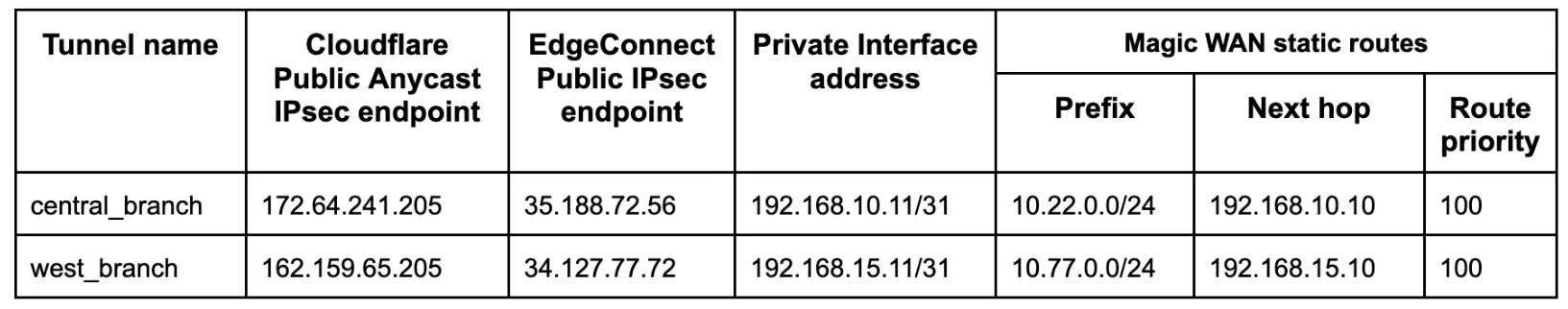
_Note: Labels in this image may reflect a previous product name._
The following example shows the **central\_branch** deployment on the Orchestrator.
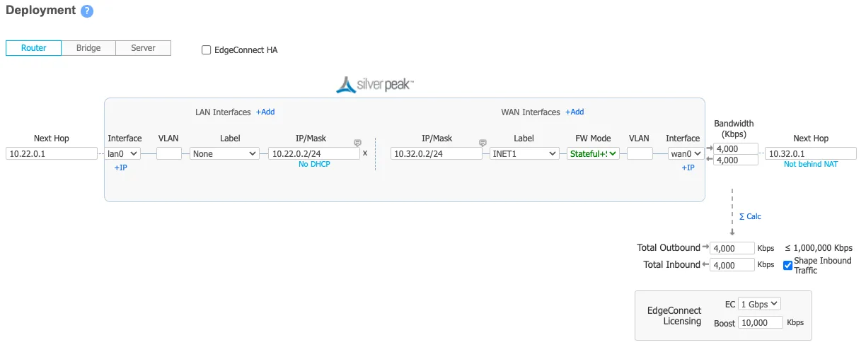
The Deployment screenshot displays several different IP addresses and interfaces. From left to right:
* **Next Hop 10.22.0.1** \- This example uses Google Cloud. This IP defines the default gateway IP for the subnet and is built into GCP.
* **IP/Mask (LAN) 10.22.0.2/24** \- This defines the LAN0 interface IP of the EdgeConnect appliance.
* **IP/Mask (WAN) 10.32.0.2/24** \- This defines the WAN0 interface IP of the EdgeConnect appliance.
* **Next Hop 10.32.0.1** \- This example uses Google Cloud. This IP defines the default gateway IP for the subnet and is built into GCP.
## 1\. Define a common site on the Orchestrator
For all EdgeConnect devices using Cloudflare, modify the devices to put them on the same site. This disables automatic IPsec tunnel creation between the EdgeConnect devices using the same labels for the WAN interfaces in use.
This step is only required if Cloudflare is used for east-west traffic routing.
## 2\. Configure overlay policies
Aruba Orchestrator's Business Intent Overlays create intuitive policies which automatically identify and steer application traffic to Cloudflare. This example creates two Business Intent Overlay (BIO) policies.
GRE tunnel configuration
Cloudflare's [tunnel health checks](https://developers.cloudflare.com/cloudflare-wan/reference/tunnel-health-checks/) are ping reply packets encapsulated in GRE packets. The source IP is the EdgeConnect WAN interface used to establish a tunnel, and the destination IP is Cloudflare servers. These packets need to be sent directly from the WAN interface and not through the established tunnels.
To create the overlay policy:
1. Create a compound application, which is a combination of all [Cloudflare public IPs ↗](https://www.cloudflare.com/ips/) and ICMP packets.
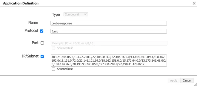
1. Create a breakout Business Intent Overlay (BIO) to bypass the GRE tunnel as the first policy and use this newly created application as the match criteria.
2. Define at least one additional overlay policy and the traffic you want to send to Cloudflare over the GRE tunnels.
The service name used to send traffic through the tunnel created in the next step is **Cloudflare\_GRE**. The example uses **Match Everything** to send all other traffic through the established tunnel (both private east-west traffic & Internet bound north-south traffic through Cloudflare's Secure Web Gateway).
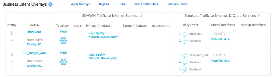
_Note: Labels in this image may reflect a previous product name._
IPsec tunnel configuration
Cloudflare's [tunnel health checks](https://developers.cloudflare.com/cloudflare-wan/reference/tunnel-health-checks/) are ping reply packets encapsulated in IPsec packets. The source IP is the EdgeConnect WAN interface used to establish a tunnel, and the destination IP is Cloudflare servers. These packets need to be sent directly from the WAN interface and not through the established tunnels.
To create the overlay policy:
1. Create a compound application, which is a combination of all [Cloudflare public IPs ↗](https://www.cloudflare.com/ips/) and ICMP packets.

1. Create a breakout Business Intent Overlay (BIO) to bypass the IPsec tunnel as the first policy and use this newly created application as the match criteria.
2. Define at least one additional overlay policy and the traffic you want to send to Cloudflare over the IPsec tunnels.
The service name used to send traffic through the tunnel created in the next step is **Cloudflare\_IPsec**. The example uses **Match Everything** to send all other traffic through the established tunnel (both private east-west traffic and Internet bound north-south traffic through Cloudflare's Secure Web Gateway).
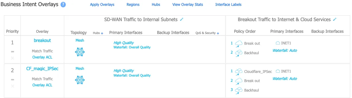
_Note: Labels in this image may reflect a previous product name._
## 3\. Create tunnels on Cloudflare and EdgeConnect
GRE tunnel configuration
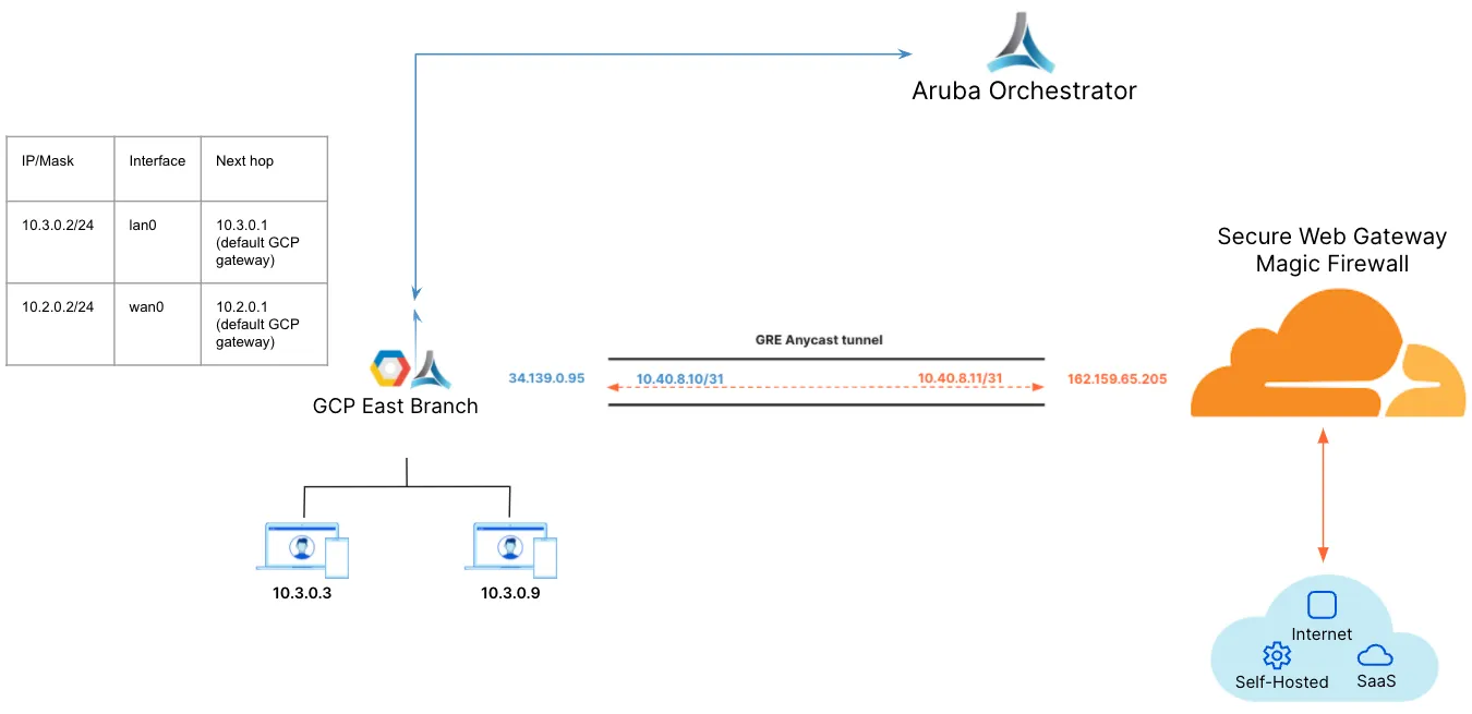
_Note: Labels in this image may reflect a previous product name._
1. Create a tunnel on the EdgeConnect using Cloudflare's assigned public anycast IP and the service used in the overlay policy in the [previous step](#2-configure-overlay-policies).
2. Create a Virtual Tunnel Interface (VTI) using the private IP pair shared with CF GRE tunnel endpoint and the passthrough tunnel to match the newly created tunnel alias (**CF\_GRE\_east** in our example).
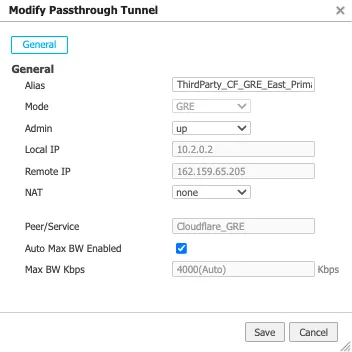
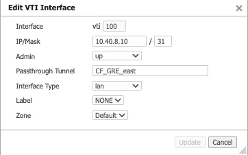
1. Define a GRE tunnel on the Cloudflare dashboard using the EdgeConnect appliance's public IP and the private IP pair /31 shared with the appliance.
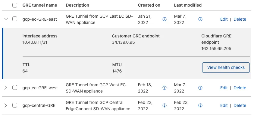
IPsec tunnel configuration
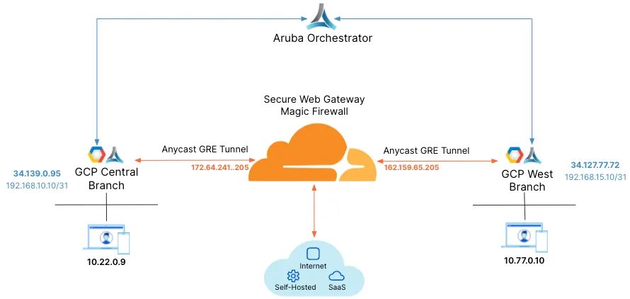
_Note: Labels in this image may reflect a previous product name._
For additional information on creating IPsec tunnels, refer to [API documentation for IPsec tunnels](https://developers.cloudflare.com/api/resources/magic%5Ftransit/subresources/ipsec%5Ftunnels/methods/create/).
* `X-Auth-Email`: Your Cloudflare email ID
* `X-Auth-Key`: Seen in the URL (`dash.cloudflare.com//....`)
* `Account key`: Global API token in Cloudflare dashboard
1. Test new IPsec tunnel creation
Terminal window
```
curl "https://api.cloudflare.com/client/v4/accounts/{account_id}/magic/ipsec_tunnels?validate_only=true" \
--header "X-Auth-Email: " \
--header "X-Auth-Key: " \
--header "Content-Type: application/json" \
--data '{
"ipsec_tunnels": [
{
"name": "EdgeConnect_IPSEC_1",
"customer_endpoint": "35.188.72.56",
"cloudflare_endpoint": "172.64.241.205",
"interface_address": "192.168.10.11/31",
"description": "Tunnel for EdgeConnect - GCP Central"
}
]
}'
```
1. Create a new IPsec tunnel
Terminal window
```
curl https://api.cloudflare.com/client/v4/accounts/{account_id}/magic/ipsec_tunnels \
--header "X-Auth-Email: " \
--header "X-Auth-Key: " \
--header "Content-Type: application/json" \
--data '{
"ipsec_tunnels": [
{
"name": "EdgeConnect_IPSEC_1",
"customer_endpoint": "35.188.72.56",
"cloudflare_endpoint": "172.64.241.205",
"interface_address": "192.168.10.11/31",
"description": "Tunnel for EdgeConnect - GCP Central"
}
]
}'
```
```
{
"result": {
"ipsec_tunnels": [
{
"id": "tunnel_id",
"interface_address": "192.168.10.11/31",
"created_on": "2022-04-14T19:57:43.938376Z",
"modified_on": "2022-04-14T19:57:43.938376Z",
"name": "EdgeConnect_IPSEC_1",
"cloudflare_endpoint": "172.64.241.205",
"customer_endpoint": "35.188.72.56",
"description": "Tunnel for EdgeConnect - GCP Central",
"health_check": {
"enabled": true,
"target": "35.188.72.56",
"type": "reply"
}
}
]
},
"success": true,
"errors": [],
"messages": []
}
```
1. Generate Pre Shared Key (PSK) for tunnel
Use the tunnel ID from the response in Step 2\. Save the pre-shared key generated in this step as you will need it to set up tunnels on the Orchestrator.
Terminal window
```
curl --request POST \
"https://api.cloudflare.com/client/v4/accounts/{account_id}/magic/ipsec_tunnels/{tunnel_id}/psk_generate?validate_only=true" \
--header "X-Auth-Email: " \
--header "X-Auth-Key: "
```
```
{
"result": {
"ipsec_id": "",
"ipsec_tunnel_id": "",
"psk": "XXXXXXXXXXXXXXXXX",
"psk_metadata": {
"last_generated_on": "2022-04-14T20:05:29.756514071Z"
}
},
"success": true,
"errors": [],
"messages": []
}
```
**Create an IPsec tunnel on EdgeConnect**
You can create a tunnel after the Business Intent Overlay policies have been defined. Use the correct policy or service created in [configure overlay policy](#2-configure-overlay-policies). The local IP is the local WAN interface of the EdgeConnect device, and the remote IP is the Cloudflare public IP assigned as the tunnel endpoint.
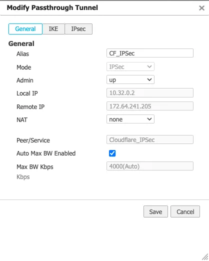
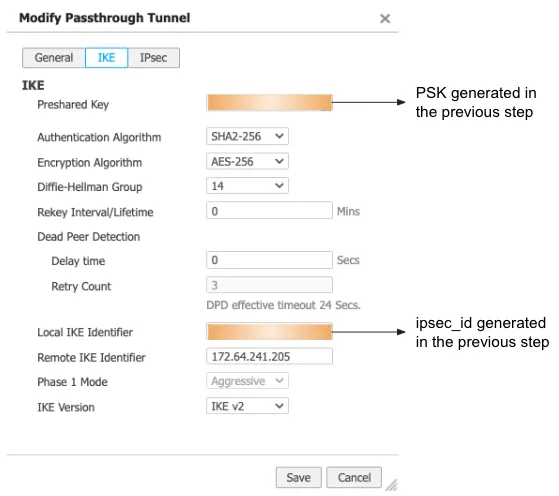
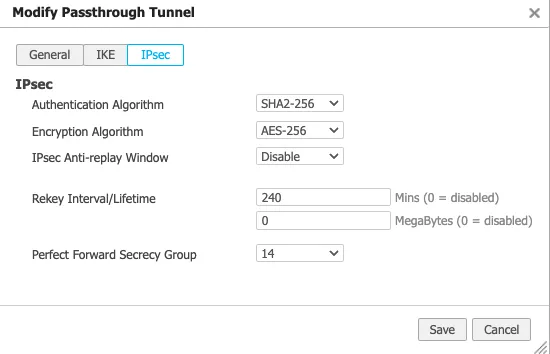
**Create a Virtual Tunnel Interface (VTI) on the EdgeConnect appliance**
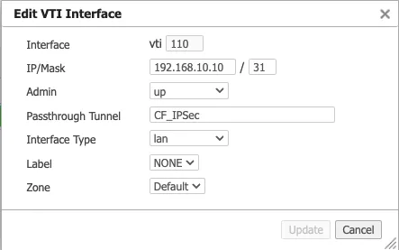
## 4\. Create static routes on Cloudflare and EdgeConnect
GRE tunnel configuration
1. Define static routes on the Cloudflare dashboard for the LAN subnet(s) attached to the EdgeConnect appliance. Use the private IP pair for the EdgeConnect tunnel endpoint.
In this example, the traffic to subnet `10.3.0.0/16` attached to the **east\_branch** EdgeConnect appliance has a next hop of `10.40.8.10`.
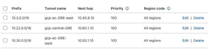
1. Define static routes on the Orchestrator so Cloudflare can route traffic between sites.
This example creates a route for the subnet `10.30.0.0/24` on the **west\_branch** to route via the established GRE tunnel between the EdgeConnect appliance and Cloudflare.
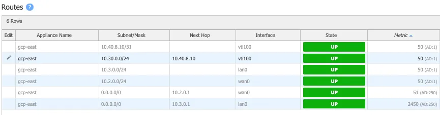
IPsec tunnel configuration
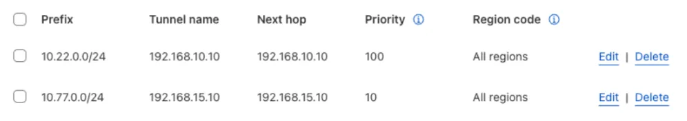
**Static routes for central branch on EdgeConnect**
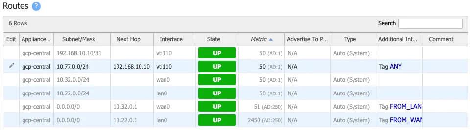
**Static routes for west branch on EdgeConnect**
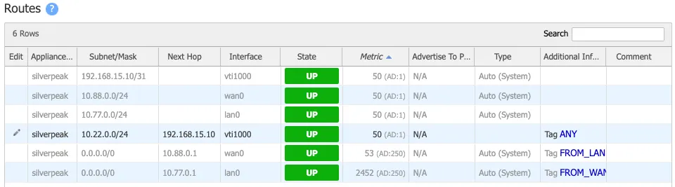
## 5\. Validate traffic flow
GRE tunnel configuration
**Validate Secure Web Gateway**
To validate traffic flow from the local subnet through Cloudflare's Secure Web Gateway, perform a cURL as shown in this example.
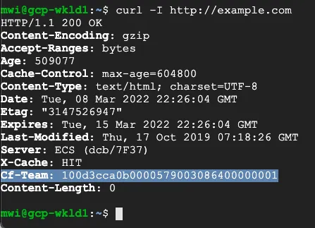
You can validate the request went through Gateway with the presence of the `Cf-Team` response header, or by looking at the logs in the dashboard under **Logs** \> **Gateway** \> **HTTP**.
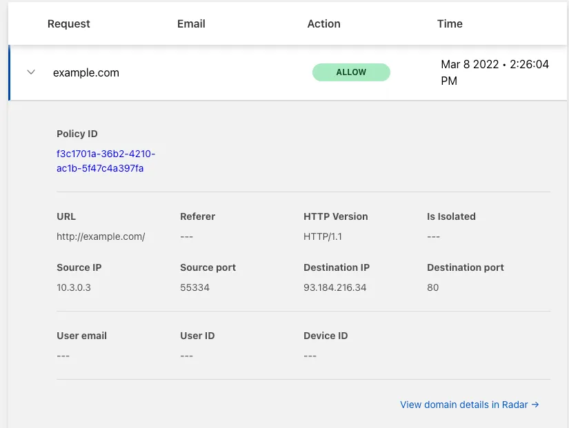
**Validate east-west traffic**
To validate east-west traffic flow, perform a traceroute as shown in the example.
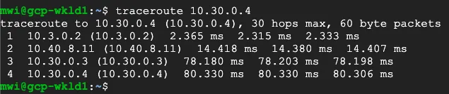
The example shows a client in GCP East (`10.3.0.3`), which can ping the private IP of a client in GCP West (`10.30.0.4`).
The traceroute shows the path going from the client (`10.3.0.3`) to:
* the GCP East lan0 IP on the EdgeConnect (`10.3.0.2`)
* the Cloudflare private GRE endpoint IP (`10.4.8.11`)
* the GCP West lan0 IP on the West EdgeConnect (`10.30.0.3`)
* the GCP West client (`10.30.0.4`)
This validates the east-west traffic flow through Cloudflare WAN.
IPsec tunnel configuration
**Validate Secure Web Gateway**
To validate traffic flow from the local subnet through Cloudflare's Secure Web Gateway, perform a cURL as shown in this example.

You can validate the request went through Secure Web Gateway with the presence of the `Cf-Team` response header or by looking at the logs in the dashboard under **Logs** \> **Gateway** \> **HTTP**.
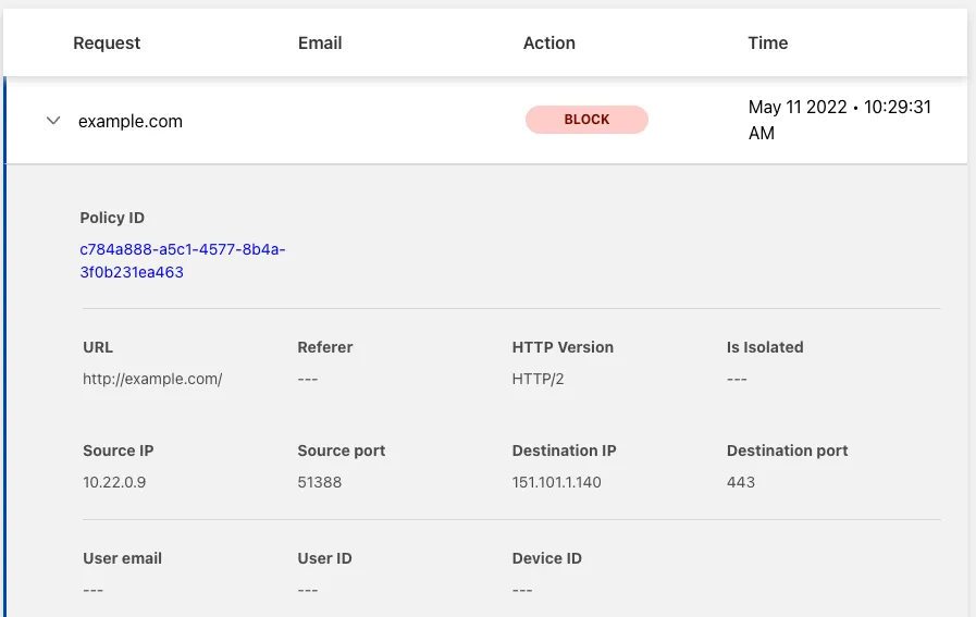
**Validate east-west traffic**
To validate east-west traffic flow, perform a traceroute as shown in the example.
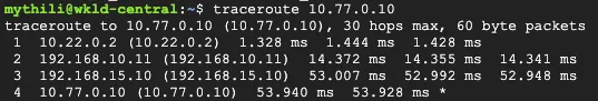
The example shows a client in GCP Central (`10.22.0.9`), which can ping the private IP of a client in GCP West (`10.77.0.10`).
The traceroute shows the path going from the client (`10.22.0.9`) to:
* the GCP Central lan0 IP on the EdgeConnect (`10.22.0.2`)
* the Cloudflare private IPsec endpoint IP (`192.168.10.11`)
* the GCP West EdgeConnect private IPsec endpoint IP (`192.168.15.10`)
* the GCP West client (`10.77.0.10`)
This validates the east-west traffic flow through Cloudflare WAN.
## 6\. Cloudflare policies
At this point, the GRE or IPsec tunnels should be connected from the EdgeConnect appliances to Cloudflare's global network, and traffic is scoped to route over the tunnels using the EdgeConnect Business Intent Overlays.
To begin filtering traffic and gathering analytics, refer to the [Cloudflare Network Firewall documentation](https://developers.cloudflare.com/cloudflare-network-firewall/) to learn how to create filters for east-west inter-branch traffic and the [Secure Web Gateway documentation](https://developers.cloudflare.com/cloudflare-one/traffic-policies/) to learn how to configure Gateway policies if you decide to send traffic from your local private subnets to the Internet through Cloudflare Gateway.
```json
{"@context":"https://schema.org","@type":"BreadcrumbList","itemListElement":[{"@type":"ListItem","position":1,"item":{"@id":"/directory/","name":"Directory"}},{"@type":"ListItem","position":2,"item":{"@id":"/cloudflare-wan/","name":"Cloudflare WAN"}},{"@type":"ListItem","position":3,"item":{"@id":"/cloudflare-wan/configuration/","name":"Configuration"}},{"@type":"ListItem","position":4,"item":{"@id":"/cloudflare-wan/configuration/manually/","name":"Manual configuration"}},{"@type":"ListItem","position":5,"item":{"@id":"/cloudflare-wan/configuration/manually/third-party/","name":"Third-party integration"}},{"@type":"ListItem","position":6,"item":{"@id":"/cloudflare-wan/configuration/manually/third-party/aruba-edgeconnect/","name":"Aruba EdgeConnect Enterprise"}}]}
```
---
---
title: Amazon AWS Transit Gateway
description: This tutorial provides information and examples of how to configure IPsec VPN between Cloudflare WAN (formerly Magic WAN) with an AWS Transit Gateway.
image: https://developers.cloudflare.com/zt-preview.png
---
[Skip to content](#%5Ftop)
Was this helpful?
YesNo
[ Edit page ](https://github.com/cloudflare/cloudflare-docs/edit/production/src/content/docs/cloudflare-wan/configuration/manually/third-party/aws.mdx) [ Report issue ](https://github.com/cloudflare/cloudflare-docs/issues/new/choose)
Copy page
# Amazon AWS Transit Gateway
This tutorial provides information and examples of how to configure IPsec VPN between Cloudflare WAN (formerly Magic WAN) with an AWS Transit Gateway.
## Prerequisites
You need to have an AWS transit gateway created in your AWS account. This is needed to route traffic between your AWS virtual private cloud (VPC) and Cloudflare WAN. Refer to the [AWS documentation ↗](https://docs.aws.amazon.com/vpc/latest/tgw/tgw-getting-started.html) to learn more about creating a transit gateway.
Additionally, you also need to configure the necessary route table entries for the virtual machine (VM) in your VPC, as well as the route table entries for the transit gateway. Otherwise, connectivity between your VM and another VM routed through Cloudflare WAN will not work. Refer to the [AWS documentation ↗](https://docs.aws.amazon.com/vpc/latest/userguide/VPC%5FRoute%5FTables.html) to learn more about routing tables.
## AWS
### Create AWS transit gateway VPN attachment
1. Go to **Transit gateways** \> **Transit gateway attachments**, and select **Create transit gateway attachment**.
2. Select the **Transit gateway ID** that you created previously from the drop-down menu.
3. For **Attachment type**, select _VPN_.
4. Under VPN attachment, select the following settings (you can leave settings not mentioned here with their default values):
1. **Customer Gateway**: Select **New**.
2. **IP Address**: Enter your Cloudflare anycast IP address.
3. **Routing options**: Select **Static**.
5. Select **Create transit gateway attachment**.
### Configure the VPN connection
1. Select the VPN connection you created > **Download configuration**.
2. This action downloads a text file. Search for the IP range that the AWS Transit Gateway assigned your tunnel. The first IP range should be the one used by the AWS Transit Gateway. Use the second IP range to configure your [Interface address](#ipsec-tunnels) in Cloudflare WAN.
3. Select the VPN connection you created > **Actions** \> **Modify VPN tunnel options**.
4. From the **VPN tunnel outside IP address** drop-down menu, select one of the tunnels.
5. Take note of the **IP address** you chose, as this corresponds to the customer endpoint IP that you will need to configure on the Cloudflare side of the IPsec tunnel.
6. The number of options for the VPN connection will expand. Take note of the **Pre-shared key**. You will need it to create the IPsec tunnel on Cloudflare's side.
7. In **Inside IPv4 CIDR**, AWS enforces that only a `/30` block within the `169.254.0.0/16` range can be used. To accommodate this, Cloudflare supports a subset of this IP block. Namely, Cloudflare supports `169.254.240.0/20` to be assigned as the IPsec tunnel's (internal) interface IPs. This example will use `169.254.244.0/30` as the CIDR block for the IPsec tunnel: `169.254.244.1` for the AWS side of the tunnel, and `169.254.244.2` for the Cloudflare side of the tunnel.
Warning
Make sure you input an IP address supported by Cloudflare. If you do not input a value here, AWS will randomly generate an IP address that might not be supported by Cloudflare.
8. Configure the following settings for the IPsec tunnel. Note that the **Startup action** needs to be set to **Start**, which means the AWS side will initiate IPsec negotiation. Settings not mentioned here can be left at their default settings:
* **Phase 1 encryption algorithms**: `AES256-GCM-16`
* **Phase 2 encryption algorithms**: `AES256-GCM-16`
* **Phase 1 integrity algorithms**: `SHA2-256`
* **Phase 2 integrity algorithms**: `SHA2-256`
* **Phase 1 DH group numbers**: `20`
* **Phase 2 DH group numbers**: `20`
* **IKE Version**: `ikev2`
* **Startup action**: **Start**
* **DPD timeout action**: `Restart`
9. Select **Save changes**.
10. Repeat the steps above to configure the second VPN connection. Use the second outside IP address, and make the appropriate changes to IP addresses as well when configuring Cloudflare's side of the tunnel.
Note
ECMP over two VPN tunnels is not supported with a static routing configuration. You will need to configure dynamic routing for the VPN between the transit gateway and the customer gateway device. Refer to [AWS documentation ↗](https://docs.aws.amazon.com/vpc/latest/tgw/tgw-transit-gateways.html) for more information.
## Cloudflare WAN
After configuring the AWS transit gateway VPN connection and the tunnel as mentioned above, go to the Cloudflare dashboard and create the corresponding IPsec tunnel and static routes on the Cloudflare WAN side.
### IPsec tunnels
1. Refer to [Add tunnels](https://developers.cloudflare.com/cloudflare-wan/configuration/manually/how-to/configure-tunnel-endpoints/#add-tunnels) to learn how to add an IPsec tunnel. When creating your IPsec tunnel, make sure you define the following settings:
* **Tunnel name**: `tunnel01`
* **Interface address**: The `/30` CIDR block enforced by AWS (first usable IP is for the AWS side). For example, `169.254.244.2`.
* **Customer endpoint**: The IP address from AWS's VPN tunnel outside IP address. For example, `35.xx.xx.xx`.
* **Cloudflare endpoint**: Enter the first of your two anycast IPs.
* **Pre-shared key**: Select **Use my own pre-shared key**, and enter the PSK you created for the AWS VPN tunnel.
* **Health check type**: Select **Request**
* **Health check direction**: Select **Bidirectional**
* **Replay protection**: Select **Enabled**.
2. Select **Save**.
3. Repeat the above steps for `tunnel02`. Select the same prefix, but select the second IPsec tunnel for **Tunnel/Next hop**.
### Static routes
The static route in Cloudflare WAN should point to the appropriate virtual machine (VM) subnet you created inside your AWS virtual private cloud. For example, if your VM has a subnet of `192.168.192.0/26`, you should use it as the prefix for your static route.
To create a static route:
1. Refer to [Create a static route](https://developers.cloudflare.com/cloudflare-wan/configuration/manually/how-to/configure-routes/#create-a-static-route) to learn how to create one.
2. In **Prefix**, enter the subnet for your VM. For example, `192.xx.xx.xx/24`.
3. For the **Tunnel/Next hop**, select the IPsec tunnel you created in the previous step.
4. Repeat the steps above for the second IPsec tunnel you created.
```json
{"@context":"https://schema.org","@type":"BreadcrumbList","itemListElement":[{"@type":"ListItem","position":1,"item":{"@id":"/directory/","name":"Directory"}},{"@type":"ListItem","position":2,"item":{"@id":"/cloudflare-wan/","name":"Cloudflare WAN"}},{"@type":"ListItem","position":3,"item":{"@id":"/cloudflare-wan/configuration/","name":"Configuration"}},{"@type":"ListItem","position":4,"item":{"@id":"/cloudflare-wan/configuration/manually/","name":"Manual configuration"}},{"@type":"ListItem","position":5,"item":{"@id":"/cloudflare-wan/configuration/manually/third-party/","name":"Third-party integration"}},{"@type":"ListItem","position":6,"item":{"@id":"/cloudflare-wan/configuration/manually/third-party/aws/","name":"Amazon AWS Transit Gateway"}}]}
```
---
---
title: Microsoft Azure Virtual WAN
description: This tutorial provides information on how to connect Cloudflare WAN (formerly Magic WAN) to a Microsoft Azure Virtual WAN hub.
image: https://developers.cloudflare.com/zt-preview.png
---
[Skip to content](#%5Ftop)
Was this helpful?
YesNo
[ Edit page ](https://github.com/cloudflare/cloudflare-docs/edit/production/src/content/docs/cloudflare-wan/configuration/manually/third-party/azure/azure-virtual-wan.mdx) [ Report issue ](https://github.com/cloudflare/cloudflare-docs/issues/new/choose)
Copy page
# Microsoft Azure Virtual WAN
This tutorial provides information on how to connect Cloudflare WAN (formerly Magic WAN) to a Microsoft Azure Virtual WAN hub.
## Prerequisites
You will need to have an existing Resource group, Virtual Network, and Virtual Machine created in your Azure account. Refer to [Microsoft's documentation ↗](https://learn.microsoft.com/en-us/azure/virtual-network/) to learn more on how to create these.
## Start Azure configuration
### 1\. Create a Virtual WAN
To connect one or more VNets to Cloudflare WAN via a Virtual WAN hub, you first need to create a Virtual WAN (vWAN) resource representing your Azure network. If you already have a vWAN that you wish to connect to Cloudflare WAN, continue to the next step. Refer to [Microsoft's documentation ↗](https://learn.microsoft.com/en-us/azure/virtual-wan/virtual-wan-site-to-site-portal#openvwan) to learn more.
1. In the Azure portal, go to your **Virtual WANs** page.
2. Select the option to create a **Virtual WAN**.
3. Create a Virtual WAN with the **Type** set to **Standard**.
### 2\. Create a Virtual WAN Hub
Using traditional hub and spoke terminology, a Virtual WAN Hub deployed within a vWAN is the hub to which your VNet(s) and Cloudflare WAN attach as spokes. The vWAN hub deployed in this step will contain a VPN Gateway for connecting to Cloudflare WAN.
1. Create a **Virtual WAN Hub**.
2. In **Basics**:
1. Select your resource group as well as your desired region, capacity, and hub routing preference. Microsoft recommends using the default hub routing preference of **ExpressRoute** unless you have a specific need to change this setting. Refer to [Microsoft's documentation ↗](https://learn.microsoft.com/en-us/azure/virtual-wan/about-virtual-hub-routing-preference) to learn more about Azure hub routing preferences.
2. Configure the **Hub Private Address Space**. Choose an [address space with a subnet mask of /24 or greater ↗](https://learn.microsoft.com/en-us/azure/virtual-wan/virtual-wan-site-to-site-portal#hub) that does not overlap with the address spaces of any VNets you wish to attach to the vWAN Hub, nor with any of your Cloudflare WAN sites.
3. In **Site to Site**:
1. In **Do you want to create a Site to site (VPN gateway)?** select **Yes**.
2. Select your desired **Gateway scale units** and **Routing Preference**. Refer to [Microsoft's documentation ↗](https://learn.microsoft.com/en-us/azure/virtual-network/ip-services/routing-preference-overview#routing-via-microsoft-global-network) to learn more about Azure routing preferences.
4. Select **Create**. Note that the deployment time for the vWAN Hub and VPN Gateway may take 30 minutes or more.
5. After the VPN Gateway has finished provisioning, go to **Virtual WAN** \> **Hubs** \> **Your vHub** \> **Connectivity** \> **VPN (Site to site)**.
6. In the **Essentials** dropdown select the VPN Gateway listed.
7. Select the JSON View for the VPN Gateway and take note of the JSON attributes at the paths `properties.ipConfigurations[0].publicIpAddress` and `properties.ipConfigurations[1].publicIpAddress`. These will be the customer endpoints needed when configuring IPsec tunnels for Cloudflare WAN.
### 3\. Create a VPN site
A VPN site represents the remote site your Azure vWAN can reach through a VPN connection. This is typically an on-premises location. In this case, the VPN site represents Cloudflare WAN.
1. Go to **Virtual WAN** \> **VPN sites** \> **Create site**.
2. In **Basics**:
1. Configure your desired region and name.
2. Configure the **Device vendor** as Cloudflare.
3. In **Private address space**, specify the address range(s) you wish to access from your vWAN through Cloudflare WAN. This could include other private networks connected to your Cloudflare WAN, or a default route (`0.0.0.0/0`) if you want Internet egress traffic to traverse Cloudflare WAN (that is, to be scanned by Cloudflare Gateway). The address space can be modified after VPN site creation.
3. In **Links**:
1. Configure a single link. Provide a name, speed (in Mbps), and provider name (here, enter `Cloudflare`) for your link. For the **Link IP address**, enter your Cloudflare anycast address. The **BGP address** and **ASN** fields should be left empty. BGP is not supported at the time of writing this tutorial.
4. Select **Create**.
### 4\. Configure VPN site for IPsec tunnel health checks
Cloudflare WAN uses [Tunnel Health Checks](https://developers.cloudflare.com/cloudflare-wan/reference/tunnel-health-checks/) to monitor whether a tunnel is available.
Tunnel health checks make use of ICMP probes sent from the Cloudflare side of the IPsec tunnel to the remote endpoint (Azure). Probes are sent from the tunnel's interface address, which you specify in two places:
* **Cloudflare Dashboard:** In your IPsec tunnel configuration as the address of the virtual tunnel interface (VTI) (so that Cloudflare knows what address to send probes from). Cloudflare requires this address in CIDR notation with a `/31` netmask.
* **Azure Portal:** In your VPN site's address space (so that Azure routes probe responses back over the tunnel). Azure requires this address in CIDR notation with a `/32` netmask.
Cloudflare recommends that you select a unique `/31` subnet ([RFC 1918 — Address Allocation for Private Internets ↗](https://datatracker.ietf.org/doc/html/rfc1918)) for each IPsec tunnel which is treated as a Point-to-Point Link and provides the ideal addressing scheme to satisfy both requirements.
Example:
* Select `169.254.251.137/31` as your unique Point-to-Point Link subnet.
* In the Cloudflare dashboard, set `169.254.251.137/31` as your tunnel's **IPv4 Interface address**. (Refer to [Configure Cloudflare WAN](#configure-cloudflare-wan) below.)
* In the Azure portal, add `169.254.251.137/32` to your VPN site's **Private address space**.
Note
It is important to ensure the subnet selected for the Interface Address does not overlap with any other subnet.
You should also refer to RFC 3021 for more information on using 31-bit prefixes on [IPv4 Point-to-Point Links ↗](https://datatracker.ietf.org/doc/html/rfc3021).
To configure the Address Space for the Local Network Gateway to support Tunnel Health Checks:
1. Go to **Virtual WAN** \> **VPN sites** \> **Your VPN Site** \> **Edit site** to edit the VPN site configured in the previous section.
2. Update the **Private address space** to include two `/32` subnets in CIDR notation as described above. When using Azure VPN Gateways with vWAN Hubs, a single VPN Gateway Connection maps to two Cloudflare WAN IPsec Tunnels. For this reason, we need to select two unique `/31` subnets, one for each Cloudflare IPsec Tunnel. The upper address of each `/31` is then added to the VPN Site's Private address space as a `/32`subnet.
3. Select **Confirm**.
### 5\. Create a Virtual Network Connection
To connect your existing VNet to your newly created vHub:
1. Go to **Virtual WAN** \> **Virtual network connections** and select **Add connection**.
2. Configure the connection to connect the desired VNet to the vHub created above.
3. Ensure that within the connection's **Routing configuration**:
1. **Propagate to none** is set to **No.**
2. **Bypass Next Hop IP for workloads within this VNet** is set to **No**
3. And **Propagate static route** is set to **Yes**.
4. Select **Create**.
## Configure Cloudflare WAN
When connecting your Azure vHub VPN Gateway to Cloudflare WAN, you need to create two Cloudflare WAN IPsec tunnels to map to the single Azure VPN Gateway Connection created above. This is because Azure VPN Gateways are deployed with two public IP addresses.
1. Create an [IPsec tunnel](https://developers.cloudflare.com/cloudflare-wan/configuration/manually/how-to/configure-tunnel-endpoints/#add-tunnels) in the Cloudflare dashboard.
2. Make sure you have the following settings:
1. **Interface address**: Add the upper IP address within the first `/31` subnet selected in step 4 of the Start Azure Configuration section. Refer to [Tunnel endpoints](https://developers.cloudflare.com/cloudflare-wan/configuration/manually/how-to/configure-tunnel-endpoints/) for more details.
2. **Customer endpoint**: The first public IP associated with your Azure VPN Gateway. For example, `40.xxx.xxx.xxx`.
3. **Cloudflare endpoint**: Use one of the Cloudflare anycast addresses assigned to your account, available in [Leased IPs ↗](https://dash.cloudflare.com/?to=/:account/ip-addresses/address-space). This will also be the IP address corresponding to the VPN Site in Azure. For example, `162.xxx.xxx.xxx`.
4. **Health check rate**: Medium (default).
5. **Health check type**: Reply (default).
6. **Health check direction**: Bidirectional (default).
7. **Health check target**: Custom; enter the customer endpoint.
8. **Add pre-shared key later**: Select this option to create a PSK that will be used later in Azure.
9. **Replay protection**: **Enable**.
3. Edit the tunnel. Generate a new pre-shared key and copy the key to a safe location.
4. Create static routes for your Azure Virtual Network subnets, specifying the newly created tunnel as the next hop.
5. Create the second IPsec tunnel in the Cloudflare dashboard. Copy the configuration of the first tunnel with the following exceptions:
1. **Interface address**: Add the upper IP address within the **second** `/31` subnet selected in step 4 of the Start Azure Configuration section.
2. **Customer endpoint**: The **second** Public IP associated with your Azure VPN Gateway.
3. **Health check target**: Enter the new customer endpoint as a custom target.
4. **Use my own pre-shared key**: Select this option and enter the key generated for the first tunnel.
6. Create static routes for your Azure Virtual Network subnets, specifying the newly created tunnel as the next hop. To use one tunnel as primary and the other as backup, give the primary tunnel's route a lower priority. To ECMP load balance across both tunnels, assign both routes the same priority.
## Finish Azure Configuration
### 1\. Create an IPsec VPN Gateway Connection
To create a **VPN Gateway Connection**:
1. Go to **Virtual WAN** \> **Hubs** \> **Your vHub** \> **Connectivity** \> **VPN (Site to site)** and remove the default filter **Hub association: Connected** to display the **VPN Site** created above.
2. Check the box next to your VPN Site and select **Connect VPN sites**.
Choose the following settings. These settings have been tested by Cloudflare. However, when setting up your VPN connection note that there are other configuration parameters are also technically feasible, as documented in the [Azure documentation ↗](https://learn.microsoft.com/en-us/azure/virtual-wan/virtual-wan-ipsec) and in the [Cloudflare documentation](https://developers.cloudflare.com/cloudflare-wan/reference/gre-ipsec-tunnels/#supported-configuration-parameters).
1. **PSK**: Provide the PSK generated by Cloudflare for your IPsec tunnels.
2. **Protocol**: _IKEv2_
3. **IPsec**: _Custom_
1. **IPsec SA lifetime in seconds**: 28800
2. **IKE Phase 1**
1. **Encryption**: _AES256_
2. **Integrity/PRF**: _SHA256_
3. **DH Group**: _ECP384_
3. **IKE Phase 2(IPsec)**
1. **IPsec Encryption**: _AES256_
2. **IPsec Integrity**: _SHA256_
3. **PFS Group**: _ECP384_
4. **Propagate Default Route:** **Disable**
5. **Use policy based traffic selector**: **Disable**
6. **Connection mode**: **Initiator Only**
7. **Configure traffic selector?**: **Disabled**
4. Select **Connect**.
```json
{"@context":"https://schema.org","@type":"BreadcrumbList","itemListElement":[{"@type":"ListItem","position":1,"item":{"@id":"/directory/","name":"Directory"}},{"@type":"ListItem","position":2,"item":{"@id":"/cloudflare-wan/","name":"Cloudflare WAN"}},{"@type":"ListItem","position":3,"item":{"@id":"/cloudflare-wan/configuration/","name":"Configuration"}},{"@type":"ListItem","position":4,"item":{"@id":"/cloudflare-wan/configuration/manually/","name":"Manual configuration"}},{"@type":"ListItem","position":5,"item":{"@id":"/cloudflare-wan/configuration/manually/third-party/","name":"Third-party integration"}},{"@type":"ListItem","position":6,"item":{"@id":"/cloudflare-wan/configuration/manually/third-party/azure/","name":"Microsoft Azure"}},{"@type":"ListItem","position":7,"item":{"@id":"/cloudflare-wan/configuration/manually/third-party/azure/azure-virtual-wan/","name":"Microsoft Azure Virtual WAN"}}]}
```
---
---
title: Microsoft Azure VPN Gateway
description: This tutorial provides information on how to connect Cloudflare WAN (formerly Magic WAN) to your Azure Virtual Network, using the Azure Virtual Network Gateway.
image: https://developers.cloudflare.com/zt-preview.png
---
[Skip to content](#%5Ftop)
Was this helpful?
YesNo
[ Edit page ](https://github.com/cloudflare/cloudflare-docs/edit/production/src/content/docs/cloudflare-wan/configuration/manually/third-party/azure/azure-vpn-gateway.mdx) [ Report issue ](https://github.com/cloudflare/cloudflare-docs/issues/new/choose)
Copy page
# Microsoft Azure VPN Gateway
This tutorial provides information on how to connect Cloudflare WAN (formerly Magic WAN) to your Azure Virtual Network, using the Azure Virtual Network Gateway.
## Prerequisites
You will need to have an existing Resource group, Virtual Network, and Virtual Machine created in your Azure account. Refer to [Microsoft's documentation ↗](https://learn.microsoft.com/en-us/azure/virtual-network/) to learn more on how to create these.
## Configure Azure Virtual Network Gateway
### 1\. Create a Gateway subnet
You should already have a Virtual Network (VNET) created with a subnet assigned to it. The next step is to create a gateway subnet that Azure will use for addressing services related to Azure's Virtual Network Gateway. If you already have a gateway subnet, Azure will prevent you from creating a second one. If that is your case, update your gateway subnet settings.
1. Go to your **Virtual Network** \> **Subnets**.
2. Select the option to add a **Gateway subnet**.
3. Configure the subnet address range. The gateway subnet must be contained by the address space of the virtual network, and have a subnet mask of `/27` or greater.
4. Make sure all other settings are set to **None**.
### 2\. Create a Virtual Network Gateway
The Virtual Network Gateway is used to form the tunnel to the devices on your premises.
Note
This configuration guide applies to Azure Virtual Network Gateway which includes the functionality found in the Azure VPN Gateway.
Active/Active and Active/Standby configurations are both supported. Two Azure public IP addresses and two Cloudflare WAN IPsec tunnels are required for the Active/Active configuration.
#### Active/Active configuration
1. Create a Virtual Network Gateway.
2. Create two new public IP addresses or use existing IPs. Take note of the public IP addresses assigned to the Virtual Network Gateway as these will be the **Customer endpoint** for Cloudflare WAN's IPsec tunnels configuration.
3. Navigate to the Virtual Network Gateway created earlier.
4. In **Configuration**, enable **Active-active mode** and disable **Gateway Private IPs**.
5. Select **Create**.
#### Active/Standby configuration
1. Create a Virtual Network Gateway.
2. Create a new public IP address or use an existing IP. Take note of the public IP address assigned to the Virtual Network Gateway as this will be the **Customer endpoint** for Cloudflare WAN's IPsec tunnels configuration.
3. Select the resource group and VNET you have already created.
4. In **Configuration**, disable **Active-active mode** and **Gateway Private IPs**.
5. Select **Create**.
Note
The time it takes for Azure to fully provision the Virtual Network Gateway depends on the deployment region.
## Configure Cloudflare WAN
1. Create an [IPsec tunnel](https://developers.cloudflare.com/cloudflare-wan/configuration/manually/how-to/configure-tunnel-endpoints/#add-tunnels) in the Cloudflare dashboard.
2. Make sure you have the following settings:
1. **Interface address**: As the Azure Local Network Gateway will only permit specifying the lower IP address in a `/31` subnet, add the upper IP address within the `/31` subnet. You will configure the corresponding `/32` address in Azure in a later step (refer to [Configure Local Network Gateway for IPsec tunnel health checks](#2-configure-local-network-gateway-for-ipsec-tunnel-health-checks)). Refer to [Tunnel endpoints](https://developers.cloudflare.com/cloudflare-wan/configuration/manually/how-to/configure-tunnel-endpoints/) for more details.
2. **Customer endpoint**: The Public IP associated with your Azure Virtual Network Gateway. For example, `40.xxx.xxx.xxx`.
3. **Cloudflare endpoint**: Use one of the Cloudflare anycast addresses assigned to your account, available in [Leased IPs ↗](https://dash.cloudflare.com/?to=/:account/ip-addresses/address-space). This will also be the IP address corresponding to the Local Network Gateway in Azure. For example, `162.xxx.xxx.xxx`.
4. **Health check rate**: Leave the default option (Medium) selected.
5. **Health check type**: Leave the default option (Reply) selected.
6. **Health check direction**: Leave default option (Bidirectional) selected.
7. **Health check target**: Select **Custom**.
8. **Target address**: Enter the same address that is used in the **Customer endpoint** field.
9. **Add pre-shared key later**: Select this option to create a PSK that will be used later in Azure.
10. **Replay protection**: **Enable**.
3. If you are using the Active/Active configuration, select **Add IPsec tunnel** and repeat step 2 to create the second Cloudflare WAN IPsec tunnel. Use the same **Cloudflare endpoint** as for the first tunnel.
4. Select **Add Tunnels** when you are finished.
5. The Cloudflare dashboard will show you a list of your tunnels. Edit the tunnel(s) you have created > select **Generate a new pre-shared key** \> copy the generated key. If using the Active/Active configuration, select **Change to a new custom pre-shared key** on the second tunnel and use the PSK generated for the first tunnel.
6. Create [static routes](https://developers.cloudflare.com/cloudflare-wan/configuration/manually/how-to/configure-routes/#create-a-static-route) for your Azure Virtual Network subnets, specifying the newly created tunnel as the next hop.
Note
Both tunnels in an Active/Active configuration must use the same **Cloudflare endpoint**, because an Active/Active Azure VPN connection creates two tunnels to the same remote address.
## Complete the Azure Configuration
### 1\. Create a Local Network Gateway
The Local Network Gateway typically refers to your on-premises location. In this case, the Local Network Gateway represents the Cloudflare side of the connection.
We recommend creating a Local Network Gateway for your Cloudflare IPsec tunnel.
1. Create a new local network gateway.
2. In **Instance details** \> **Endpoint**, select **IP address** and enter the Cloudflare anycast address in the IP address field.
3. In **Address space(s)**, specify the address range of any subnets you wish to access remotely through the Cloudflare WAN connection. For example, if you want to reach a network with an IP range of `192.168.1.0/24`, and this network is connected to your Cloudflare WAN tenant, you would add `192.168.1.0/24` to the local network gateway address space.
4. Go to the **Advanced** tab > **BGP settings**, and make sure you select **No**.
Note
A single Cloudflare anycast address must be used in both Active/Active and Active/Standby configurations.
### 2\. Configure Local Network Gateway for IPsec tunnel health checks
Cloudflare WAN uses [Tunnel Health Checks](https://developers.cloudflare.com/cloudflare-wan/reference/tunnel-health-checks/) to monitor whether a tunnel is available.
Tunnel health checks make use of ICMP probes sent from the Cloudflare side of the IPsec tunnel to the remote endpoint (Azure). Probes are sent from the tunnel's interface address, which you specify in two places:
1. **Cloudflare Dashboard:** In your IPsec tunnel configuration as the address of the virtual tunnel interface (VTI) (so that Cloudflare knows what address to send probes from). Cloudflare requires this address in Classless Inter-Domain Routing (CIDR) notation with a `/31` netmask.
2. **Azure Portal:** In your VPN site's address space (so that Azure routes probe responses back over the tunnel). Azure requires this address in CIDR notation with a `/32` netmask.
Cloudflare recommends customers select a unique `/31` subnet ([RFC 1918 - Address Allocation for Private Internets ↗](https://datatracker.ietf.org/doc/html/rfc1918)) for each IPsec tunnel which is treated as a Point-to-Point Link and provides the ideal addressing scheme to satisfy both requirements.
Example:
* Select 10.252.3.55/31 as your unique point-to-point link subnet.
* In the Cloudflare dashboard, set `10.252.3.55/31` as your tunnel's **IPv4 Interface address** (refer to [Configure Cloudflare WAN](#configure-cloudflare-wan)).
* In the Azure portal, add `10.252.3.55/32` to your Local Network Gateway's **Address space**.
Note
It is important to ensure the subnet selected for the Interface Address does not overlap with any other subnet.
Note
Refer to RFC 3021 for more information on using 31-bit prefixes on [IPv4 Point-to-Point Links ↗](https://datatracker.ietf.org/doc/html/rfc3021).
To configure the Address Space for the Local Network Gateway to support Tunnel Health Checks:
1. Edit the Local Network Gateway configured in the previous section.
2. Select **Connections**.
3. Under **Address Space(s)** add the Interface Address of the IPsec Tunnel from the Cloudflare dashboard in CIDR notation (for example, `10.252.3.55/32`).
4. If using an Active/Active configuration, also add the Interface Address of the second IPsec Tunnel from the Cloudflare Dashboard in CIDR notation (for example, `10.252.3.56/32`) under **Address Space(s)**. Both tunnel interface addresses must be configured in the Local Network Gateway Address Space to ensure both tunnels remain healthy.
5. Select **Save**.
Note
The IPsec Tunnel Interface Address should be entered as a `/31` in the Cloudflare Dashboard, but as a `/32` when configuring the Local Network Gateway Address Space(s) in the Azure portal.
### 3\. Create an IPsec VPN Connection
Choose the following settings when creating your VPN Connection:
1. **Virtual network gateway**: Select the Virtual Network Gateway you created in [Create a Virtual Network Gateway](#2-create-a-virtual-network-gateway).
2. **Local network gateway**: Select the Local Network Gateway created in [Create a Local Network Gateway](#1-create-a-local-network-gateway).
3. **Use Azure Private IP Address**: **Disabled**
4. **BGP**: **Disabled**
5. **IPsec / IKE policy**: **Custom**
1. **IKE Phase 1**
1. **Encryption**: _GCMAES256_
2. **Integrity/PRF**: _SHA384_
3. **DH Group**: _ECP384_
2. **IKE Phase 2(IPsec)**
1. **IPsec Encryption**: _GCMAES256_
2. **IPsec Integrity**: _GCMAES256_
3. **PFS Group**: _ECP384_
3. **IPsec SA lifetime in KiloBytes**: `0`
4. **IPsec SA lifetime in seconds**: `28800`
5. **Use policy based traffic selector**: **Disable**
6. **DPD timeout in seconds**: `45`
7. **Connection mode**: **InitiatorOnly**
8. **Use custom traffic selectors**: **Disabled**
6. After the connection is created, select **Settings** \> **Authentication**, and input your PSK (this will need to match the PSK used by the Cloudflare WAN configuration).
Repeat this process to define the settings for the Connection to the Local Network Gateway that corresponds to the redundant Cloudflare anycast IP address.
### 4\. Route all Internet traffic through Cloudflare WAN and Cloudflare Gateway
Cloudflare Zero Trust customers can route Internet-bound traffic through Cloudflare WAN to the Internet through Cloudflare Gateway.
Microsoft does not permit specifying a default route (`0.0.0.0/0`) under Address Space in the Local Network Gateway. However, it is possible to work around this limitation through the use of route summarization.
1. Go to **Local network gateways** and select the desired object.
2. Go to **Configuration** \> **Address Space(s)** and specify the following two subnets: `0.0.0.0/1` & `128.0.0.0/1`.
3. Do not remove the subnet configured to support the Tunnel Health Checks.
4. Select **Save**.
## Install Cloudflare Zero Trust CA Certificate
If you opt to route all Internet bound traffic through Cloudflare WAN and want to take advantage of [HTTPS TLS decryption](https://developers.cloudflare.com/cloudflare-one/traffic-policies/http-policies/tls-decryption/), it will be necessary to install and trust the Cloudflare Zero Trust root certificate authority (CA) certificate on your user's devices. You can either install the certificate provided by Cloudflare (default option), or generate your own custom certificate and upload it to Cloudflare.
More details on how to install the root CA certificate can be found in [User-side certificates](https://developers.cloudflare.com/cloudflare-one/team-and-resources/devices/user-side-certificates/) in the Cloudflare Zero Trust documentation.
Once the root CA certificate is installed, open a web browser or use curl to validate Internet connectivity:
Terminal window
```
curl https://ipinfo.io
```
```
{
"ip": "104.xxx.xxx.225",
"city": "Reston",
"region": "Virginia",
"country": "US",
"loc": "xx.xxxx,-xx.xxxx",
"org": "AS13335 Cloudflare, Inc.",
"postal": "20190",
"timezone": "America/New_York",
"readme": "https://ipinfo.io/missingauth"
}
```
Note
Internet Control Message Protocol (ICMP) (ping/traceroute) will work to remote Cloudflare WAN sites, but is not forwarded to the Internet. Ensure you validate connectivity via HTTP.
## Validate connectivity and disable Azure Virtual Network Gateway anti-replay protection
Once you have determined that connectivity has been established, Cloudflare recommends you disable anti-replay protection for the Azure Virtual Network Gateway site-to-site VPN connection. This can be accomplished through Microsoft Azure API.
1. Determine the API token via PowerShell:
PowerShell
```
Get-AzAccessToken
```
```
Token: eyJ0eAH-PdSPg
ExpiresOn : 04/08/2024 23:32:47 +00:00
Type : Bearer
TenantId : xxxxxxxx-xxxx-xxxx-xxxx-xxxxxxxxxxxx
UserId : user@domain.com
```
1. Issue the API call to display the details of the site-to-site VPN Connection associated with the Azure Virtual Network Gateway (`GET` request):
Terminal window
```
curl --location 'https://management.azure.com/subscriptions/{{subscriptionId}}/resourceGroups/{{resourceGroupName}}/providers/Microsoft.Network/virtualNetworkGateways/{{virtualNetworkGatewayName}}?api-version=2022-05-01' \
--header 'Authorization: Bearer eyJ0eAH-PdSPg'
```
1. Copy/paste the entire response into a text editor:
```
{
"name": "{{virtualNetworkGatewayName}}",
"id": "/subscriptions/{{subscriptionId}}/resourceGroups/{{resourceGroupName}}/providers/Microsoft.Network/virtualNetworkGateways/{{virtualNetworkGatewayName}}",
"etag": "W/\"xxxxxxxx-xxxx-xxxx-xxxx-xxxxxxxxxxxx\"",
"type": "Microsoft.Network/virtualNetworkGateways",
"location": "eastus"
},
"properties": {
"provisioningState": "Succeeded",
"resourceGuid": "xxxxxxxx-xxxx-xxxx-xxxx-xxxxxxxxxxxx",
"packetCaptureDiagnosticState": "None",
"enablePrivateIpAddress": false,
"isMigrateToCSES": false,
"ipConfigurations": [
{
"name": "default",
"id": "/subscriptions/{{subscriptionId}}/resourceGroups/{{resourceGroupName}}/providers/Microsoft.Network/virtualNetworkGateways/{{virtualNetworkGatewayName}}/ipConfigurations/default",
"etag": "W/\"xxxxxxxx-xxxx-xxxx-xxxx-xxxxxxxxxxxx\"",
"type": "Microsoft.Network/virtualNetworkGateways/ipConfigurations",
"properties": {
"provisioningState": "Succeeded",
"privateIPAllocationMethod": "Dynamic",
"publicIPAddress": {
"id": "/subscriptions/{{subscriptionId}}/resourceGroups/{{resourceGroupName}}/providers/Microsoft.Network/publicIPAddresses/{{virtualNetworkGatewayPublicIpAddress}}"
},
"subnet": {
"id": "/subscriptions/{{subscriptionId}}/resourceGroups/{{resourceGroupName}}/providers/Microsoft.Network/virtualNetworks/{{virtualNetworkGatewayName}}/subnets/GatewaySubnet"
}
}
}
],
"natRules": [],
"virtualNetworkGatewayPolicyGroups": [],
"enableBgpRouteTranslationForNat": false,
"disableIPSecReplayProtection": false,
"sku": {
"name": "VpnGw2AZ",
"tier": "VpnGw2AZ",
"capacity": 2
},
"gatewayType": "Vpn",
"vpnType": "RouteBased",
"enableBgp": false,
"activeActive": false,
"bgpSettings": {
"asn": 65515,
"bgpPeeringAddress": "172.25.40.30",
"peerWeight": 0,
"bgpPeeringAddresses": [
{
"ipconfigurationId": "/subscriptions/{{subscriptionId}}/resourceGroups/{{resourceGroupName}}/providers/Microsoft.Network/virtualNetworkGateways/{{virtualNetworkGatewayName}}/ipConfigurations/default",
"defaultBgpIpAddresses": [
"172.25.40.30"
],
"customBgpIpAddresses": [],
"tunnelIpAddresses": [
"{{CF ANYCAST IP}}"
]
}
]
},
"gatewayDefaultSite": {
"id": "/subscriptions/{{subscriptionId}}/resourceGroups/{{resourceGroupName}}/providers/Microsoft.Network/localNetworkGateways/{{localNetworkGatewayName}}"
},
"vpnGatewayGeneration": "Generation2",
"allowRemoteVnetTraffic": false,
"allowVirtualWanTraffic": false
}
}
```
1. Locate the line that controls disabling IPsec anti-replay protection, and change it from `false` to `true`:
```
"disableIPSecReplayProtection": true
```
1. Upload the entire response in a subsequent API call (`PUT` request):
Terminal window
```
curl --location --request PUT \
'https://management.azure.com/subscriptions/{{subscriptionId}}/resourceGroups/{{resourceGroupName}}/providers/Microsoft.Network/virtualNetworkGateways/{{virtualNetworkGatewayName}}?api-version=2022-05-01' \
--header "Authorization: Bearer eyJ0eAH-PdSPg" \
--header "Content-Type: application/json" \
--data '{
"name": "{{virtualNetworkGatewayName}}",
"id": "/subscriptions/{{subscriptionId}}/resourceGroups/{{resourceGroupName}}/providers/Microsoft.Network/virtualNetworkGateways/{{virtualNetworkGatewayName}}",
"etag": "W/\"xxxxxxxx-xxxx-xxxx-xxxx-xxxxxxxxxxxx\"",
"type": "Microsoft.Network/virtualNetworkGateways",
"location": "eastus"
},
"properties": {
"provisioningState": "Succeeded",
"resourceGuid": "xxxxxxxx-xxxx-xxxx-xxxx-xxxxxxxxxxxx",
"packetCaptureDiagnosticState": "None",
"enablePrivateIpAddress": false,
"isMigrateToCSES": false,
"ipConfigurations": [
{
"name": "default",
"id": "/subscriptions/{{subscriptionId}}/resourceGroups/{{resourceGroupName}}/providers/Microsoft.Network/virtualNetworkGateways/{{virtualNetworkGatewayName}}/ipConfigurations/default",
"etag": "W/\"xxxxxxxx-xxxx-xxxx-xxxx-xxxxxxxxxxxx\"",
"type": "Microsoft.Network/virtualNetworkGateways/ipConfigurations",
"properties": {
"provisioningState": "Succeeded",
"privateIPAllocationMethod": "Dynamic",
"publicIPAddress": {
"id": "/subscriptions/{{subscriptionId}}/resourceGroups/{{resourceGroupName}}/providers/Microsoft.Network/publicIPAddresses/{{virtualNetworkGatewayPublicIpAddress}}"
},
"subnet": {
"id": "/subscriptions/{{subscriptionId}}/resourceGroups/{{resourceGroupName}}/providers/Microsoft.Network/virtualNetworks/{{virtualNetworkGatewayName}}/subnets/GatewaySubnet"
}
}
}
],
"natRules": [],
"virtualNetworkGatewayPolicyGroups": [],
"enableBgpRouteTranslationForNat": false,
"disableIPSecReplayProtection": true,
"sku": {
"name": "VpnGw2AZ",
"tier": "VpnGw2AZ",
"capacity": 2
},
"gatewayType": "Vpn",
"vpnType": "RouteBased",
"enableBgp": false,
"activeActive": false,
"bgpSettings": {
"asn": 65515,
"bgpPeeringAddress": "172.25.40.30",
"peerWeight": 0,
"bgpPeeringAddresses": [
{
"ipconfigurationId": "/subscriptions/{{subscriptionId}}/resourceGroups/{{resourceGroupName}}/providers/Microsoft.Network/virtualNetworkGateways/{{virtualNetworkGatewayName}}/ipConfigurations/default",
"defaultBgpIpAddresses": [
"172.25.40.30"
],
"customBgpIpAddresses": [],
"tunnelIpAddresses": [
"{{CF ANYCAST IP}}"
]
}
]
},
"gatewayDefaultSite": {
"id": "/subscriptions/{{subscriptionId}}/resourceGroups/{{resourceGroupName}}/providers/Microsoft.Network/localNetworkGateways/{{localNetworkGatewayName}}"
},
"vpnGatewayGeneration": "Generation2",
"allowRemoteVnetTraffic": false,
"allowVirtualWanTraffic": false
}
}'
```
1. Leave the replay protection setting checked in the Cloudflare dashboard, and wait several minutes before validating connectivity again.
```json
{"@context":"https://schema.org","@type":"BreadcrumbList","itemListElement":[{"@type":"ListItem","position":1,"item":{"@id":"/directory/","name":"Directory"}},{"@type":"ListItem","position":2,"item":{"@id":"/cloudflare-wan/","name":"Cloudflare WAN"}},{"@type":"ListItem","position":3,"item":{"@id":"/cloudflare-wan/configuration/","name":"Configuration"}},{"@type":"ListItem","position":4,"item":{"@id":"/cloudflare-wan/configuration/manually/","name":"Manual configuration"}},{"@type":"ListItem","position":5,"item":{"@id":"/cloudflare-wan/configuration/manually/third-party/","name":"Third-party integration"}},{"@type":"ListItem","position":6,"item":{"@id":"/cloudflare-wan/configuration/manually/third-party/azure/","name":"Microsoft Azure"}},{"@type":"ListItem","position":7,"item":{"@id":"/cloudflare-wan/configuration/manually/third-party/azure/azure-vpn-gateway/","name":"Microsoft Azure VPN Gateway"}}]}
```
---
---
title: Cisco IOS XE
description: This tutorial contains a configuration example for setting up an Internet Protocol Security (IPsec) tunnel between Cisco IOS XE and Cloudflare. For this tutorial, the tested Cisco IOS XE software was version 17.03.07.
image: https://developers.cloudflare.com/zt-preview.png
---
[Skip to content](#%5Ftop)
Was this helpful?
YesNo
[ Edit page ](https://github.com/cloudflare/cloudflare-docs/edit/production/src/content/docs/cloudflare-wan/configuration/manually/third-party/cisco-ios-xe.mdx) [ Report issue ](https://github.com/cloudflare/cloudflare-docs/issues/new/choose)
Copy page
# Cisco IOS XE
This tutorial contains a configuration example for setting up an Internet Protocol Security (IPsec) tunnel between Cisco IOS XE and Cloudflare. For this tutorial, the tested Cisco IOS XE software was version 17.03.07.
You should replace peer addresses with the anycast IP addresses assigned to your account, available in [Leased IPs ↗](https://dash.cloudflare.com/?to=/:account/ip-addresses/address-space). For example:
* **Anycast 01**: `162.159.###.###`
* **Anycast 02**: `172.64.###.###`
## Cisco IOS XE configuration example
```
crypto ikev2 proposal CF_MAGIC_WAN_IKEV2_PROPOSAL
encryption aes-cbc-256
integrity sha512 sha384 sha256
group 20
!
crypto ikev2 policy CF_MAGIC_WAN_IKEV2_POLICY
match fvrf any
proposal CF_MAGIC_WAN_IKEV2_PROPOSAL
!
crypto ikev2 keyring CF_MAGIC_WAN_KEYRING
peer CF_MAGIC_WAN_IPSEC01
address 162.159.###.###
pre-shared-key hbGnJzFMqwltb###############BapXCOwsGZz2NMg
!
peer CF_MAGIC_WAN_IPSEC02
address 172.64.###.###
pre-shared-key 1VscPp0LPFAcZ###############HOdN-1cUgKVduL4
!
!
!
crypto ikev2 profile CF_MAGIC_WAN_01
match identity remote address 162.159.###.### 255.255.255.255
identity local fqdn ad329f56###############bbe898c0a0.33145236.ipsec.cloudflare.com
authentication remote pre-share
authentication local pre-share
keyring local CF_MAGIC_WAN_KEYRING
no config-exchange request
!
crypto ikev2 profile CF_MAGIC_WAN_02
match identity remote address 172.64.###.### 255.255.255.255
identity local fqdn 83f9c418###############29b3f97049.33145236.ipsec.cloudflare.com
authentication remote pre-share
authentication local pre-share
keyring local CF_MAGIC_WAN_KEYRING
no config-exchange request
!
!
!
!
crypto ipsec profile CF_MAGIC_WAN_01
set security-association lifetime kilobytes disable
set security-association replay disable
set pfs group20
set ikev2-profile CF_MAGIC_WAN_01
!
crypto ipsec profile CF_MAGIC_WAN_02
set security-association lifetime kilobytes disable
set security-association replay disable
set pfs group14
set ikev2-profile CF_MAGIC_WAN_02
!
!
!
!
interface Tunnel101
ip address 10.252.2.35 255.255.255.254
ip mtu 1450
ip tcp adjust-mss 1350
tunnel source 10.141.0.9
tunnel mode ipsec ipv4
tunnel destination 162.159.###.###
tunnel path-mtu-discovery
tunnel protection ipsec profile CF_MAGIC_WAN_01
!
interface Tunnel102
ip address 10.252.2.37 255.255.255.254
ip mtu 1450
ip tcp adjust-mss 1350
tunnel source 10.141.0.9
tunnel mode ipsec ipv4
tunnel destination 172.64.###.###
tunnel path-mtu-discovery
tunnel protection ipsec profile CF_MAGIC_WAN_02
!
interface GigabitEthernet1
ip address dhcp
ip nat outside
negotiation auto
no mop enabled
no mop sysid
!
interface GigabitEthernet2
ip address 10.10.0.35 255.255.255.0
negotiation auto
no mop enabled
no mop sysid
```
### Establish IPsec behind a NAT or CGNAT with port `4500`
If your Cisco router is behind a Network Address Translation (NAT) or Carrier-Grade NAT (CGNAT) and you need to establish a connection on port `4500`, you can use the `nat force-encap` command.
Add the `nat force-encap` command when setting up the `crypto ikev2 profile` for your tunnels:
```
crypto ikev2 profile CF_MAGIC_WAN_01
match identity remote address 162.159.###.### 255.255.255.255
identity local fqdn ad329f56###############bbe898c0a0.33145236.ipsec.cloudflare.com
authentication remote pre-share
authentication local pre-share
keyring local CF_MAGIC_WAN_KEYRING
nat force-encap
no config-exchange request
```
## Diagnostic output: show crypto session detail
```
cisco-csr1000v#show crypto session detail
Crypto session current status
Code: C - IKE Configuration mode, D - Dead Peer Detection
K - Keepalives, N - NAT-traversal, T - cTCP encapsulation
X - IKE Extended Authentication, F - IKE Fragmentation
R - IKE Auto Reconnect, U - IKE Dynamic Route Update
S - SIP VPN
Interface: Tunnel101
Profile: CF_MAGIC_WAN_01
Uptime: 00:15:16
Session status: UP-ACTIVE
Peer: 162.159.###.### port 500 fvrf: (none) ivrf: (none)
Phase1_id: 162.159.###.###
Desc: (none)
Session ID: 6
IKEv2 SA: local 10.141.0.9/500 remote 162.159.###.###/500 Active
Capabilities:(none) connid:1 lifetime:23:44:44
IPSEC FLOW: permit ip 0.0.0.0/0.0.0.0 0.0.0.0/0.0.0.0
Active SAs: 2, origin: crypto map
Inbound: #pkts dec'ed 28110 drop 0 life (KB/Sec) KB Vol Rekey Disabled/2684
Outbound: #pkts enc'ed 0 drop 0 life (KB/Sec) KB Vol Rekey Disabled/2684
Interface: Tunnel102
Profile: CF_MAGIC_WAN_02
Uptime: 00:14:59
Session status: UP-ACTIVE
Peer: 172.64.###.### port 500 fvrf: (none) ivrf: (none)
Phase1_id: 172.64.###.###
Desc: (none)
Session ID: 7
IKEv2 SA: local 10.141.0.9/500 remote 172.64.###.###/500 Active
Capabilities:(none) connid:2 lifetime:23:45:01
IPSEC FLOW: permit ip 0.0.0.0/0.0.0.0 0.0.0.0/0.0.0.0
Active SAs: 2, origin: crypto map
Inbound: #pkts dec'ed 27586 drop 0 life (KB/Sec) KB Vol Rekey Disabled/2701
Outbound: #pkts enc'ed 0 drop 0 life (KB/Sec) KB Vol Rekey Disabled/2701
```
## Diagnostic output: show crypto session remote `` detail
```
cisco-csr1000v#show crypto session remote 162.159.###.### detail
Crypto session current status
Code: C - IKE Configuration mode, D - Dead Peer Detection
K - Keepalives, N - NAT-traversal, T - cTCP encapsulation
X - IKE Extended Authentication, F - IKE Fragmentation
R - IKE Auto Reconnect, U - IKE Dynamic Route Update
S - SIP VPN
Interface: Tunnel101
Profile: CF_MAGIC_WAN_01
Uptime: 00:15:45
Session status: UP-ACTIVE
Peer: 162.159.###.### port 500 fvrf: (none) ivrf: (none)
Phase1_id: 162.159.###.###
Desc: (none)
Session ID: 6
IKEv2 SA: local 10.141.0.9/500 remote 162.159.###.###/500 Active
Capabilities:(none) connid:1 lifetime:23:44:15
IPSEC FLOW: permit ip 0.0.0.0/0.0.0.0 0.0.0.0/0.0.0.0
Active SAs: 2, origin: crypto map
Inbound: #pkts dec'ed 29000 drop 0 life (KB/Sec) KB Vol Rekey Disabled/2655
Outbound: #pkts enc'ed 0 drop 0 life (KB/Sec) KB Vol Rekey Disabled/2655
```
## Diagnostic output: show crypto session remote `` detail
```
cisco-csr1000v#show crypto session remote 172.64.###.### detail
Crypto session current status
Code: C - IKE Configuration mode, D - Dead Peer Detection
K - Keepalives, N - NAT-traversal, T - cTCP encapsulation
X - IKE Extended Authentication, F - IKE Fragmentation
R - IKE Auto Reconnect, U - IKE Dynamic Route Update
S - SIP VPN
Interface: Tunnel102
Profile: CF_MAGIC_WAN_02
Uptime: 00:17:10
Session status: UP-ACTIVE
Peer: 172.64.###.### port 500 fvrf: (none) ivrf: (none)
Phase1_id: 172.64.###.###
Desc: (none)
Session ID: 7
IKEv2 SA: local 10.141.0.9/500 remote 172.64.###.###/500 Active
Capabilities:(none) connid:2 lifetime:23:42:50
IPSEC FLOW: permit ip 0.0.0.0/0.0.0.0 0.0.0.0/0.0.0.0
Active SAs: 2, origin: crypto map
Inbound: #pkts dec'ed 31639 drop 0 life (KB/Sec) KB Vol Rekey Disabled/2569
Outbound: #pkts enc'ed 0 drop 0 life (KB/Sec) KB Vol Rekey Disabled/2569
```
## Troubleshooting
If you notice connectivity issues after rebooting your Cisco router, your IPsec Security Associations (SAs) might be out of sync. Cisco recommends that you enable the Invalid Security Parameter Index (SPI) recovery feature to solve this issue. To do so, add the following lines to your configuration file:
```
conf t
crypto isakmp invalid-spi-recovery
exit
```
Refer to [Cisco's documentation ↗](https://www.cisco.com/c/en/us/support/docs/security-vpn/ipsec-negotiation-ike-protocols/115801-technote-iosvpn-00.html) for more information.
```json
{"@context":"https://schema.org","@type":"BreadcrumbList","itemListElement":[{"@type":"ListItem","position":1,"item":{"@id":"/directory/","name":"Directory"}},{"@type":"ListItem","position":2,"item":{"@id":"/cloudflare-wan/","name":"Cloudflare WAN"}},{"@type":"ListItem","position":3,"item":{"@id":"/cloudflare-wan/configuration/","name":"Configuration"}},{"@type":"ListItem","position":4,"item":{"@id":"/cloudflare-wan/configuration/manually/","name":"Manual configuration"}},{"@type":"ListItem","position":5,"item":{"@id":"/cloudflare-wan/configuration/manually/third-party/","name":"Third-party integration"}},{"@type":"ListItem","position":6,"item":{"@id":"/cloudflare-wan/configuration/manually/third-party/cisco-ios-xe/","name":"Cisco IOS XE"}}]}
```
---
---
title: Furukawa Electric FITELnet
description: This tutorial describes how to configure the Furukawa Electric's FITELnet F220 and F70 devices to connect to Cloudflare WAN (formerly Magic WAN) via IPsec (Internet Protocol Security) tunnels. The use cases described in this tutorial are for both east-west (branch to branch) and north-south (Internet-bound).
image: https://developers.cloudflare.com/zt-preview.png
---
[Skip to content](#%5Ftop)
Was this helpful?
YesNo
[ Edit page ](https://github.com/cloudflare/cloudflare-docs/edit/production/src/content/docs/cloudflare-wan/configuration/manually/third-party/fitelnet.mdx) [ Report issue ](https://github.com/cloudflare/cloudflare-docs/issues/new/choose)
Copy page
# Furukawa Electric FITELnet
This tutorial describes how to configure the Furukawa Electric's FITELnet F220 and F70 devices to connect to Cloudflare WAN (formerly Magic WAN) via IPsec (Internet Protocol Security) tunnels. The use cases described in this tutorial are for both east-west (branch to branch) and north-south (Internet-bound).
## Testing environment
These configurations were tested on FITELnet F220 and F70 series with the following firmware versions:
* **F220 series**: Version 01.11(00)
* **F70 series**: Version 01.09(00)
## IPsec configuration
### Cloudflare WAN configuration
1. Follow the [Add tunnels](https://developers.cloudflare.com/cloudflare-wan/configuration/manually/how-to/configure-tunnel-endpoints/#add-tunnels) instructions to create the required IPsec tunnels.
2. For the first IPsec tunnel, ensure the following settings are defined:
* **Tunnel name**: `FITEL-tunnel-1`
* **Interface address**: Enter `10.0.0.1/31` for your first tunnel.
* **Customer endpoint**: This setting is not required unless your router is using an IKE ID of [type ID\_IPV4\_ADDR](https://developers.cloudflare.com/cloudflare-wan/configuration/manually/how-to/configure-tunnel-endpoints/).
* **Cloudflare endpoint**: One of the Cloudflare anycast IP addresses assigned to your account, available in [Leased IPs ↗](https://dash.cloudflare.com/?to=/:account/ip-addresses/address-space).
* **Pre-shared key**: Create a pre-shared key for your first tunnel.
3. For the second IPsec tunnel, make the same changes as you did for the first tunnel, and ensure these additional settings are defined:
* **Tunnel name**: `FITEL-tunnel-2`
* **Interface address**: Enter `10.0.0.3/31` for your second tunnel.
* **Customer endpoint**: This setting is not required unless your router is using an IKE ID of [type ID\_IPV4\_ADDR](https://developers.cloudflare.com/cloudflare-wan/configuration/manually/how-to/configure-tunnel-endpoints/).
* **Cloudflare endpoint**: One of the Cloudflare anycast IP addresses assigned to your account.
* **Pre-shared key**: Create a pre-shared key for your second tunnel.
### FITELnet router configuration
#### Router 1 settings
Use the CLI (Command Line Interface) to configure these settings:
```
interface Tunnel 1
ip address 10.0.0.0 255.255.255.254
tunnel mode ipsec map MAP1
link-state sync-sa
exit
!
crypto ipsec policy IPsec_POLICY
set security-association always-up
set security-association lifetime seconds 28800
set security-association transform-keysize aes 256 256 256
set security-association transform esp-aes esp-sha256-hmac
set mtu 1460
set mss 1350
set ip df-bit 0
set ip fragment post
! if there is a NAT router between Cloudflare and FITELnet,
! add the two udp-encapsulation options below
set udp-encapsulation nat-t keepalive interval 30 always-send
set udp-encapsulation-force
exit
!
crypto ipsec selector SELECTOR
src 1 ipv4 any
dst 1 ipv4 any
exit
!
crypto isakmp keepalive
crypto isakmp log sa
crypto isakmp log session
crypto isakmp log negotiation-fail
crypto isakmp negotiation always-up-params interval 100 max-initiate 10 max-pending 10 delay 1
crypto ipsec replay-check disable
!
crypto isakmp policy ISAKMP_POLICY
authentication pre-share
encryption aes
encryption-keysize aes 256 256 256
group 20
lifetime 86400
hash sha sha-256
initiate-mode aggressive
exit
!
crypto isakmp profile PROF1
! set the value of FQDN ID for self-identify
self-identity fqdn
set isakmp-policy ISAKMP_POLICY
set ipsec-policy IPsec_POLICY
set peer
ike-version 2
local-key
exit
!
crypto map MAP1 ipsec-isakmp
match address SELECTOR
set isakmp-profile PROF1
exit
!
```
#### Router 2 settings
Use the CLI to configure these settings:
```
interface Tunnel 2
ip address 10.0.0.2 255.255.255.254
tunnel mode ipsec map MAP1
link-state sync-sa
exit
!
crypto ipsec policy IPsec_POLICY
set security-association always-up
set security-association lifetime seconds 28800
set security-association transform-keysize aes 256 256 256
set security-association transform esp-aes esp-sha256-hmac
set mtu 1460
set mss 1350
set ip df-bit 0
set ip fragment post
! if there is a NAT router between Cloudflare and FITELnet,
! add the two udp-encapsulation options below
set udp-encapsulation nat-t keepalive interval 30 always-send
set udp-encapsulation-force
exit
!
crypto ipsec selector SELECTOR
src 1 ipv4 any
dst 1 ipv4 any
exit
!
crypto isakmp keepalive
crypto isakmp log sa
crypto isakmp log session
crypto isakmp log negotiation-fail
crypto isakmp negotiation always-up-params interval 100 max-initiate 10 max-pending 10 delay 1
crypto ipsec replay-check disable
!
crypto isakmp policy ISAKMP_POLICY
authentication pre-share
encryption aes
encryption-keysize aes 256 256 256
group 20
lifetime 86400
hash sha sha-256
initiate-mode aggressive
exit
!
crypto isakmp profile PROF1
! set the value of FQDN ID for self-identify
self-identity fqdn
set isakmp-policy ISAKMP_POLICY
set ipsec-policy IPsec_POLICY
set peer
ike-version 2
local-key
exit
!
crypto map MAP1 ipsec-isakmp
match address SELECTOR
set isakmp-profile PROF1
exit
!
```
## Static route configuration
To configure routes for east-west (branch to branch) connections, refer to the following settings.
### Cloudflare WAN
1. Follow the [Configure static routes](https://developers.cloudflare.com/cloudflare-wan/configuration/manually/how-to/configure-routes/#create-a-static-route) instructions to create a static route.
2. For the first route, ensure the following settings are defined:
* **Prefix**: `192.168.0.0/24`
* **Tunnel/Next hop**: _FITEL-tunnel-1 / 10.0.0.0_
1. For the second route, ensure the following settings are defined:
* **Prefix**: `192.168.1.0/24`
* **Tunnel/Next hop**: _FITEL-tunnel-2 / 10.0.0.2_
### FITELnet router configuration
#### Router 1
Use the CLI to configure these settings:
```
ip route 192.168.0.0 255.255.255.0 tunnel 1
```
#### Router 2
Use the CLI to configure these settings:
```
ip route 192.168.1.0 255.255.255.0 tunnel 2
```
## Connection test
### IPsec status
In the FITELnet router CLI, you can run `show crypto sa` to check the status of the IPsec security associations (SAs). `Total number of ISAKMP/IPSEC SA` shows the number of established SAs.
```
show crypto sa
IKE_SA
Mode:
Local IP : /500
Local ID : (ipv4)
Remote IP : anycast-address/500
Remote ID : anycast-address (ipv4)
Local Authentication method : Pre-shared key
Remote Authentication method : Pre-shared key
Encryption algorithm : aes256-cbc
Hash algorithm : hmac-sha256-128
Diffie-Hellman group : 20
Initiator Cookie : aaaaaaaa bbbbbbbb
Responder Cookie : cccccccc dddddddd
Life time : 6852/14400 sec
DPD : on
CHILD_SA
Selector :
0.0.0.0/0 ALL ALL <---> 0.0.0.0/0 ALL ALL
Interface : tunnel 1
Peer IP : anycast-address/500
Local IP : xxx.xxx.xxx.xxx/500
Encryption algorithm : AES-CBC/256
Authentication algorithm : HMAC-SHA2-256
Life time : 22868/28800 sec
PFS : off ESN : off
IN
SPI : eeeeeeee
Packets : 0
Octets : 0
Replay error : 0
Auth error : 0
Padding error : 0
Rule error : 0
OUT
SPI : ffffffff
Packets : 0
Octets : 0
Seq lapped : 0
Total number of ISAKMP SA 1
Total number of IPSEC SA 1
```
### Route Status
In the FITELnet router CLI, you can run `show ip route` to check the route information. A `*` in the route information indicates that the route information is valid.
```
show ip route
Codes: K - kernel route, C - connected, S - static, R - RIP, O - OSPF,
B - BGP, T - Tunnel, i - IS-IS, V - VRRP track,
Iu - ISAKMP SA up, It - ISAKMP tunnel route, Ip - ISAKMP l2tpv2-ppp
Dc - DHCP-client, L - Local Breakout
> - selected route, * - FIB route, p - stale info
S > * 192.168.1.0/24 [100/0] is directly connected, Tunnel1
#
```
```json
{"@context":"https://schema.org","@type":"BreadcrumbList","itemListElement":[{"@type":"ListItem","position":1,"item":{"@id":"/directory/","name":"Directory"}},{"@type":"ListItem","position":2,"item":{"@id":"/cloudflare-wan/","name":"Cloudflare WAN"}},{"@type":"ListItem","position":3,"item":{"@id":"/cloudflare-wan/configuration/","name":"Configuration"}},{"@type":"ListItem","position":4,"item":{"@id":"/cloudflare-wan/configuration/manually/","name":"Manual configuration"}},{"@type":"ListItem","position":5,"item":{"@id":"/cloudflare-wan/configuration/manually/third-party/","name":"Third-party integration"}},{"@type":"ListItem","position":6,"item":{"@id":"/cloudflare-wan/configuration/manually/third-party/fitelnet/","name":"Furukawa Electric FITELnet"}}]}
```
---
---
title: Fortinet
description: This guide provides information and examples of how to configure Cloudflare WAN (formerly Magic WAN) with Internet Protocol Security (IPsec) tunnels in conjunction with Fortinet FortiGate firewalls.
image: https://developers.cloudflare.com/zt-preview.png
---
[Skip to content](#%5Ftop)
Was this helpful?
YesNo
[ Edit page ](https://github.com/cloudflare/cloudflare-docs/edit/production/src/content/docs/cloudflare-wan/configuration/manually/third-party/fortinet.mdx) [ Report issue ](https://github.com/cloudflare/cloudflare-docs/issues/new/choose)
Copy page
# Fortinet
This guide provides information and examples of how to configure Cloudflare WAN (formerly Magic WAN) with Internet Protocol Security (IPsec) tunnels in conjunction with Fortinet FortiGate firewalls.
The FortiGate configuration settings presented here support [bidirectional health checks](https://developers.cloudflare.com/cloudflare-wan/configuration/manually/how-to/configure-tunnel-endpoints/#add-tunnels) as required by Cloudflare WAN. However, they do not factor in any other traffic flows outside of the tunnel health checks. The configuration may need to be adjusted based on your current FortiGate configuration.
## Testing Environment
The FortiGate configuration was tested on two different FortiGate firewalls:
* FortiGate Virtual Appliance version 7.0.8, running on VMware ESXi 6.5
* FortiGate FG80F, version 7.0.12
## Cloudflare WAN configuration
To set up Cloudflare WAN, add IPsec tunnels and static routes to your Cloudflare account using the dashboard or API.
Before proceeding, ensure that you have the anycast IPs assigned to your account. You can find them in the Cloudflare dashboard under **Address Space** \> [**Leased IPs** ↗](https://dash.cloudflare.com/?to=/:account/ip-addresses/address-space).
### IPsec Tunnels
Cloudflare recommends customers configure two IPsec tunnels per firewall/router - one to each of the two anycast IP addresses.
1. Follow the [Add tunnels](https://developers.cloudflare.com/cloudflare-wan/configuration/manually/how-to/configure-tunnel-endpoints/#add-tunnels) instructions to create the required IPsec tunnels with the following options:
* **Health check type**: Change to _Request_.
* **Replay Protection**: Do not change from the default setting.
### Static routes
Add two static routes to define the IP address space that exists behind the IPsec tunnels - one to each of the two IPsec tunnels defined in the previous section.
By default, the static routes are defined with the priority set to `100`. Cloudflare leverages [Equal Cost Multipath Routing (ECMP)](https://developers.cloudflare.com/cloudflare-wan/reference/traffic-steering/#equal-cost-multi-path-routing) and will load balance the traffic equally across the two tunnels. If you prefer to use an Active/Passive model, you can leave the default value for the first route set to `100`, and set the value for the second tunnel to `150` (higher value is a lower priority).
1. Follow the [Configure static routes](https://developers.cloudflare.com/cloudflare-wan/configuration/manually/how-to/configure-routes/#create-a-static-route) instructions to create a static route.
2. For the first route, ensure the following settings are defined:
* **Prefix**: Specify the [RFC1918 ↗](https://datatracker.ietf.org/doc/html/rfc1918) subnet that exists behind the first IPsec tunnel you have defined in the previous section.
* **Tunnel/Next hop**: Select your first tunnel (Tunnel 01 of 02).
3. For the second route, ensure the following settings are defined:
* **Prefix**: Specify the [RFC1918 ↗](https://datatracker.ietf.org/doc/html/rfc1918) subnet that exists behind the second IPsec tunnel defined in the previous section.
* **Tunnel/Next hop**: Select your second tunnel (Tunnel 02 of 02).
## Fortinet FortiGate configuration
### Enable asymmetric routing
Enable asymmetric routing for ICMP to ensure health checks work as expected. This option is required. Otherwise, the tunnel health checks, which are critical for proper Cloudflare WAN functionality, will not work as designed.
Enabling asymmetric routing will affect FortiGate behavior. To learn more, refer to [How FortiGate behaves when asymmetric routing is enabled ↗](https://community.fortinet.com/t5/FortiGate/Technical-Note-How-the-FortiGate-behaves-when-asymmetric-routing/ta-p/198575).
```
config system settings
set asymroute-icmp enable
end
```
### Configure NAT-T (optional)
If you have Network Address Translation Traversal (NAT-T) on your network, you need to enable this feature and initiate Internet Key Exchange (IKE) communications on port `4500`.
To set the IKE port, add the following to your system settings:
```
config system settings
set ike-port 4500
end
```
To enable NAT-T, add `set nattraversal enable` to the IPsec tunnels you are configuring.
```
fortigate # config vpn ipsec phase1-interface
edit ""
set nattraversal enable
```
Refer to [Fortinet's documentation ↗](https://community.fortinet.com/t5/FortiGate/Technical-Tip-IPSec-VPN-NAT-traversal/ta-p/197873) for more details.
### Disable anti-replay protection
For route-based IPsec configurations, you will need to disable anti-replay protection. The following command disables anti-replay protection globally, but you can also do this per firewall policy. Refer to Fortinet's documentation on [anti-replay support per policy ↗](https://community.fortinet.com/t5/FortiGate/Technical-Tip-Anti-Replay-option-support-per-policy/ta-p/191435) to learn more.
```
config system global
set anti-replay disable
end
```
### IPsec tunnels
IPsec tunnels leverage a route-based site-to-site Virtual Private Network (VPN) model. This model relies on the use of virtual tunnel interfaces and routing to define the traffic that flows across the IPsec tunnels.
Configure two IPsec tunnels using the `phase1-interface` and `phase2-interface` objects.
Note
Refer to the Cloudflare WAN dashboard to obtain the FQDN ID value when specifying the `localid` attribute/value pair in the `phase1-interface` configuration. To find this value go to the **Connectors** page. Then, in the **IPsec/GRE tunnels** tab, select your IPsec tunnel to reveal all the information associated to it.
[ Go to **Connectors** ](https://dash.cloudflare.com/?to=/:account/magic-networks/connections)
The following examples assume `wan1` is the external/egress interface of the FortiGate firewall.
#### Add Phase 1 interfaces
`MWAN_IPsec_Tun1` corresponds to Tunnel 01 of 02 added earlier in the Cloudflare section of the configuration. `MWAN_IPsec_Tun2` corresponds to Tunnel 02 of 02 added earlier in the Cloudflare section of the configuration.
```
fortigate # config vpn ipsec phase1-interface
edit "MWAN_IPsec_Tun1"
set interface "wan1"
set ike-version 2
set keylife 86400
set peertype any
set net-device enable
set proposal aes256gcm-prfsha512 aes256gcm-prfsha384 aes256gcm-prfsha256
set localid "f1473dXXXXXXX72e33.49561179.ipsec.cloudflare.com"
set dhgrp 20
set nattraversal disable
set remote-gw 162.159.67.210
set add-gw-route enable
set psksecret
next
edit "MWAN_IPsec_Tun2"
set interface "wan1"
set ike-version 2
set keylife 86400
set peertype any
set net-device enable
set proposal aes256gcm-prfsha512 aes256gcm-prfsha384 aes256gcm-prfsha256
set localid "de91565XXXXXXXfbbd6632.49561179.ipsec.cloudflare.com"
set dhgrp 20
set nattraversal disable
set remote-gw 172.XX.XX.210
set add-gw-route enable
set psksecret ENC
next
end
```
#### Add Phase 2 interfaces
Add two `phase2-interfaces` \- one for each of the two `phase1-interfaces` as follows:
```
fortigate # config vpn ipsec phase2-interface
edit "MWAN_IPsec_Tun1"
set phase1name "MWAN_IPsec_Tun1"
set proposal aes256gcm aes128gcm
set dhgrp 20
set replay disable
set keylifeseconds 28800
set auto-negotiate enable
set keepalive enable
next
edit "MWAN_IPsec_Tun2"
set phase1name "MWAN_IPsec_Tun2"
set proposal aes256gcm aes128gcm
set dhgrp 20
set replay disable
set keylifeseconds 28800
set auto-negotiate enable
set keepalive enable
next
end
```
### Network interfaces
#### Virtual tunnel interfaces
Configure the virtual tunnel interfaces that were automatically added when specifying the `set net-device enable` within the `phase1-interface` settings.
These are the only settings that should need to be added to the virtual tunnel interfaces:
* `ip`: The local IP address (specify with a `/32` netmask - `255.255.255.255`).
* `remote-ip`: The value associated with the interface address specified earlier in the IPsec tunnels section (specify with a `/31` netmask - `255.255.255.254`).
* `alias`: This value is optional.
The following examples assume `wan1` is the external/egress interface of the FortiGate firewall.
```
fortigate # config system interface
edit "MWAN_IPsec_Tun1"
set vdom "root"
set ip 10.252.2.91 255.255.255.255
set allowaccess ping
set type tunnel
set remote-ip 10.252.2.90 255.255.255.254
set alias "MWAN_IPsec_Tun1"
set snmp-index 17
set interface "wan1"
next
edit "MWAN_IPsec_Tun2"
set vdom "root"
set ip 10.252.2.93 255.255.255.255
set allowaccess ping
set type tunnel
set remote-ip 10.252.2.92 255.255.255.254
set alias "MWAN_IPsec_Tun2"
set snmp-index 18
set interface "wan1"
next
end
```
### Validate communication across virtual tunnel interfaces
Once the virtual tunnel interfaces have been configured, you should be able to ping the IP address associated with the `remote-ip` attribute.
The following examples show successful results from pinging across both virtual tunnel interfaces:
#### MWAN\_IPsec\_Tun1
```
fortigate # execute ping 10.252.2.90
PING 10.252.2.90 (10.252.2.90): 56 data bytes
64 bytes from 10.252.2.90: icmp_seq=0 ttl=64 time=5.8 ms
64 bytes from 10.252.2.90: icmp_seq=1 ttl=64 time=5.8 ms
64 bytes from 10.252.2.90: icmp_seq=2 ttl=64 time=5.8 ms
64 bytes from 10.252.2.90: icmp_seq=3 ttl=64 time=5.8 ms
64 bytes from 10.252.2.90: icmp_seq=4 ttl=64 time=5.7 ms
--- 10.252.2.90 ping statistics ---
5 packets transmitted, 5 packets received, 0% packet loss
round-trip min/avg/max = 5.7/5.7/5.8 ms
```
#### MWAN\_IPsec\_Tun2
```
fortigate # execute ping 10.252.2.92
PING 10.252.2.92 (10.252.2.92): 56 data bytes
64 bytes from 10.252.2.92: icmp_seq=0 ttl=64 time=6.1 ms
64 bytes from 10.252.2.92: icmp_seq=1 ttl=64 time=6.1 ms
64 bytes from 10.252.2.92: icmp_seq=2 ttl=64 time=6.1 ms
64 bytes from 10.252.2.92: icmp_seq=3 ttl=64 time=6.1 ms
64 bytes from 10.252.2.92: icmp_seq=4 ttl=64 time=6.0 ms
--- 10.252.2.92 ping statistics ---
5 packets transmitted, 5 packets received, 0% packet loss
round-trip min/avg/max = 6.0/6.0/6.1 ms
```
### Zone objects (optional)
This sample configuration assumes there are three zones configured on the FortiGate firewall. These zone objects are used in the policies referenced later in this document:
* `Trust_Zone`: Contains the LAN interface(s).
* `Untrust_Zone`: Contains the WAN interface.
* `Cloudflare_Zone`: Contains both IPsec Tunnel interfaces.
```
fortigate # config system zone
edit "Cloudflare_Zone"
set intrazone allow
set interface "MWAN_IPsec_Tun1" "MWAN_IPsec_Tun2"
next
edit "Trust_Zone"
set intrazone allow
set interface "internal"
next
edit "Untrust_Zone"
set intrazone allow
set interface "wan1"
next
end
```
### Create Address Objects
Create Address Objects to represent the [Cloudflare IPv4 address space ↗](https://www.cloudflare.com/ips) as well as objects for the bidirectional health check anycast IPs:
```
config firewall address
edit "Cloudflare_IPv4_01"
set color 9
set subnet 173.245.48.0 255.255.240.0
next
edit "Cloudflare_IPv4_02"
set color 9
set subnet 103.21.244.0 255.255.252.0
next
edit "Cloudflare_IPv4_03"
set color 9
set subnet 103.22.200.0 255.255.252.0
next
edit "Cloudflare_IPv4_04"
set color 9
set subnet 103.31.4.0 255.255.252.0
next
edit "Cloudflare_IPv4_05"
set color 9
set subnet 141.101.64.0 255.255.192.0
next
edit "Cloudflare_IPv4_06"
set color 9
set subnet 108.162.192.0 255.255.192.0
next
edit "Cloudflare_IPv4_07"
set color 9
set subnet 190.93.240.0 255.255.240.0
next
edit "Cloudflare_IPv4_08"
set color 9
set subnet 188.114.96.0 255.255.240.0
next
edit "Cloudflare_IPv4_09"
set color 9
set subnet 197.234.240.0 255.255.252.0
next
edit "Cloudflare_IPv4_10"
set color 9
set subnet 198.41.128.0 255.255.128.0
next
edit "Cloudflare_IPv4_11"
set color 9
set subnet 162.158.0.0 255.254.0.0
next
edit "Cloudflare_IPv4_12"
set color 9
set subnet 104.16.0.0 255.248.0.0
next
edit "Cloudflare_IPv4_13"
set color 9
set subnet 104.24.0.0 255.252.0.0
next
edit "Cloudflare_IPv4_14"
set color 9
set subnet 172.64.0.0 255.248.0.0
next
edit "Cloudflare_IPv4_15"
set color 9
set subnet 131.0.72.0 255.255.252.0
next
edit "Bidirect_HC_Endpoint_01"
set comment "Bidirectional health check endpoint address"
set color 9
set subnet 172.64.240.253 255.255.255.255
next
edit "Bidirect_HC_Endpoint_02"
set comment "Bidirectional health check endpoint address"
set color 9
set subnet 172.64.240.254 255.255.255.255
next
end
```
### Configure Address Group Object
Create an Address Object that contains all Cloudflare IPv4 subnets. Copy and paste the following CLI commands into an SSH terminal to create the objects automatically:
```
config firewall addrgrp
edit "Cloudflare_IPv4_Nets"
set member "Cloudflare_IPv4_01" "Cloudflare_IPv4_02" "Cloudflare_IPv4_03" "Cloudflare_IPv4_04" "Cloudflare_IPv4_05" "Cloudflare_IPv4_06" "Cloudflare_IPv4_07" "Cloudflare_IPv4_08" "Cloudflare_IPv4_09" "Cloudflare_IPv4_10" "Cloudflare_IPv4_11" "Cloudflare_IPv4_12" "Cloudflare_IPv4_13" "Cloudflare_IPv4_14" "Cloudflare_IPv4_15"
set color 9
next
end
```
### Add security policy
Add a firewall rule to permit the ICMP traffic associated with the reply style bidirectional health checks.
Note
This example assumes this is the second firewall policy rule (`edit 2`). If you copy and paste the example into an SSH session, edit the numeric value associated with the rule position accordingly.
```
fortigate (policy) # show
config firewall policy
edit 2
set name "CF_Magic_Health_Checks"
set uuid 80eb76ce-3033-51ee-c5e5-d5a670dff3b3
set srcintf "Cloudflare_Zone"
set action accept
set srcaddr "Cloudflare_IPv4_Nets"
set dstaddr "Bidirect_HC_Endpoint_01" "Bidirect_HC_Endpoint_02"
set schedule "always"
set service "ALL_ICMP"
set logtraffic all
next
end
```
### Policy-based routing
Add policy-based routing rules to ensure traffic associated with bidirectional health checks received over an IPsec tunnel returns across the same tunnel.
Add two policy-based routing rules, one for each of the two IPsec tunnels.
Note
This example assumes these are the first and second rules respectively (`edit 1` and `edit 2`). If you copy and paste the example into an SSH session, edit the numeric value associated with the rule position accordingly.
```
fortigate # config router policy
edit 1
set input-device "MWAN_IPsec_Tun1"
set srcaddr "all"
set dstaddr "all"
set gateway 10.252.2.90
set output-device "MWAN_IPsec_Tun1"
next
edit 2
set input-device "MWAN_IPsec_Tun2"
set srcaddr "all"
set dstaddr "all"
set gateway 10.252.2.92
set output-device "MWAN_IPsec_Tun2"
next
end
```
## Monitor Cloudflare IPsec tunnel health checks
The Cloudflare dashboard monitors the health of all anycast tunnels on your account that route traffic from Cloudflare to your origin network. Refer to [Check tunnel health in the dashboard](https://developers.cloudflare.com/cloudflare-wan/configuration/common-settings/check-tunnel-health-dashboard/) for more information.
## Troubleshooting
### Packet Capture
Packet captures determine whether the policy-based routing rules are working as expected.
Note
Reply-style tunnel health checks produce ICMP Reply packets in both the ingress and egress direction. This is expected behavior.
Traffic ingressing Tunnel 01 of 02 should egress the same tunnel, as shown in the following example:
```
fortigate # diagnose sniffer packet any 'host 172.64.240.253' 4
interfaces=[any]
filters=[host 172.64.240.253]
0.601569 MWAN_IPsec_Tun1 in 172.64.240.253 -> 162.158.176.118: icmp: echo reply
0.601585 MWAN_IPsec_Tun1 out 172.64.240.253 -> 162.158.176.118: icmp: echo reply
0.611164 MWAN_IPsec_Tun1 in 172.64.240.253 -> 172.71.87.94: icmp: echo reply
0.611178 MWAN_IPsec_Tun1 out 172.64.240.253 -> 172.71.87.94: icmp: echo reply
0.617562 MWAN_IPsec_Tun1 in 172.64.240.253 -> 172.71.129.214: icmp: echo reply
0.617574 MWAN_IPsec_Tun1 out 172.64.240.253 -> 172.71.129.214: icmp: echo reply
0.622042 MWAN_IPsec_Tun1 in 172.64.240.253 -> 172.69.61.43: icmp: echo reply
0.622056 MWAN_IPsec_Tun1 out 172.64.240.253 -> 172.69.61.43: icmp: echo reply
0.624092 MWAN_IPsec_Tun1 in 172.64.240.253 -> 172.68.9.214: icmp: echo reply
```
Conversely, traffic ingressing Tunnel 02 of 02 should egress the same tunnel:
```
fortigate # diagnose sniffer packet any 'host 172.64.240.254' 4
interfaces=[any]
filters=[host 172.64.240.254]
0.912041 MWAN_IPsec_Tun2 in 172.64.240.254 -> 172.70.177.56: icmp: echo reply
0.912057 MWAN_IPsec_Tun2 out 172.64.240.254 -> 172.70.177.56: icmp: echo reply
0.913579 MWAN_IPsec_Tun2 in 172.64.240.254 -> 172.70.221.154: icmp: echo reply
0.913592 MWAN_IPsec_Tun2 out 172.64.240.254 -> 172.70.221.154: icmp: echo reply
0.914247 MWAN_IPsec_Tun2 in 172.64.240.254 -> 162.158.1.85: icmp: echo reply
0.914260 MWAN_IPsec_Tun2 out 172.64.240.254 -> 162.158.1.85: icmp: echo reply
0.918533 MWAN_IPsec_Tun2 in 172.64.240.254 -> 172.71.125.75: icmp: echo reply
0.918550 MWAN_IPsec_Tun2 out 172.64.240.254 -> 172.71.125.75: icmp: echo reply
0.924465 MWAN_IPsec_Tun2 in 172.64.240.254 -> 172.69.21.134: icmp: echo reply
```
### Flow Debugging
Flow debugging helps determine whether traffic is ingressing/egressing the firewall via the expected path. It provides more detail than the sniffer packet captures in the previous section, but creates substantial logging and should only be enabled when absolutely necessary.
Additionally, customers will likely need to contact Fortinet technical support for assistance with interpreting the flow debug logs, as well as to obtain recommendations in terms of how to configure FortiGate to ensure flows are routed correctly based on the application's requirements.
```
fortigate # diagnose debug disable
fortigate # diagnose debug flow filter clear
fortigate # diagnose debug reset
fortigate # diagnose debug flow filter addr 172.64.240.253
fortigate # diagnose debug show flow show function-name enable
fortigate # diagnose debug config-error-log timestamps enable
fortigate # diagnose debug flow trace start 999
fortigate # diagnose debug enable
fortigate # 2023-08-01 09:27:26 id=20085 trace_id=2871 func=print_pkt_detail line=5844 msg="vd-root:0 received a packet(proto=1, 172.64.240.253:56968->172.70.121.28:0) tun_id=162.159.67.210 from MWAN_IPsec_Tun1. type=0, code=0, id=56968, seq=0."
2023-08-01 09:27:26 id=20085 trace_id=2871 func=rpdb_srv_match_input line=1036 msg="Match policy routing id=1: to 10.252.2.90 via ifindex-34"
2023-08-01 09:27:26 id=20085 trace_id=2871 func=vf_ip_route_input_common line=2605 msg="find a route: flag=00000000 gw-162.159.67.210 via MWAN_IPsec_Tun1"
2023-08-01 09:27:26 id=20085 trace_id=2871 func=ipsecdev_hard_start_xmit line=669 msg="enter IPSec interface MWAN_IPsec_Tun1, tun_id=0.0.0.0"
2023-08-01 09:27:26 id=20085 trace_id=2871 func=_do_ipsecdev_hard_start_xmit line=229 msg="output to IPSec tunnel MWAN_IPsec_Tun1"
2023-08-01 09:27:26 id=20085 trace_id=2871 func=esp_output4 line=844 msg="IPsec encrypt/auth"
2023-08-01 09:27:26 id=20085 trace_id=2871 func=ipsec_output_finish line=544 msg="send to 172.71.91.34 via intf-wan1"
2023-08-01 09:27:26 id=20085 trace_id=2872 func=print_pkt_detail line=5844 msg="vd-root:0 received a packet(proto=1, 172.64.240.253:18685->162.158.209.64:0) tun_id=162.159.67.210 from MWAN_IPsec_Tun1. type=0, code=0, id=18685, seq=0."
2023-08-01 09:27:26 id=20085 trace_id=2872 func=rpdb_srv_match_input line=1036 msg="Match policy routing id=1: to 10.252.2.90 via ifindex-34"
2023-08-01 09:27:26 id=20085 trace_id=2872 func=vf_ip_route_input_common line=2605 msg="find a route: flag=00000000 gw-162.159.67.210 via MWAN_IPsec_Tun1"
2023-08-01 09:27:26 id=20085 trace_id=2872 func=ipsecdev_hard_start_xmit line=669 msg="enter IPSec interface MWAN_IPsec_Tun1, tun_id=0.0.0.0"
2023-08-01 09:27:26 id=20085 trace_id=2872 func=_do_ipsecdev_hard_start_xmit line=229 msg="output to IPSec tunnel MWAN_IPsec_Tun1"
2023-08-01 09:27:26 id=20085 trace_id=2872 func=esp_output4 line=844 msg="IPsec encrypt/auth"
2023-08-01 09:27:26 id=20085 trace_id=2872 func=ipsec_output_finish line=544 msg="send to 172.71.91.34 via intf-wan1"
```
### Disable Flow Debugging
The typical use of `CTRL + C` will not stop Flow Debugging.
You can disable Flow Debugging simply by typing the following at any point while the debug logs are scrolling by:
```
fortigate # diagnose debug disable
```
```json
{"@context":"https://schema.org","@type":"BreadcrumbList","itemListElement":[{"@type":"ListItem","position":1,"item":{"@id":"/directory/","name":"Directory"}},{"@type":"ListItem","position":2,"item":{"@id":"/cloudflare-wan/","name":"Cloudflare WAN"}},{"@type":"ListItem","position":3,"item":{"@id":"/cloudflare-wan/configuration/","name":"Configuration"}},{"@type":"ListItem","position":4,"item":{"@id":"/cloudflare-wan/configuration/manually/","name":"Manual configuration"}},{"@type":"ListItem","position":5,"item":{"@id":"/cloudflare-wan/configuration/manually/third-party/","name":"Third-party integration"}},{"@type":"ListItem","position":6,"item":{"@id":"/cloudflare-wan/configuration/manually/third-party/fortinet/","name":"Fortinet"}}]}
```
---
---
title: Google Cloud VPN
description: This tutorial explains how to configure IPsec VPN between Cloudflare WAN (formerly Magic WAN) and a Google Cloud Platform (GCP) Cloud VPN.
image: https://developers.cloudflare.com/zt-preview.png
---
[Skip to content](#%5Ftop)
Was this helpful?
YesNo
[ Edit page ](https://github.com/cloudflare/cloudflare-docs/edit/production/src/content/docs/cloudflare-wan/configuration/manually/third-party/google.mdx) [ Report issue ](https://github.com/cloudflare/cloudflare-docs/issues/new/choose)
Copy page
# Google Cloud VPN
This tutorial explains how to configure IPsec VPN between Cloudflare WAN (formerly Magic WAN) and a Google Cloud Platform (GCP) Cloud VPN.
## Prerequisites
You need to have a GCP VPN gateway created in your GCP account. This is needed to route traffic between your GCP virtual private cloud (VPC) and Cloudflare WAN. Refer to the [GCP documentation ↗](https://cloud.google.com/network-connectivity/docs/vpn/how-to/creating-static-vpns) for more information about creating a Cloud VPN gateway.
A Classic VPN Gateway is required to support static routing. Route tables will also need to be manually configured to allow the routing between the VPN and Cloudflare WAN to work. Refer to [GCP routing options ↗](https://cloud.google.com/network-connectivity/docs/vpn/concepts/choosing-networks-routing#ts-tun-routing) to learn more about GCP VPC routing.
## Google Cloud Platform
### Create a GCP Cloud VPN Gateway
1. Go to **Network Connectivity** \> **VPN**.
2. Select the **Cloud VPN Gateways** tab > **Create VPN Gateway**.
3. Give your gateway a descriptive name.
4. Choose the network you want to connect to with this Cloud VPN Gateway (VPC).
5. Select a region where this Cloud VPN Gateway should be located.
6. Choose **IPv4** as the IP traffic type that will flow through this Gateway.
Note
Cloudflare WAN does not yet support private routing via IPv6.
### Configure the VPN connection
1. Go to **Network Connectivity** \> **VPN**.
2. Select the **Cloud VPN Tunnels** tab > **Create VPN Tunnel**.
3. Select the VPN Gateway you have created > **Continue**.
4. Give your tunnel a descriptive name.
5. For **Remote Peer IP Address**, use one of the Cloudflare anycast IP addresses assigned to your account, available in [Leased IPs ↗](https://dash.cloudflare.com/?to=/:account/ip-addresses/address-space).
6. In **IKE version**, select **IKEv2**.
7. You can generate an IKE pre-shared key, or add one you already own. If you generate one during this set up, keep it somewhere safe since you will need it in other steps to finish setting up Cloudflare WAN and GCP.
8. Choose **Route-based** as routing option.
9. In **Remote network IP range** define the network you are going to expose to GCP via Cloudflare WAN.
Note
You can add new IP ranges once the VPN object is created. They will need to be created as VPC routes using this VPN connection (refer to the **Static Routes** section).
1. Repeat steps 2-9 using your second Cloudflare anycast IP to create a second VPN tunnel.
### Static Routes
Static routing is necessary to route traffic between your VPN and Cloudflare WAN. Follow these steps to create them for your VPC. Refer to [VPN route documentation ↗](https://cloud.google.com/vpc/docs/routes) to learn more about VPN routing.
1. Go to **VPC network** \> **Routes**.
2. Select **Route Management**.
3. Create a route.
4. Choose the VPC network you want to use for that route.
5. In **Route type** select **Static Routing**.
6. In **IP Version** select **IPv4**.
7. Configure the network you want to expose to your VPN in the **Destination IPv4 Range**.
8. Choose a priority for your static route.
9. (Optional) You can link that route to a specific instance tag, so only impacted instances will use that route.
10. In **Next hop** select the VPN tunnel you created previously.
11. Select **Create**.
## Cloudflare WAN
After configuring the Cloud VPN gateway VPN and the tunnels as mentioned above, go to the Cloudflare dashboard and create the corresponding IPsec tunnels and static routes on the Cloudflare WAN side.
### IPsec tunnels
1. Refer to [Add tunnels](https://developers.cloudflare.com/cloudflare-wan/configuration/manually/how-to/configure-tunnel-endpoints/#add-tunnels) to learn how to add an IPsec tunnel. When creating your IPsec tunnel, make sure you define the following settings:
* **Tunnel name**: `tunnel01`
* **Interface address**: The IPsec tunnel inner `/30` Classless Inter-Domain Routing (CIDR) block. For example, `169.254.244.2`.
* **Customer endpoint**: The IP address from GCP VPN tunnel outside IP address. For example, `35.xx.xx.xx`.
* **Cloudflare endpoint**: Enter the first of your two anycast IPs.
* **Pre-shared key**: Choose **Use my own pre-shared key**, and enter the PSK you created for the GCP VPN tunnel.
* **Health check type**: Choose **Reply**
* **Health check destination**: Choose **custom** and set the IP corresponding to the interface address for the tunnel
* **Health check direction**: Choose **Bidirectional**
* **Replay protection**: Select **Enabled**.
2. Select **Save**.
3. Repeat the above steps for `tunnel02`. Chose the same prefix, but select the second IPsec tunnel for **Tunnel/Next hop**.
Note
Do not forget to create a route in the corresponding GCP VPC covering for the healthcheck configuration of the tunnel. The route subnet should match the interface address CIDR block of the IPsec tunnel (`169.254.244.2` in the example above).
Refer to the **Static Routes** section for more detail on how to create a VPC route leading to your newly created tunnel.
### Static routes
Create a static route in Cloudflare WAN that points to the appropriate virtual machine (VM) subnet you created inside your GCP virtual private cloud. For example, if your VM has a subnet of `192.168.192.0/26`, you should use it as the prefix for your static route.
To create a static route:
1. Refer to [Create a static route](https://developers.cloudflare.com/cloudflare-wan/configuration/manually/how-to/configure-routes/#create-a-static-route) to learn how to create one.
2. In **Prefix**, enter the subnet for your VM. For example, `192.168.192.0/26`.
3. For the **Tunnel/Next hop**, choose the IPsec tunnel you created in the previous step.
4. Repeat the steps above for the second IPsec tunnel you created.
```json
{"@context":"https://schema.org","@type":"BreadcrumbList","itemListElement":[{"@type":"ListItem","position":1,"item":{"@id":"/directory/","name":"Directory"}},{"@type":"ListItem","position":2,"item":{"@id":"/cloudflare-wan/","name":"Cloudflare WAN"}},{"@type":"ListItem","position":3,"item":{"@id":"/cloudflare-wan/configuration/","name":"Configuration"}},{"@type":"ListItem","position":4,"item":{"@id":"/cloudflare-wan/configuration/manually/","name":"Manual configuration"}},{"@type":"ListItem","position":5,"item":{"@id":"/cloudflare-wan/configuration/manually/third-party/","name":"Third-party integration"}},{"@type":"ListItem","position":6,"item":{"@id":"/cloudflare-wan/configuration/manually/third-party/google/","name":"Google Cloud VPN"}}]}
```
---
---
title: Juniper Networks SRX Series Firewalls
description: This tutorial provides information and examples of how to configure Juniper Networks SRX Series Firewalls with Cloudflare WAN (formerly Magic WAN).
image: https://developers.cloudflare.com/zt-preview.png
---
[Skip to content](#%5Ftop)
Was this helpful?
YesNo
[ Edit page ](https://github.com/cloudflare/cloudflare-docs/edit/production/src/content/docs/cloudflare-wan/configuration/manually/third-party/juniper.mdx) [ Report issue ](https://github.com/cloudflare/cloudflare-docs/issues/new/choose)
Copy page
# Juniper Networks SRX Series Firewalls
This tutorial provides information and examples of how to configure Juniper Networks SRX Series Firewalls with Cloudflare WAN (formerly Magic WAN).
The configuration settings in this document are based on JUNOS 23.4R2.13.
## Prerequisites
Confirm that you have two Cloudflare anycast IPs allocated to your account, available in the Cloudflare dashboard under **Address Space** \> [**Leased IPs** ↗](https://dash.cloudflare.com/?to=/:account/ip-addresses/address-space). You will establish IPsec tunnels to the two anycast IPs irrespective of the location of your Juniper SRX devices (from now on referred to as endpoint) — traffic will be naturally attracted to the closest Cloudflare colocation facility via BGP anycast.
Cloudflare recommends that customers configure two IPsec tunnels (one to each of the two anycast IPs allocated to your Cloudflare account) per Internet service provider per endpoint. This provides tunnel redundancy.
Equal-cost multi-path routing (ECMP) ensures traffic is load-balanced across the tunnels, and you can control traffic steering across the tunnels through route prioritization.
Cloudflare supports route-based site-to-site IPsec tunnels, which require the creation of virtual tunnel interfaces (VTIs). We recommend you select one subnet per IPsec tunnel with either a `/30` or `/31` netmask.
Using a `/31` netmask is a more efficient use of IP addresses as it doubles the number of available subnets compared to a `/30`netmask. This is possible because with a `/31`netmask there is no need to reserve IP addresses for the subnet and broadcast addresses, as there would be if you opt to use a `/30` netmask. Additional details can be found in [RFC 3021 - Using 31-Bit Prefixes on IPv4 Point-to-Point Links ↗](https://datatracker.ietf.org/doc/html/rfc3021).
## Cloudflare WAN configuration
This section of the document will cover the configuration of:
* IPsec tunnels
* Static routes
### Cloudflare WAN topology
This documentation assumes there are two locations connected via Cloudflare WAN:
| Site | Local/Remote | Security Zone | Subnet |
| ---- | ------------ | ------------- | ------------- |
| A | Local | trust | 10.1.20.0/24 |
| B | Remote | Cloudflare | 10.1.100.0/24 |
### IPsec tunnels
1. Start by [creating the IPsec tunnels](https://developers.cloudflare.com/cloudflare-wan/configuration/manually/how-to/configure-tunnel-endpoints/#add-tunnels) in the Cloudflare dashboard with the following values:
* **Tunnel name**: Up to 15 characters (no spaces).
* **Description** (Optional).
* **Interface address**: This is the Virtual Tunnel Interface (VTI = `st0.x`) RFC 1918 address — the IP address specified in this dialog box is the address on the Cloudflare side of the tunnel.
* **Customer endpoint**: Specify the Internet IP address on the untrust side of the SRX firewall.
* **Cloudflare endpoint**: One of the two Cloudflare anycast IP addresses.
* **Pre-shared key**: Choose **Add pre-shared key later**.
2. Select **Add IPsec Tunnel** and fill in the values for the second tunnel to the same Juniper SRX:
* Ensure you use a unique RFC 1918 IP address for the Interface Address (`/31` or `/30`).
* Once again, specify the Internet IP address on the untrust side of the SRX firewall for the **Customer Endpoint**.
* The **Cloudflare Endpoint** for the second tunnel will be the second Cloudflare anycast IP provisioned for your account.
3. Select **Add Tunnels**. We also recommend selecting **Test Tunnels** to ensure that the settings do not conflict with any other tunnels defined in your account and that you specified the correct anycast IP addresses.
4. You will see a warning indicator next to the tunnel names after creating them because we chose to add a pre-shared key later. This is expected behavior and indicates that a pre-shared key has not been generated yet for the associated tunnel.
5. Select **Edit** next to one of the tunnels to generate a pre-shared key.
6. Select **Generate a new pre-shared key** \> **Update and generate a pre-shared key**. Make a note of the pre-shared key and store it somewhere safe.
Note
You can update the pre-shared key at any time by repeating this step. Just make sure to add the new value of the new pre-shared key to the corresponding tunnel configuration on the Juniper device.
7. Repeat the previous step for the second tunnel.
8. Expand the first tunnel's properties and note the **Tunnel ID** and **FQDN ID** values.
9. Repeat the previous steps for the second tunnel.
Note
The **Tunnel ID** and **FQDN ID** values are unique per tunnel and remain unchanged unless you delete and recreate the tunnel. Generating a new Pre-Shared Key will not change the values.
### Static routes
Refer to the Cloudflare WAN Topology section above for more details on the IP subnet scheme.
[Static routes](https://developers.cloudflare.com/cloudflare-wan/configuration/manually/how-to/configure-routes/#create-a-static-route) effectively tell Cloudflare WAN which tunnels to route traffic destined for a given Cloudflare WAN site.
Since two tunnels are configured to each endpoint, it is necessary to configure two static routes.
Cloudflare leverages [equal-cost multi-path](https://developers.cloudflare.com/cloudflare-wan/reference/traffic-steering/) routing to control traffic steering across the tunnels. The default priority for each route is 100 — traffic will be load-balanced across the two tunnels equally via ECMP. You can modify the priorities as needed, however best practices dictate leaving the default values in place.
1. Create a static route with the following values. Make sure you select the first tunnel in **Tunnel/Next hop**:
* **Description:** The description for the static route assigned to your first tunnel.
* **Prefix**: Enter the destination subnet for which this route is intended. For this example, it is `10.1.20.0/24` as stated above.
* **Tunnel/Next hop**: Choose your first tunnel from the drop-down menu.
* **Priority**: The default value is `100`.
* **Region code**: Leave set to **All Regions** unless otherwise specified.
2. Select **Add Static Route** to add a second route for the same subnet. Make sure the second tunnel is selected in **Tunnel/Next hop**.
3. Select **Test Routes** to ensure the settings are accepted, then select **Add Routes**.
4. Confirm the routes were added correctly in **Cloudflare WAN** \> **Configuration** \> **Static Routes**.
## Juniper SRX configuration
There may be some differences in the syntax of the commands in the version on your SRX devices. However, the principles are the same. Refer to the Juniper product documentation for more information.
The interface naming convention for VTI interfaces (also known as Secure Tunnel Interfaces) in Junos is `st0.x`.
[Secure Tunnel Interface in a Virtual Router - Juniper IPsec VPN User Guide ↗](https://www.juniper.net/documentation/us/en/software/junos/vpn-ipsec/topics/topic-map/security-secure-tunnel-interface-in-a-virtual-router.html)
The following elements will be configured on the Juniper SRX firewall(s):
* Ensure the LAN interface is in the `trust` zone
* Add virtual tunnel Interfaces (`st0.0` and `st0.1`)
* Assign tunnel interfaces to the `cloudflare` security zone
* Allow required protocols to both the tunnel and untrust security zones
* IKE configuration
* IPsec configuration
* Policy-based routing (filter-based forwarding)
* Security policies
### Tunnel interfaces
1. Add two tunnel interfaces:
```
set interfaces st0 unit 0 family inet address 10.252.2.21/31
set interfaces st0 unit 1 family inet address 10.252.2.23/31
```
```
admin@srx300> show configuration interfaces st0
```
```
unit 0 {
family inet {
address 10.252.2.21/31;
}
}
unit 1 {
family inet {
address 10.252.2.23/31;
}
}
```
### Security Zone (Cloudflare) - tunnel interfaces
Define a security zone and add both tunnel interfaces to it. At a minimum, the interfaces should allow `ping`, but this zone only contains point-to-point connections between the firewall and the customer network namespace. Setting it to `all` for system-services and protocols should be fine.
```
set security zones security-zone cloudflare interfaces st0.0 host-inbound-traffic system-services all
set security zones security-zone cloudflare interfaces st0.0 host-inbound-traffic
set security zones security-zone cloudflare interfaces st0.1 host-inbound-traffic system-services all
set security zones security-zone cloudflare interfaces st0.1 host-inbound-traffic
```
```
admin@srx220> show configuration security zones security-zone cloudflare
```
```
interfaces {
st0.0 {
host-inbound-traffic {
system-services {
all;
}
protocols {
all;
}
}
}
st0.1 {
host-inbound-traffic {
system-services {
all;
}
protocols {
all;
}
}
}
}
```
### Security zone (untrust) - `host-inbound-traffic`
Add `ping` and `ike` to the security zone containing the external interface used to establish the IPsec tunnels to Cloudflare.
```
set security zones security-zone untrust interfaces ge-0/0/0.0 host-inbound-traffic system-services ike
```
```
admin@srx300> show configuration security zones security-zone untrust
```
```
screen untrust-screen;
interfaces {
ge-0/0/0.0 {
host-inbound-traffic {
system-services {
ike;
}
}
}
}
```
### IKE - Phase 1
#### IKE proposal
Add an IKE proposal that specifies the [Phase 1 Configuration Parameters](https://developers.cloudflare.com/cloudflare-wan/reference/gre-ipsec-tunnels/#supported-configuration-parameters):
```
set security ike proposal cf_magic_wan_ike_prop authentication-method pre-shared-keys
set security ike proposal cf_magic_wan_ike_prop dh-group group20
set security ike proposal cf_magic_wan_ike_prop authentication-algorithm sha-256
set security ike proposal cf_magic_wan_ike_prop encryption-algorithm aes-256-cbc
set security ike proposal cf_magic_wan_ike_prop lifetime-seconds 86400
```
```
admin@srx300> show configuration security ike proposal cf_magic_wan_ike_prop
```
```
authentication-method pre-shared-keys;
dh-group group20;
authentication-algorithm sha-256;
encryption-algorithm aes-256-cbc;
lifetime-seconds 86400;
```
#### IKE policies
Define two IKE policies - one for each of the two IPsec tunnels:
\* **Tunnel 1 (SRX300\_IPSEC\_01)**
```
set security ike policy cf_magic_wan_tun_01_pol mode main
set security ike policy cf_magic_wan_tun_01_pol proposals cf_magic_wan_ike_prop
set security ike policy cf_magic_wan_tun_01_pol pre-shared-key ascii-text "$9$GRjPTFWZUjHPT"
```
```
admin@srx300> show configuration security ike policy cf_magic_wan_tun_01_pol
```
```
mode main;
proposals cf_magic_wan_ike_prop;
pre-shared-key ascii-text "$9$GRjPTFWZUjHPT"; ## SECRET-DATA
```
**Tunnel 2 (SRX300\_IPSEC\_02)**
```
set security ike policy cf_magic_wan_tun_02_pol mode main
set security ike policy cf_magic_wan_tun_02_pol proposals cf_magic_wan_ike_prop
set security ike policy cf_magic_wan_tun_02_pol pre-shared-key ascii-text "$9$f536tpSrH.fT/9Lx7-bY"
```
```
admin@srx300> show configuration security ike policy cf_magic_wan_tun_02_pol
```
```
mode main;
proposals cf_magic_wan_ike_prop;
pre-shared-key ascii-text "$9$f536tpSrH.fT/9Lx7-bY"; ## SECRET-DATA
```
#### IKE gateways
Define two IKE gateways — one for each of the two IPsec tunnels. In the examples below, note the use of the **FQDN ID** value obtained from the Cloudflare dashboard in the `local-identity` hostname setting.
**Tunnel 1 (SRX300\_IPSEC\_01)**
```
set security ike gateway cf_magic_wan_gw_tun_01 ike-policy cf_magic_wan_tun_01_pol
set security ike gateway cf_magic_wan_gw_tun_01 address 162.159.68.68
set security ike gateway cf_magic_wan_gw_tun_01 local-identity hostname 1663e5e706555.ipsec.cloudflare.com
set security ike gateway cf_magic_wan_gw_tun_01 external-interface ge-0/0/0.0
set security ike gateway cf_magic_wan_gw_tun_01 version v2-only
```
```
admin@srx300> show configuration security ike gateway cf_magic_wan_gw_tun_01
```
```
ike-policy cf_magic_wan_tun_01_pol;
address 162.159.68.68;
local-identity hostname 1663e5e706555.ipsec.cloudflare.com;
external-interface ge-0/0/0.0;
version v2-only;
```
**Tunnel 2 (SRX300\_IPSEC\_02)**
```
set security ike gateway cf_magic_wan_gw_tun_02 ike-policy cf_magic_wan_tun_02_pol
set security ike gateway cf_magic_wan_gw_tun_02 address 172.64.244.68
set security ike gateway cf_magic_wan_gw_tun_02 local-identity hostname b5ee53036555.ipsec.cloudflare.com
set security ike gateway cf_magic_wan_gw_tun_02 external-interface ge-0/0/0.0
set security ike gateway cf_magic_wan_gw_tun_02 version v2-only
```
```
admin@srx300> show configuration security ike gateway cf_magic_wan_gw_tun_02
```
```
ike-policy cf_magic_wan_tun_02_pol;
address 172.64.244.68;
local-identity hostname b5ee53036555.ipsec.cloudflare.com;
external-interface ge-0/0/0.0;
version v2-only;
```
### Phase 2 - IPsec
#### IPsec proposal
Add an IPsec proposal that specifies the [Phase 2 Configuration Parameters](https://developers.cloudflare.com/cloudflare-wan/reference/gre-ipsec-tunnels/#supported-configuration-parameters):
```
set security ipsec proposal cf_magic_wan_ipsec_prop protocol esp
set security ipsec proposal cf_magic_wan_ipsec_prop authentication-algorithm hmac-sha-256-128
set security ipsec proposal cf_magic_wan_ipsec_prop encryption-algorithm aes-256-cbc
set security ipsec proposal cf_magic_wan_ipsec_prop lifetime-seconds 28800
```
```
admin@srx300> show configuration security ipsec proposal cf_magic_wan_ipsec_prop
```
```
protocol esp;
authentication-algorithm hmac-sha-256-128;
encryption-algorithm aes-256-cbc;
lifetime-seconds 28800;
```
#### IPsec Policy
Define one IPsec policy — reference the IPsec proposal created above.
```
set security ipsec policy cf_magic_wan_ipsec_pol proposals cf_magic_wan_ipsec_prop
```
```
admin@srx300> show configuration security ipsec policy cf_magic_wan_ipsec_pol
```
```
proposals cf_magic_wan_ipsec_prop;
```
#### IPsec VPN tunnels
Define two IPsec policies - one for each of the two IPsec tunnels. It is crucial to ensure that:
* [Anti-replay](https://developers.cloudflare.com/cloudflare-wan/reference/anti-replay-protection/) protection is disabled.
* Use the [no-anti-replay ↗](https://www.juniper.net/documentation/us/en/software/junos/interfaces-adaptive-services/topics/ref/statement/no-anti-replay-edit-services.html) option.
* The SRX is the tunnel initiator:
* Cloudflare will not instantiate the tunnel
* If the SRX does not initiate the tunnel, then the tunnel will not be established until there is an attempt to connect to resources through the tunnel
* Use [establish-tunnels immediately ↗](https://www.juniper.net/documentation/us/en/software/junos/interfaces-adaptive-services/topics/ref/statement/establish-tunnels-edit-services-ipsec-vpn.html) to ensure the SRX is the tunnel initiator.
**VPN Tunnel 1 (cf\_magic\_wan\_ipsec\_tun\_01)**
```
set security ipsec vpn cf_magic_wan_ipsec_tun_01 bind-interface st0.0
set security ipsec vpn cf_magic_wan_ipsec_tun_01 ike gateway cf_magic_wan_gw_tun_01
set security ipsec vpn cf_magic_wan_ipsec_tun_01 ike no-anti-replay
set security ipsec vpn cf_magic_wan_ipsec_tun_01 ike ipsec-policy cf_magic_wan_ipsec_pol
set security ipsec vpn cf_magic_wan_ipsec_tun_01 establish-tunnels immediately
```
```
admin@srx300> show configuration security ipsec vpn cf_magic_wan_ipsec_tun_01
```
```
bind-interface st0.0;
ike {
gateway cf_magic_wan_gw_tun_01;
no-anti-replay;
ipsec-policy cf_magic_wan_ipsec_pol;
}
establish-tunnels immediately;
```
**VPN Tunnel 2 (cf\_magic\_wan\_ipsec\_tun\_02)**
```
set security ipsec vpn cf_magic_wan_ipsec_tun_02 bind-interface st0.1
set security ipsec vpn cf_magic_wan_ipsec_tun_02 ike gateway cf_magic_wan_gw_tun_02
set security ipsec vpn cf_magic_wan_ipsec_tun_02 ike no-anti-replay
set security ipsec vpn cf_magic_wan_ipsec_tun_02 ike ipsec-policy cf_magic_wan_ipsec_pol
set security ipsec vpn cf_magic_wan_ipsec_tun_02 establish-tunnels immediately
```
```
admin@srx300> show configuration security ipsec vpn cf_magic_wan_ipsec_tun_02
```
```
bind-interface st0.1;
ike {
gateway cf_magic_wan_gw_tun_02;
no-anti-replay;
ipsec-policy cf_magic_wan_ipsec_pol;
}
establish-tunnels immediately;
```
### Policy-Based Routing
The SRX platform provides policy-based routing functionality, which Juniper refers to as [filter-based forwarding ↗](https://www.juniper.net/documentation/us/en/software/junos/routing-policy/topics/concept/firewall-filter-option-filter-based-forwarding-overview.html).
Filter-based forwarding is implemented by configuring the following:
1. **Routing Instance**: Specify the routing table(s) to which a packet is forwarded and the destination to which the packet is forwarded at the \[edit routing-instances\] hierarchy level.
2. **Firewall Filter**: Use a stateless firewall filter to specify the source and destination addresses in conjunction with a routing instance that forwards traffic across the IPsec tunnels, then bind the firewall filter to the ingress interface (trust zone).
3. **RIB Group**: Share interface routes with the forwarding routing instances used in filter-based forwarding (FBF).
Note
Firewall filters must incorporate at least two terms:
* **Term 1**: Classify the traffic to forward to Cloudflare WAN
* **Term 2**: Permit all other traffic — otherwise, the firewall filters will discard any traffic not intended for Cloudflare WAN destinations.
This configuration only factors in one local site (`10.1.20.0/24`). In this example, we assume devices in the trust zone must route traffic to a remote subnet at another Cloudflare WAN-protected site (`10.1.100.0/24`).
Define a static route on the SRX to route traffic to `10.1.100.0/24` with redundant routes referencing each of the two tunnels.
**Routing Instance:**
[Routing Instances ↗](https://www.juniper.net/documentation/us/en/software/junos/routing-overview/topics/concept/routing-instances-overview.html) effectively add additional routing tables to the SRX platform.
As mentioned earlier, any traffic destined for other Cloudflare WAN protected sites must be routed over the IPsec tunnels.
The example includes two static routes - one to each of the two VTIs on the Cloudflare side of the IPsec Tunnels (`10.252.2.20` and `10.252.2.22`).
While it is possible to be more prescriptive in terms of the destination subnets, we simply use `0.0.0.0/0` as the firewall filter ensures only traffic destined for `10.1.100.0/24` will be forwarded to the routing instance. Any other traffic not destined for `10.1.100.0/24` will continue to the primary routing table (`inet.0`) as it falls outside the scope of the firewall filter configured in the next section below.
Leaving the destination subnet as `0.0.0.0/0` eases some administrative burden as you only need to modify the firewall filter to specify which traffic is destined for Cloudflare WAN.
```
set routing-instances MAGIC_WAN_RI instance-type forwarding
set routing-instances MAGIC_WAN_RI routing-options static route 0.0.0.0/0 next-hop 10.252.2.20
set routing-instances MAGIC_WAN_RI routing-options static route 0.0.0.0/0 next-hop 10.252.2.22
```
```
admin@srx300> show configuration routing-instances
```
```
MAGIC_WAN_RI {
instance-type forwarding;
routing-options {
static {
route 0.0.0.0/0 next-hop [ 10.252.2.20 10.252.2.22 ];
}
}
}
```
**Firewall Filter:**
In this step, we create a stateless firewall filter to ensure only packets from `10.1.20.0/24` destined for `10.1.100.0/24` are sent to the `MAGIC_WAN_RI` routing instance.
* **Term 1** \- `MAGIC_WAN_NETS` ensures only packets from `10.1.20.0/24` destined for `10.1.100.0/24` are sent to the `MAGIC_WAN_RI` routing instance. Take note of the `count` statement defined in this term. [Count ↗](https://www.juniper.net/documentation/us/en/software/junos/routing-policy/topics/example/firewall-filter-stateless-example-act-on-sampling.html) allows you to view how many packets are processed by this term in the firewall filter. An example of how to view the Counter is included below.
* **Term 2** \- `ALLOW_EVERYTHING_ELSE` ensures all other traffic continues to the primary routing table (`inet.0`).
```
set firewall family inet filter MAGIC_WAN_FBF term MAGIC_WAN_NETS from source-address 10.1.20.0/24
set firewall family inet filter MAGIC_WAN_FBF term MAGIC_WAN_NETS from destination-address 10.1.100.0/24
set firewall family inet filter MAGIC_WAN_FBF term MAGIC_WAN_NETS then count MAGIC_WAN_GATEWAY_FBF_count
set firewall family inet filter MAGIC_WAN_FBF term MAGIC_WAN_NETS then routing-instance MAGIC_WAN_RI
set firewall family inet filter MAGIC_WAN_FBF term ALLOW_EVERYTHING_ELSE then accept
```
```
admin@srx300> show configuration firewall
```
```
family inet {
filter MAGIC_WAN_FBF {
term MAGIC_WAN_NETS {
from {
source-address {
10.1.20.0/24;
}
destination-address {
10.1.100.0/24;
}
}
then {
count MAGIC_WAN_FBF_count;
routing-instance MAGIC_WAN_RI;
}
}
term ALLOW_EVERYTHING_ELSE {
then accept;
}
}
}
```
**View Firewall Filter Counters**
To view the firewall filter counter:
```
admin@srx300> show firewall filter MAGIC_WAN_FBF counter MAGIC_WAN_FBF_count
```
```
Filter: MAGIC_WAN_FBF
Counters:
Name Bytes Packets
MAGIC_WAN_FBF_count 760174478 1940954
```
**Bind Firewall Filter to the interface in the** **trust** **zone:**
```
set interfaces ge-0/0/7 unit 0 family inet filter input MAGIC_WAN_FBF
set interfaces ge-0/0/7 unit 0 family inet address 10.1.20.1/24
```
```
admin@srx300> show configuration interfaces ge-0/0/7 unit 0
```
```
family inet {
filter {
input MAGIC_WAN_FBF;
}
address 10.1.20.1/24;
}
```
**RIB Group:**
RIB Groups allow you to concatenate the contents of multiple routing tables into a routing table group.
The primary routing table in the RIB group should be `inet.0` followed by the secondary routing table `MAGIC_WAN_RI.inet.0` which is the `MAGIC_WAN_RI` routing-instance created above.
[Interface Routes ↗](https://www.juniper.net/documentation/us/en/software/junos/cli-reference/topics/ref/statement/interface-routes-edit-routing-options.html) referenced below by the `interface-routes` statement determines which interfaces and Routing Instances are bound to the RIB Group.
```
set routing-options static route 0.0.0.0/0 next-hop
set routing-options rib-groups MAGIC_WAN_RG import-rib [ inet.0 MAGIC_WAN_RI.inet.0 ]
set routing-options interface-routes rib-group inet MAGIC_WAN_RG
set routing-options interface-routes rib-group inet MAGIC_WAN_RG
```
```
admin@srx300> show configuration routing-options
```
```
interface-routes {
rib-group inet MAGIC_WAN_GW_RG;
}
static {
route 0.0.0.0/0 next-hop ;
}
rib-groups {
MAGIC_WAN_GW_RG {
import-rib [ inet.0 MAGIC_WAN_RI.inet.0 ];
}
}
```
### Security policies
Define security policies to permit traffic flows destined for Cloudflare WAN-protected resources. The source/destination zones must incorporate the zone containing the tunnel interfaces.
There are two very simple rules to allow traffic bidirectionally — it is generally recommended to start with a similar policy and then add more stringent rules once general connectivity is established successfully.
**From Zone:** _Cloudflare_ **To Zone:** _trust_
```
set security policies from-zone cloudflare to-zone trust policy cloudflare_to_trust match source-address any
set security policies from-zone cloudflare to-zone trust policy cloudflare_to_trust match destination-address any
set security policies from-zone cloudflare to-zone trust policy cloudflare_to_trust match application any
set security policies from-zone cloudflare to-zone trust policy cloudflare_to_trust then permit
set security policies from-zone cloudflare to-zone trust policy cloudflare_to_trust then log session-close
```
```
admin@srx300> show configuration security policies from-zone cloudflare to-zone trust
```
```
policy cloudflare_to_trust_permit {
match {
source-address any;
destination-address any;
application any;
}
then {
permit;
log {
session-close;
}
}
}
```
**From Zone:** _trust_ **To Zone:** _Cloudflare_
```
set security policies from-zone trust to-zone cloudflare policy trust_to_cloudflare_permit match source-address any
set security policies from-zone trust to-zone cloudflare policy trust_to_cloudflare_permit match destination-address any
set security policies from-zone trust to-zone cloudflare policy trust_to_cloudflare_permit match application any
set security policies from-zone trust to-zone cloudflare policy trust_to_cloudflare_permit then permit
set security policies from-zone trust to-zone cloudflare policy trust_to_cloudflare_permit then log session-close
```
```
admin@srx300> show configuration security policies from-zone trust to-zone cloudflare
```
```
policy trust_to_cloudflare_permit {
match {
source-address any;
destination-address any;
application any;
}
then {
permit;
log {
session-close;
}
}
}
```
## Troubleshooting
### Validate tunnel connectivity
There are several diagnostic commands available to view the status of IPsec tunnels.
#### Ping across virtual tunnel interfaces
Use ping to test connectivity from the SRX side of the tunnel to the Cloudflare side of the tunnel. Ensure you use the source option to specify the IP address associated with tunnel interfaces `st0.0` and `st0.1`, respectively:
**Tunnel 1** \- `st0.0 - 10.252.2.21`
```
admin@srx300> ping source 10.252.2.21 10.252.2.20
```
```
PING 10.252.2.20 (10.252.2.20): 56 data bytes
64 bytes from 10.252.2.20: icmp_seq=0 ttl=64 time=8.429 ms
64 bytes from 10.252.2.20: icmp_seq=1 ttl=64 time=4.134 ms
64 bytes from 10.252.2.20: icmp_seq=2 ttl=64 time=4.028 ms
64 bytes from 10.252.2.20: icmp_seq=3 ttl=64 time=3.855 ms
64 bytes from 10.252.2.20: icmp_seq=4 ttl=64 time=3.811 ms
```
**Tunnel 2** \- `st0.1 - 10.252.2.23`
```
admin@srx300> ping source 10.252.2.23 10.252.2.22
```
```
PING 10.252.2.22 (10.252.2.22): 56 data bytes
64 bytes from 10.252.2.22: icmp_seq=0 ttl=64 time=7.405 ms
64 bytes from 10.252.2.22: icmp_seq=1 ttl=64 time=3.685 ms
64 bytes from 10.252.2.22: icmp_seq=2 ttl=64 time=3.666 ms
64 bytes from 10.252.2.22: icmp_seq=3 ttl=64 time=3.888 ms
64 bytes from 10.252.2.22: icmp_seq=4 ttl=64 time=3.814 ms
```
#### Phase 1 - View Active Peers
[show security ike active-peer ↗](https://www.juniper.net/documentation/us/en/software/junos/cli-reference/topics/ref/command/show-security-ike-active-peer.html)
```
admin@srx300> show security ike active-peer
```
```
Remote Address Port Peer IKE-ID XAUTH username Assigned IP
162.XXX.XX.164 500 162.XX.XXX.164 not available 0.0.0.0
172.XX.XXX.164 500 172.XX.XXX.164 not available 0.0.0.0
```
#### Phase 1 - View IKE Security Associations
[show security ike security-associations ↗](https://www.juniper.net/documentation/us/en/software/junos/cli-reference/topics/ref/command/show-security-ike-security-associations.html)
```
admin@srx300> show security ike security-associations
```
```
Index State Initiator cookie Responder cookie Mode Remote Address
3628774 UP 51078ae37b319d23 1475e3b48ca89a9a IKEv2 162.XXX.XX.164
3628775 UP b2d9a698b6224fc9 7fb1a9f81db0611c IKEv2 172.XX.XXX.164
```
#### Phase 2 - View IPsec Security Associations
[show security ipsec security-associations ↗](https://www.juniper.net/documentation/us/en/software/junos/vpn-ipsec/topics/ref/command/show-security-ipsec-security-associations.html)
```
admin@srx300> show security ipsec security-associations
```
```
Total active tunnels: 2
ID Algorithm SPI Life:sec/kb Mon lsys Port Gateway
<131073 ESP:aes-cbc-256/sha256 d28e709e 28565/unlim - root 500 162.XXX.66.164
>131073 ESP:aes-cbc-256/sha256 25aed8ae 28565/unlim - root 500 162.XXX.XX.164
<131074 ESP:aes-cbc-256/sha256 3f13176d 28566/unlim - root 500 172.XX.XXX.164
>131074 ESP:aes-cbc-256/sha256 965169e9 28566/unlim - root 500 172.XX.XXX.164
```
### IKE `traceoptions`
It can be very helpful to enable debug logging via traceoptions while setting up the tunnels. The log data can help determine if there are issues and, if so, where they might be occurring.
Please note that some errors in the log are benign. The types of errors to look for are those related to authentication or encryption/integrity (that is, no proposal chosen).
#### Enable IKE `traceoptions`
[traceoptions (Security IKE) ↗](https://www.juniper.net/documentation/us/en/software/junos/cli-reference/topics/ref/statement/security-edit-traceoptions-ike.html)
```
set security ike traceoptions file ike-debug.log
set security ike traceoptions file size 1m
set security ike traceoptions file files 3
set security ike traceoptions file world-readable
set security ike traceoptions flag all
```
The log file can be viewed by doing the following:
1. From an operational mode, run **start shell**.
2. Use the `tail` command to view the contents of the log file in real-time:
```
tail -f /var/log/ike-debug.log
```
3. Press `CTRL + C` when finished.
4. Type `exit` to return to the operational mode prompt.
Either deactivate `traceoptions` or delete `traceoptions` once debugging is complete.
#### Deactivate IKE `traceoptions`
```
deactivate security ike traceoptions
```
Confirm `traceoptions` is deactivated with:
```
admin@srx300> show configuration security ike traceoptions
```
```
##
## inactive: security ike traceoptions
##
file ike-debug.log size 1m files 3 world-readable;
flag all;
```
### IPsec `traceoptions`
Refer to [traceoptions (Security IPsec) ↗](https://www.juniper.net/documentation/us/en/software/junos/cli-reference/topics/ref/statement/security-edit-traceoptions-ipsec.html) for more information on this topic.
#### Enable IPsec `traceoptions`
```
set security ipsec traceoptions file ipsec-debug.log
set security ipsec traceoptions file size 1m
set security ipsec traceoptions file files 3
set security ipsec traceoptions file world-readable
set security ipsec traceoptions flag all
```
To view the log file:
1. From an operational mode, run `start shell`.
2. Use the tail command to view the contents of the log file in real time:`tail -f /var/log/ipsec-debug.log`
3. Press `CTRL + C` when finished.
4. Type `exit` to return to the operational mode prompt.
Either deactivate `traceoptions` or delete `traceoptions` once debugging is complete.
#### Delete IPsec `traceoptions`
```
delete security ipsec traceoptions
```
#### Deactivate IPsec `traceoptions`
```
deactivate security ipsec traceoptions
```
Confirm `traceoptions` is deactivated:
```
admin@srx300> show configuration security ipsec traceoptions
```
```
##
## inactive: security ipsec traceoptions
##
file ipsec-debug.log size 1m files 3 world-readable;
flag all;
```
```json
{"@context":"https://schema.org","@type":"BreadcrumbList","itemListElement":[{"@type":"ListItem","position":1,"item":{"@id":"/directory/","name":"Directory"}},{"@type":"ListItem","position":2,"item":{"@id":"/cloudflare-wan/","name":"Cloudflare WAN"}},{"@type":"ListItem","position":3,"item":{"@id":"/cloudflare-wan/configuration/","name":"Configuration"}},{"@type":"ListItem","position":4,"item":{"@id":"/cloudflare-wan/configuration/manually/","name":"Manual configuration"}},{"@type":"ListItem","position":5,"item":{"@id":"/cloudflare-wan/configuration/manually/third-party/","name":"Third-party integration"}},{"@type":"ListItem","position":6,"item":{"@id":"/cloudflare-wan/configuration/manually/third-party/juniper/","name":"Juniper Networks SRX Series Firewalls"}}]}
```
---
---
title: Oracle Cloud
description: This tutorial shows how to configure IPsec (Internet Protocol Security) between Cloudflare WAN (formerly Magic WAN) and an Oracle Cloud Site-to-site VPN.
image: https://developers.cloudflare.com/zt-preview.png
---
[Skip to content](#%5Ftop)
Was this helpful?
YesNo
[ Edit page ](https://github.com/cloudflare/cloudflare-docs/edit/production/src/content/docs/cloudflare-wan/configuration/manually/third-party/oracle.mdx) [ Report issue ](https://github.com/cloudflare/cloudflare-docs/issues/new/choose)
Copy page
# Oracle Cloud
This tutorial shows how to configure IPsec (Internet Protocol Security) between Cloudflare WAN (formerly Magic WAN) and an Oracle Cloud Site-to-site VPN.
## Prerequisites
You need a pre-shared key to establish the IPsec tunnel. You can use the following code to create a random key:
JavaScript
```
const a = new Uint8Array(48);
crypto.getRandomValues(a);
let base64String = btoa(String.fromCharCode.apply(null, a));
base64String = base64String.replace(/\+/g, '')
.replace(/\//g, '')
.replace(/=/g, '');
console.log(base64String.substring(0, 32));
```
Warning
The code above is an example of how you might generate a random key. However, make sure you generate a key that is strong enough to comply with your security needs.
You can try this code in the [Workers playground ↗](https://workers.cloudflare.com/playground#LYVwNgLglgDghgJwgegGYHsHALQBM4RwDcABAEbogB2+CAngLzbPYDqApmQNJQQBimYACFKNRHSoBzAB4ArAEoBBANYR5AEVYAJAOJCAagA0AXCxYduvAVhHVaEmQpVrNug4YCwAKADC6KhDsAdjqUADOMOhhvFD+xiQYWHgExCRUcMDsDABEUDTs0gB0smHZpKhQYEEZWbn5RSXZ3n4BQRDYACp0MOzxcDAwYFAAxgSxVMiycABucGHDCLAQANTA6Ljg7N7eBZFIJLjsqHDgECQA3l4AkHMSwwnsEMMAFgAUAJQXXtdXw-5hZzgJAYaXYAHcSABVPIQAAcigQCDgdFeABZYe8iD8Ft0IOhCpJHvI4DR0MB9HAwCB2GFXnBMT8qmcyHN2AA2VEAZQgiykwPIeLgr25vMkhVQCDJPmeiD8h0K-UGKKo4DAABoSPSGT8WWF2VyeXlJPzdfqRUbCgh2IM4MN2K9kAAdZbISQagDk7vePyuvr9JADlutYFt9qdyFdHq9Pr9voDJCDNrtDoYkZInu1vr+VABCTylPNfJBpo5hbFYRAZABoteAAYNQBmABMmauVogIAQVFBEPkNMiOftFXSYDLGsufue7DghwQYXiE792WzgWCEG67Gy8WygWkKGeEGAYGyap9AF9T76zwyrhevGesd4zMwLDx+IJbGJ6FI5EpVBptD0Ixmn8Vd2lCCIohiOIEkEZJCFIdJMhyTJCHwQgyjzKokNqMgwHQMgml8UC2k6Dc+gGIZRmgfxJjCfxti8c5lzJeBoDISpeDoAB9dDN2MbIm1rJtUWwWsGzEgB2E8WOANioA4oZ1241AQ0kUpjAAbWyKh1nYEpuL+OSCGyABdNVsmAOA8m4tYNiqLc6kOBpSjPJ9n1fKwP1Eewfycf9XCAwxmG8IA).
## Oracle Cloud
### 1\. Create Oracle Cloud customer-premises equipment
1. Go to **Networking** \> **Customer connectivity**, and select **Customer-premises equipment**.
2. Select **Create CPE**.
3. Select the following settings (you can leave settings not mentioned here with their default values):
* **Name**: Enter a name.
* **IP Address**: Enter your Cloudflare anycast IP address.
* **CPE vendor information**: Select **Other**.
4. Select **Create CPE**.
### 2\. Create Oracle Cloud dynamic routing gateways
1. Go to **Networking** \> **Customer connectivity**, and select **Dynamic routing gateways**.
2. Select **Create Dynamic routing gateways**.
3. Select the following settings (you can leave settings not mentioned here with their default values):
* **Name**: Enter a name.
4. Select **Create Dynamic routing gateways**.
### 3\. Create an IPsec connection
1. Go to **Networking** \> **Customer connectivity**, and select **Site-to-Site VPN**.
2. Select **Create IPsec connection**.
3. Select the following settings (you can leave settings not mentioned here with their default values):
* **Name**: Enter a name.
* **Customer-premises equipment (CPE)**: Select the CPE you created in step 1.
* **Dynamic routing gateways (DRG)**: Select the DRG you created in step 2.
* **Routes to your on-premises network**: Enter a CIDR (Classless Inter-Domain Routing) range you want to route to Cloudflare WAN.
* **Tunnel 1**
* **Name**: Enter a name.
* Select **Provide custom shared secret**.
* Enter the **pre-shared key** you created in the Prerequisites section.
* **IKE (Internet Key Exchange) version**: **IKEv2**
* **Routing type**: **Static routing**
* **IPv4 inside tunnel interface - CPE**: Enter the internal tunnel IP on the Cloudflare side of the IPsec tunnel. In this example, it is `10.200.1.0/31`.
* **IPv4 inside tunnel interface - Oracle**: Enter the internal tunnel IP on the Oracle side of the IPsec tunnel. In this example, it is `10.200.1.1/31`. This matches with the Cloudflare side for this tunnel.
1. Select **Show advanced options**
2. Select **Phase one (ISAKMP) configuration**
* Select **Set custom configurations**
* **Custom encryption algorithm**: **AES\_256\_CBC**
* **Custom authentication algorithm**: **SHA2\_256**
* **Custom Diffie-Hellman group**: **GROUP20**
* **IKE session key lifetime in seconds**: **86400**
3. Select **Phase two (IPsec) configuration**
* Select **Set custom configurations**
* **Custom encryption algorithm**: **AES\_256\_CBC**
* **HMAC (Hash-based Message Authentication Code)\_SHA2\_256\_128**: **HMAC\_SHA2\_256\_128**
* **IPsec session key lifetime in seconds**: **28800**
* **Perfect forward secrecy Diffie-Hellman group**: **GROUP20**
* **Tunnel 2**
* Repeat these steps for Tunnel 2\. Select the right IP for **IPv4 inside tunnel interface - CPE (Customer-Premises Equipment)**: `10.200.2.0/31` and **IPv4 inside tunnel interface - Oracle**: `10.200.2.1/31`
4. Select **Create IPsec connection**
## Cloudflare WAN
After configuring the Oracle Site-to-site VPN connection and the tunnels, go to the Cloudflare dashboard and create the corresponding IPsec tunnel and static routes on the Cloudflare WAN side.
### IPsec tunnels
1. Refer to [Add tunnels](https://developers.cloudflare.com/cloudflare-wan/configuration/manually/how-to/configure-tunnel-endpoints/#add-tunnels) to learn how to add an IPsec tunnel. When creating your IPsec tunnel, make sure you define the following settings:
* **Tunnel name**: Enter a name.
* **Interface address**: Enter the internal tunnel IP on the Cloudflare side of the IPsec tunnel. In this example, it is `10.200.1.0/31`.
* **Customer endpoint**: The Oracle VPN public IP address.
* **Cloudflare endpoint**: Enter one of the Cloudflare anycast IP addresses assigned to your account, available in [Leased IPs ↗](https://dash.cloudflare.com/?to=/:account/ip-addresses/address-space).
* **Health check type**: **Request**
* **Health check direction**: **Unidirectional**
* **Health check target**: **Default**
* **Pre-shared key**: Choose **Use my own pre-shared key**, and enter the pre-shared key you created in the Prerequisites section.
* **Replay protection**: **Enabled**.
2. Select **Add tunnels**.
3. Repeat these steps for Tunnel 2\. Choose the same Cloudflare anycast IP address and select the right IP for **Interface address**: `10.200.2.0/31`
### Static routes
The static route in Cloudflare WAN should point to the appropriate virtual machine (VM) subnet you created inside your Oracle Virtual Cloud Network (VCN). For example, if your VM has a subnet of `192.168.192.0/26`, you should use it as the prefix for your static route.
To create a static route:
1. Refer to [Create a static route](https://developers.cloudflare.com/cloudflare-wan/configuration/manually/how-to/configure-routes/#create-a-static-route) to learn how to create one.
2. In **Prefix**, enter the subnet for your VM. For example, `192.xx.xx.xx/24`.
3. For the **Tunnel/Next hop**, choose the IPsec tunnel you created in the previous step.
4. Repeat these steps for the second IPsec tunnel you created.
```json
{"@context":"https://schema.org","@type":"BreadcrumbList","itemListElement":[{"@type":"ListItem","position":1,"item":{"@id":"/directory/","name":"Directory"}},{"@type":"ListItem","position":2,"item":{"@id":"/cloudflare-wan/","name":"Cloudflare WAN"}},{"@type":"ListItem","position":3,"item":{"@id":"/cloudflare-wan/configuration/","name":"Configuration"}},{"@type":"ListItem","position":4,"item":{"@id":"/cloudflare-wan/configuration/manually/","name":"Manual configuration"}},{"@type":"ListItem","position":5,"item":{"@id":"/cloudflare-wan/configuration/manually/third-party/","name":"Third-party integration"}},{"@type":"ListItem","position":6,"item":{"@id":"/cloudflare-wan/configuration/manually/third-party/oracle/","name":"Oracle Cloud"}}]}
```
---
---
title: Palo Alto Networks NGFW
description: This tutorial includes the steps required to configure IPsec tunnels to connect a Palo Alto Networks Next-Generation Firewall (NGFW) to Cloudflare WAN (formerly Magic WAN) through a Layer 3 deployment.
image: https://developers.cloudflare.com/zt-preview.png
---
[Skip to content](#%5Ftop)
Was this helpful?
YesNo
[ Edit page ](https://github.com/cloudflare/cloudflare-docs/edit/production/src/content/docs/cloudflare-wan/configuration/manually/third-party/palo-alto.mdx) [ Report issue ](https://github.com/cloudflare/cloudflare-docs/issues/new/choose)
Copy page
# Palo Alto Networks NGFW
This tutorial includes the steps required to configure IPsec tunnels to connect a Palo Alto Networks Next-Generation Firewall (NGFW) to Cloudflare WAN (formerly Magic WAN) through a Layer 3 deployment.
## Software version tested
* PAN-OS 9.1.14-h4
## Use Cases
* **Cloudflare WAN**: Connecting two or more locations with [RFC-1918 ↗](https://datatracker.ietf.org/doc/html/rfc1918) private non-routable address space.
* **Cloudflare WAN with Cloudflare Zero Trust (Gateway egress)**: Same as Cloudflare WAN, with the addition of outbound Internet access from Cloudflare WAN protected sites egressing the Cloudflare edge network.
## Prerequisites
This tutorial assumes you have a standalone NGFW with two network interfaces:
* One in a trust security zone (`Trust_L3_Zone`) with an [RFC-1918 ↗](https://datatracker.ietf.org/doc/html/rfc1918) non-Internet routable IP address (internal network);
* And the other in an untrust security zone (`Untrust_L3_Zone`) with a legally routable IP address (Internet facing).
Additionally, there must be a default gateway set on the Virtual Router (default) pointing to the router of your Internet service provider(s).
## Environment
The following IP addresses are used throughout this tutorial. Any legally routable IP addresses have been replaced with IPv4 Address Blocks Reserved for Documentation ([RFC5737 ↗](https://datatracker.ietf.org/doc/html/rfc5737)) addresses within the `203.0.113.0/24` subnet.
| Description | Address | Address |
| -------------------------------------- | -------------------------------- | -------------------------- |
| NGFW external interface | 203.0.113.254/24 | |
| NGFW internal interface | 10.1.100.254/24 | |
| Local trust subnet (LAN) | 10.1.100.0/24 | |
| NGFW tunnel interface 01 | 10.252.2.26/31 (Cloudflare side) | 10.252.2.27/31 (NGFW side) |
| NGFW tunnel interface 02 | 10.252.2.28/31 (Cloudflare side) | 10.252.2.29/31 (NGFW side) |
| Cloudflare WAN anycast IP | 162.159.66.164 | 172.64.242.164 |
| Cloudflare WAN health check anycast IP | 172.64.240.253 | 172.64.240.254 |
| VLAN0010 - remote Cloudflare WAN site | 10.1.10.0/24 | |
| VLAN0020 - remote Cloudflare WAN site | 10.1.20.0/24 | |
## Cloudflare WAN
### IPsec tunnels
Use the Cloudflare dashboard or API to [configure two IPsec Tunnels](https://developers.cloudflare.com/cloudflare-wan/configuration/manually/how-to/configure-tunnel-endpoints/#add-tunnels). The settings mentioned in [Add IPsec tunnels](#add-ipsec-tunnels) below are used for the IPsec tunnels referenced throughout the remainder of this guide.
These are the target IP addresses for bidirectional tunnel health checks:
* `172.64.240.253`: Use with the primary IPsec tunnel.
* `172.64.240.254`: Use with the secondary IPsec tunnel.
Warning
You need to [configure bidirectional health checks](https://developers.cloudflare.com/cloudflare-wan/configuration/manually/how-to/configure-tunnel-endpoints/#add-tunnels) with Cloudflare WAN. The settings must include custom target IP addresses for each tunnel. Additionally, Cloudflare recommends that you lower the rate at which health check probes are sent.
#### Add IPsec tunnels
1. Follow the [Add tunnels](https://developers.cloudflare.com/cloudflare-wan/configuration/manually/how-to/configure-tunnel-endpoints/) instructions to create the required IPsec tunnels with the following options:
* **Tunnel name**: `SFO_IPSEC_TUN01`
* **Interface address**: `10.252.2.96/31`
* **Customer endpoint**: `203.0.113.254`
* **Cloudflare endpoint**: `162.159.66.164`
* **Health check rate**: _Low_ (default value is _Medium_)
* **Health check type**: _Reply_
* **Health check target**: _Custom_ (default is _Default_)
* **Target address**: `172.64.240.253`
2. Select **Add pre-shared key later** \> **Add tunnels**.
3. Repeat the process to create a second IPsec tunnel with the following options:
* **Tunnel name**: `SFO_IPSEC_TUN02`
* **Interface address**: `10.252.2.98/31`
* **Customer endpoint**: `203.0.113.254`
* **Cloudflare endpoint**: `172.64.242.164`
* **Health check rate**: _Low_ (default value is _Medium_)
* **Health check type**: _Reply_
* **Health check target**: _Custom_ (default is _Default_)
* **Target address**: `172.64.240.254`
#### Generate Pre-shared keys
When you create IPsec tunnels with the option **Add pre-shared key later**, the Cloudflare dashboard will show you a warning indicator:

1. Select **Edit** to edit the properties of each tunnel.
2. Select **Generate a new pre-shared key** \> **Update and generate pre-shared key**.
3. Copy the pre-shared key value for each of your IPsec tunnels, and save these values somewhere safe. Then, select **Done**.
#### IPsec identifier - FQDN (Fully Qualified Domain Name)
After creating your IPsec tunnels, the Cloudflare dashboard will list them under the **Tunnels** tab. Select the arrow (**\>**) on each of your IPsec tunnel to collect the FQDN ID value from each of them. The FQDN ID value will be required when configuring IKE Phase 1 on the Palo Alto Networks Next-Generation Firewall.
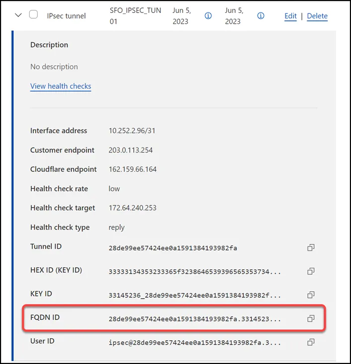
### Static routes
If you refer to the [Environment section](#environment), you will notice there is one subnet within `Trust_L3_Zone`: `10.1.100.0/24`.
Create a [static route](https://developers.cloudflare.com/cloudflare-wan/configuration/manually/how-to/configure-routes/#create-a-static-route) for each of the two IPsec tunnels configured in the previous section, with the following settings (settings not mentioned here can be left with their default settings):
#### Tunnel 01
* **Description**: `SFO_VLAN100_01`
* **Prefix**: `10.1.100.0/24`
* **Tunnel/Next hop**: `SFO_IPSEC_TUN01`
#### Tunnel 02
* **Description**: `SFO_VLAN100_02`
* **Prefix**: `10.1.100.0/24`
* **Tunnel/Next hop**: `SFO_IPSEC_TUN02`

## Palo Alto Networks Next-Generation Firewall
### Tags
While [Tags are optional ↗](https://docs.paloaltonetworks.com/pan-os/9-1/pan-os-admin/policy/use-tags-to-group-and-visually-distinguish-objects/create-and-apply-tags), they can greatly improve object and policy visibility. The following color scheme was implemented in this configuration:
| Tag | Color |
| -------------------- | ------ |
| Trust\_L3\_Zone | Green |
| Untrust\_L3\_Zone | Red |
| Cloudflare\_L3\_Zone | Orange |
Use the Palo Alto Networks Next-Generation Firewall command line to set the tags:
Terminal window
```
set tag Trust_L3_Zone color color2
set tag Untrust_L3_Zone color color1
set tag Cloudflare_L3_Zone color color6
```
### Objects
The use of **Address** and **Address Group** objects wherever possible is strongly encouraged. These objects ensure that configuration elements that reference them are defined accurately and consistently.
Any configuration changes should be applied to the objects and will automatically be applied throughout the remainder of the configuration.
#### Address Objects
Note
Any objects without a netmask specified are `/32`.
| Name | Type | Address | Tags |
| -------------------------------- | ---------- | ---------------- | -------------------- |
| CF\_Health\_Check\_Anycast\_01 | IP Netmask | 172.64.240.253 | Cloudflare\_L3\_Zone |
| CF\_Health\_Check\_Anycast\_02 | IP Netmask | 172.64.240.254 | Cloudflare\_L3\_Zone |
| CF\_Magic\_WAN\_Anycast\_01 | IP Netmask | 162.159.66.164 | Cloudflare\_L3\_Zone |
| CF\_Magic\_WAN\_Anycast\_02 | IP Netmask | 172.64.242.164 | Cloudflare\_L3\_Zone |
| CF\_MWAN\_IPsec\_VTI\_01\_Local | IP Netmask | 10.252.2.27/31 | Cloudflare\_L3\_Zone |
| CF\_MWAN\_IPsec\_VTI\_01\_Remote | IP Netmask | 10.252.2.26 | Cloudflare\_L3\_Zone |
| CF\_MWAN\_IPsec\_VTI\_02\_Local | IP Netmask | 10.252.2.29/31 | Cloudflare\_L3\_Zone |
| CF\_MWAN\_IPsec\_VTI\_02\_Remote | IP Netmask | 10.252.2.28 | Cloudflare\_L3\_Zone |
| CF\_WARP\_Client\_Prefix | IP Netmask | 100.96.0.0/12 | Cloudflare\_L3\_Zone |
| Cloudflare\_IPv4\_01 | IP Netmask | 173.245.48.0/20 | Cloudflare\_L3\_Zone |
| Cloudflare\_IPv4\_02 | IP Netmask | 103.21.244.0/22 | Cloudflare\_L3\_Zone |
| Cloudflare\_IPv4\_03 | IP Netmask | 103.22.200.0/22 | Cloudflare\_L3\_Zone |
| Cloudflare\_IPv4\_04 | IP Netmask | 103.31.4.0/22 | Cloudflare\_L3\_Zone |
| Cloudflare\_IPv4\_05 | IP Netmask | 141.101.64.0/18 | Cloudflare\_L3\_Zone |
| Cloudflare\_IPv4\_06 | IP Netmask | 108.162.192.0/18 | Cloudflare\_L3\_Zone |
| Cloudflare\_IPv4\_07 | IP Netmask | 190.93.240.0/20 | Cloudflare\_L3\_Zone |
| Cloudflare\_IPv4\_08 | IP Netmask | 188.114.96.0/20 | Cloudflare\_L3\_Zone |
| Cloudflare\_IPv4\_09 | IP Netmask | 197.234.240.0/22 | Cloudflare\_L3\_Zone |
| Cloudflare\_IPv4\_10 | IP Netmask | 198.41.128.0/17 | Cloudflare\_L3\_Zone |
| Cloudflare\_IPv4\_11 | IP Netmask | 162.158.0.0/15 | Cloudflare\_L3\_Zone |
| Cloudflare\_IPv4\_12 | IP Netmask | 104.16.0.0/13 | Cloudflare\_L3\_Zone |
| Cloudflare\_IPv4\_13 | IP Netmask | 104.24.0.0/14 | Cloudflare\_L3\_Zone |
| Cloudflare\_IPv4\_14 | IP Netmask | 172.64.0.0/13 | Cloudflare\_L3\_Zone |
| Cloudflare\_IPv4\_15 | IP Netmask | 131.0.72.0/22 | Cloudflare\_L3\_Zone |
| Internet\_L3\_203-0-113-254--24 | IP Netmask | 203.0.113.254/24 | Untrust\_L3\_Zone |
| VLAN0010\_10-1-10-0--24 | IP Netmask | 10.1.10.0/24 | Cloudflare\_L3\_Zone |
| VLAN0020\_10-1-20-0--24 | IP Netmask | 10.1.20.0/24 | Cloudflare\_L3\_Zone |
| VLAN0100\_10-1-100-0--24 | IP Netmask | 10.1.100.0/24 | Trust\_L3\_Zone |
| VLAN0100\_L3\_10-1-100-254--24 | IP Netmask | 10.1.10.254/24 | Trust\_L3\_Zone |
Use the Palo Alto Networks Next-Generation Firewall command line to set the objects:
Terminal window
```
set address CF_Health_Check_Anycast_01 ip-netmask 172.64.240.253
set address CF_Health_Check_Anycast_01 tag Cloudflare_L3_Zone
set address CF_Health_Check_Anycast_02 ip-netmask 172.64.240.254
set address CF_Health_Check_Anycast_02 tag Cloudflare_L3_Zone
set address CF_Magic_WAN_Anycast_01 ip-netmask 162.159.66.164
set address CF_Magic_WAN_Anycast_01 tag Cloudflare_L3_Zone
set address CF_Magic_WAN_Anycast_02 ip-netmask 172.64.242.164
set address CF_Magic_WAN_Anycast_02 tag Cloudflare_L3_Zone
set address CF_MWAN_IPsec_VTI_01_Local ip-netmask 10.252.2.27/31
set address CF_MWAN_IPsec_VTI_01_Local tag Cloudflare_L3_Zone
set address CF_MWAN_IPsec_VTI_02_Local ip-netmask 10.252.2.29/31
set address CF_MWAN_IPsec_VTI_02_Local tag Cloudflare_L3_Zone
set address CF_MWAN_IPsec_VTI_01_Remote ip-netmask 10.252.2.26
set address CF_MWAN_IPsec_VTI_01_Remote tag Cloudflare_L3_Zone
set address CF_MWAN_IPsec_VTI_02_Remote ip-netmask 10.252.2.28
set address CF_MWAN_IPsec_VTI_02_Remote tag Cloudflare_L3_Zone
set address CF_WARP_Client_Prefix ip-netmask 100.96.0.0/12
set address CF_WARP_Client_Prefix tag Cloudflare_L3_Zone
set address Cloudflare_IPv4_01 ip-netmask 173.245.48.0/20
set address Cloudflare_IPv4_01 tag Cloudflare_L3_Zone
set address Cloudflare_IPv4_02 ip-netmask 103.21.244.0/22
set address Cloudflare_IPv4_02 tag Cloudflare_L3_Zone
set address Cloudflare_IPv4_03 ip-netmask 103.22.200.0/22
set address Cloudflare_IPv4_03 tag Cloudflare_L3_Zone
set address Cloudflare_IPv4_04 ip-netmask 103.31.4.0/22
set address Cloudflare_IPv4_04 tag Cloudflare_L3_Zone
set address Cloudflare_IPv4_05 ip-netmask 141.101.64.0/18
set address Cloudflare_IPv4_05 tag Cloudflare_L3_Zone
set address Cloudflare_IPv4_06 ip-netmask 108.162.192.0/18
set address Cloudflare_IPv4_06 tag Cloudflare_L3_Zone
set address Cloudflare_IPv4_07 ip-netmask 190.93.240.0/20
set address Cloudflare_IPv4_07 tag Cloudflare_L3_Zone
set address Cloudflare_IPv4_08 ip-netmask 188.114.96.0/20
set address Cloudflare_IPv4_08 tag Cloudflare_L3_Zone
set address Cloudflare_IPv4_09 ip-netmask 197.234.240.0/22
set address Cloudflare_IPv4_09 tag Cloudflare_L3_Zone
set address Cloudflare_IPv4_10 ip-netmask 198.41.128.0/17
set address Cloudflare_IPv4_10 tag Cloudflare_L3_Zone
set address Cloudflare_IPv4_11 ip-netmask 162.158.0.0/15
set address Cloudflare_IPv4_11 tag Cloudflare_L3_Zone
set address Cloudflare_IPv4_12 ip-netmask 104.16.0.0/13
set address Cloudflare_IPv4_12 tag Cloudflare_L3_Zone
set address Cloudflare_IPv4_13 ip-netmask 104.24.0.0/14
set address Cloudflare_IPv4_13 tag Cloudflare_L3_Zone
set address Cloudflare_IPv4_14 ip-netmask 172.64.0.0/13
set address Cloudflare_IPv4_14 tag Cloudflare_L3_Zone
set address Cloudflare_IPv4_15 ip-netmask 131.0.72.0/22
set address Cloudflare_IPv4_15 tag Cloudflare_L3_Zone
set address Internet_L3_203-0-113-254--24 ip-netmask 203.0.113.254/24
set address Internet_L3_203-0-113-254--24 tag Untrust_L3_Zone
set address VLAN0010_10-1-10-0--24 ip-netmask 10.1.10.0/24
set address VLAN0010_10-1-10-0--24 tag Trust_L3_Zone
set address VLAN0020_10-1-20-0--24 ip-netmask 10.1.20.0/24
set address VLAN0020_10-1-20-0--24 tag Trust_L3_Zone
set address VLAN0100_10-1-100-0--24 ip-netmask 10.1.100.0/24
set address VLAN0100_10-1-100-0--24 tag Trust_L3_Zone
set address VLAN0100_L3_10-1-100-254--24 ip-netmask 10.1.100.254/24
set address VLAN0100_L3_10-1-100-254--24 tag Trust_L3_Zone
```
#### Address Group object
The **Address Group** object used in this configuration provides a single object representation of the entire Cloudflare IPv4 public address space.
| Name | Type | Addresses | Tags |
| ----------------------------- | ------ | -------------------- | -------------------- |
| Cloudflare\_IPv4\_Static\_Grp | Static | Cloudflare\_IPv4\_01 | Cloudflare\_L3\_Zone |
| Cloudflare\_IPv4\_Static\_Grp | Static | Cloudflare\_IPv4\_02 | Cloudflare\_L3\_Zone |
| Cloudflare\_IPv4\_Static\_Grp | Static | Cloudflare\_IPv4\_03 | Cloudflare\_L3\_Zone |
| Cloudflare\_IPv4\_Static\_Grp | Static | Cloudflare\_IPv4\_04 | Cloudflare\_L3\_Zone |
| Cloudflare\_IPv4\_Static\_Grp | Static | Cloudflare\_IPv4\_05 | Cloudflare\_L3\_Zone |
| Cloudflare\_IPv4\_Static\_Grp | Static | Cloudflare\_IPv4\_06 | Cloudflare\_L3\_Zone |
| Cloudflare\_IPv4\_Static\_Grp | Static | Cloudflare\_IPv4\_07 | Cloudflare\_L3\_Zone |
| Cloudflare\_IPv4\_Static\_Grp | Static | Cloudflare\_IPv4\_08 | Cloudflare\_L3\_Zone |
| Cloudflare\_IPv4\_Static\_Grp | Static | Cloudflare\_IPv4\_09 | Cloudflare\_L3\_Zone |
| Cloudflare\_IPv4\_Static\_Grp | Static | Cloudflare\_IPv4\_10 | Cloudflare\_L3\_Zone |
| Cloudflare\_IPv4\_Static\_Grp | Static | Cloudflare\_IPv4\_11 | Cloudflare\_L3\_Zone |
| Cloudflare\_IPv4\_Static\_Grp | Static | Cloudflare\_IPv4\_12 | Cloudflare\_L3\_Zone |
| Cloudflare\_IPv4\_Static\_Grp | Static | Cloudflare\_IPv4\_13 | Cloudflare\_L3\_Zone |
| Cloudflare\_IPv4\_Static\_Grp | Static | Cloudflare\_IPv4\_14 | Cloudflare\_L3\_Zone |
| Cloudflare\_IPv4\_Static\_Grp | Static | Cloudflare\_IPv4\_15 | Cloudflare\_L3\_Zone |
Use the Palo Alto Networks Next-Generation Firewall command line to set the address group object:
Terminal window
```
set address-group Cloudflare_IPv4_Static_Grp static [ Cloudflare_IPv4_01 Cloudflare_IPv4_02 Cloudflare_IPv4_03 Cloudflare_IPv4_04 Cloudflare_IPv4_05 Cloudflare_IPv4_06 Cloudflare_IPv4_07 Cloudflare_IPv4_08 Cloudflare_IPv4_09 Cloudflare_IPv4_10 Cloudflare_IPv4_11 Cloudflare_IPv4_12 Cloudflare_IPv4_13 Cloudflare_IPv4_14 Cloudflare_IPv4_15 ]
set address-group Cloudflare_IPv4_Static_Grp tag Cloudflare_L3_Zone
```
Note
While not covered by this tutorial, it is also possible to use External Dynamic Lists to automatically obtain the most current list of Cloudflare IPv4 addresses by periodically polling [https://www.cloudflare.com/ips-v4 ↗](https://www.cloudflare.com/ips-v4).
### Interface Mgmt - Network Profiles
**Interface Mgmt** profiles control what traffic is allowed _to_ the firewall, as opposed to _through_ the firewall.
Adding an Interface Mgmt profile to the tunnel interfaces will provide the ability to ping the Virtual Tunnel Interface on your firewall(s).
#### Set up via dashboard
You can define an Interface Management Profile to allow ping from the dashboard:
1. Go to **Network Profiles** \> **Interface Mgmt**.
2. In the **Network** tab select **Add**.
3. Create profiles to allow Ping, and in the **Network Services** group select **Ping**.
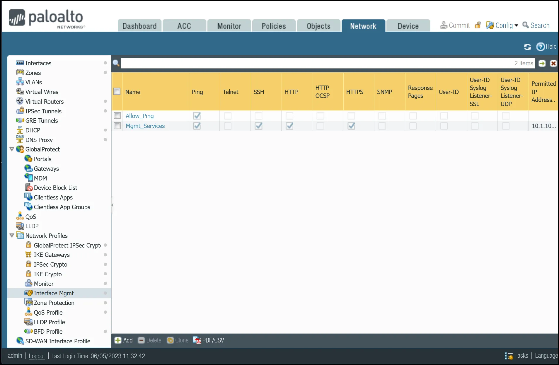 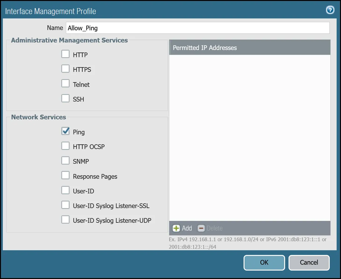
#### Set up via command line
You can also use the command line to allow ping:
Terminal window
```
set network profiles interface-management-profile Allow_Ping userid-service no
set network profiles interface-management-profile Allow_Ping ping yes
```
### Network Interfaces
Palo Alto Networks Next-Generation Firewall (NGFW) is configured with two Ethernet interfaces:
| Interface | Interface Type | IP Address | Virtual Router |
| ----------- | -------------- | ---------------- | -------------- |
| ethernet1/1 | Layer3 | 10.1.100.254/24 | default |
| ethernet1/2 | Layer3 | 203.0.113.254/24 | default |
#### Set up via dashboard
Follow the guidance on the images below to set up the Ethernet interfaces through the dashboard.
##### ethernet1/1: `Trust_L3_Zone`
| Name | Option | Value |
| ---------------- | ---------------------------------------------- | ---------------- |
| **ethernet1/1** | Interface Type | _Layer3_ |
| Netflow Profile | _None_ | |
| **Config tab** | Virtual Router | _default_ |
| Security Zone | _Trust\_L3\_Zone_ | |
| **IPv4 tab** | Type | **Static** |
| IP | VLAN0100\_L3\_10-1-100-254--24 address object | |
| **Advanced tab** | Management Profile | _Mgmt\_Services_ |

##### ethernet1/2: `Untrust_L3_Zone`
| Name | Option | Value |
| ------------------- | ----------------------------------------------- | ------------- |
| **ethernet1/2** | Interface Type | _Layer3_ |
| Netflow Profile | _None_ | |
| **Config tab** | Virtual Router | _default_ |
| Security Zone | _Untrust\_L3\_Zone_ | |
| **IPv4 tab** | Type | **Static** |
| IP | Internet\_L3\_203-0-113-254--24 address object | |
| **Advanced tab** | Management Profile | _Allow\_Ping_ |
| MTU | 576 - 1500 | |
| Adjust TCP MSS | **Enable** | |
| IPv4 MSS Adjustment | 64 | |
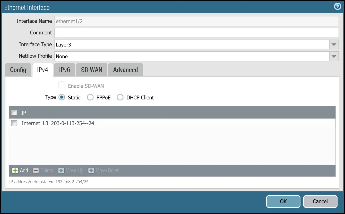
After setting up your Ethernet interfaces, they should show up on the overview page:
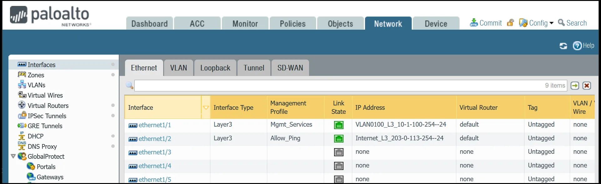
#### Set up via command line
You can also use the command line to set up the Ethernet interfaces.
Terminal window
```
set network interface ethernet ethernet1/1 layer3 ndp-proxy enabled no
set network interface ethernet ethernet1/1 layer3 lldp enable no
set network interface ethernet ethernet1/1 layer3 ip VLAN0100_L3_10-1-100-254--24
set network interface ethernet ethernet1/1 layer3 interface-management-profile Mgmt_Services
set network interface ethernet ethernet1/2 layer3 ndp-proxy enabled no
set network interface ethernet ethernet1/2 layer3 lldp enable no
set network interface ethernet ethernet1/2 layer3 ip Internet_L3_203-0-113-254--24
set network interface ethernet ethernet1/2 layer3 interface-management-profile Allow_Ping
set network interface ethernet ethernet1/2 layer3 adjust-tcp-mss enable yes
set network interface ethernet ethernet1/2 layer3 adjust-tcp-mss ipv4-mss-adjustment 64
```
### Tunnel interfaces
Establishing IPsec tunnels to Cloudflare WAN requires two tunnel interfaces - one to each of the two Cloudflare anycast IP addresses. You also have to ensure that `Allow_Ping` is bound to both tunnel adapters in **Advanced** \> **Management Profile**.
Review the images below for more information.
Note
MTU is set to `1450`. This value may need to be adjusted for optimal performance on your network.
#### Set up via dashboard
##### tunnel.1 - `Cloudflare_L3_Zone`
| Name | Option | Value |
| ---------------- | ---------------------- | ----------------------------------------------- |
| **tunnel.1** | Netflow Profile | _None_ |
| **Config tab** | Virtual Router | _default_ |
| Security Zone | _Cloudflare\_L3\_Zone_ | |
| **IPv4 tab** | IP | CF\_MWAN\_IPsec\_VTI\_01\_Local address object |
| **Advanced tab** | Management Profile | _Allow\_Ping_ |
| MTU | 1450 | |
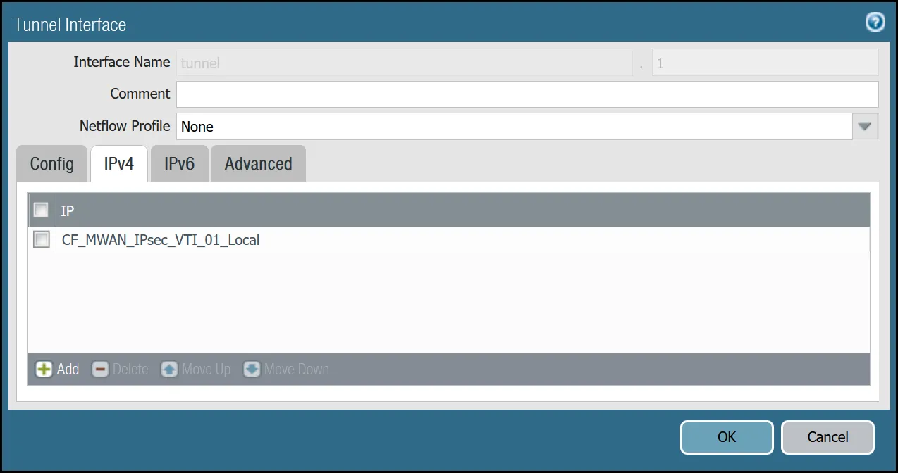
_Note: Labels in these images may reflect previous product names._
##### tunnel.2 - `Cloudflare_L3_Zone`
| Name | Option | Value |
| ---------------- | ---------------------- | ----------------------------------------------- |
| **tunnel.2** | Netflow Profile | _None_ |
| **Config tab** | Virtual Router | _default_ |
| Security Zone | _Cloudflare\_L3\_Zone_ | |
| **IPv4 tab** | IP | CF\_MWAN\_IPsec\_VTI\_02\_Local address object |
| **Advanced tab** | Management Profile | _Allow\_Ping_ |
| MTU | 1450 | |
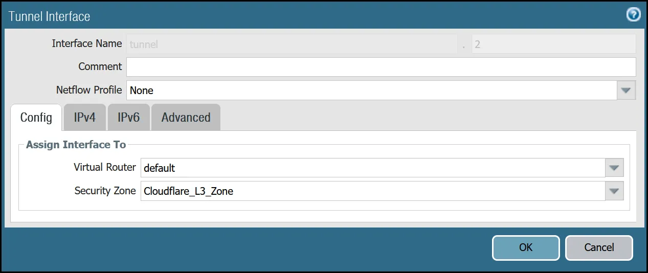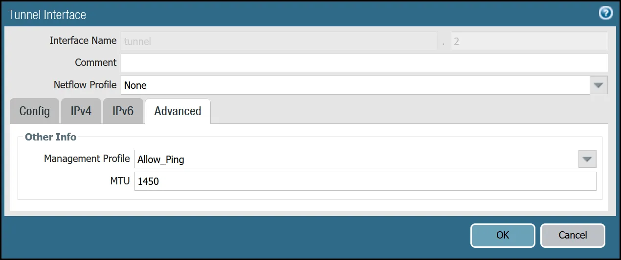
_Note: Labels in these images may reflect previous product names._
After setting up your Tunnel interfaces, they should show up on the overview page:
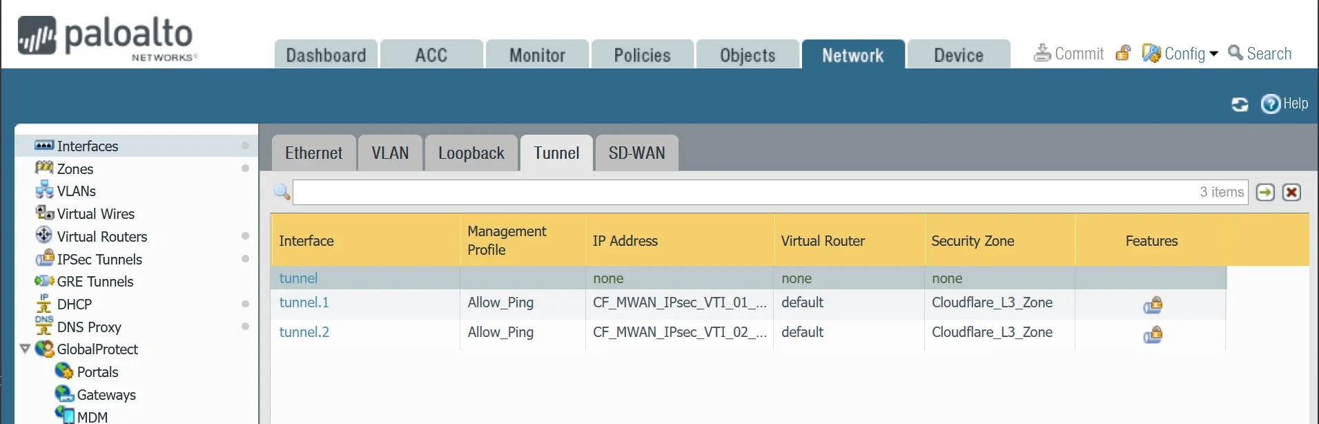
_Note: Labels in this image may reflect previous product names._
#### Set up via command line
You can also set up your tunnels in the command line:
Terminal window
```
set network interface tunnel units tunnel.1 ip CF_MWAN_IPsec_VTI_01_Local
set network interface tunnel units tunnel.1 mtu 1450
set network interface tunnel units tunnel.1 interface-management-profile Allow_Ping
set network interface tunnel units tunnel.2 ip CF_MWAN_IPsec_VTI_02_Local
set network interface tunnel units tunnel.2 mtu 1450
set network interface tunnel units tunnel.2 interface-management-profile Allow_Ping
```
### Zones
The Palo Alto Networks Next-Generation Firewall (NGFW) used to create this tutorial includes the following zones and corresponding network interfaces:
| Zone | Interface | Interface |
| -------------------- | ----------- | --------- |
| Trust\_L3\_Zone | ethernet1/1 | |
| Untrust\_L3\_Zone | ethernet1/2 | |
| Cloudflare\_L3\_Zone | tunnel.1 | tunnel.2 |
The tunnel interfaces are placed in a separate zone to facilitate the configuration of more granular security policies. The use of any other zone for the tunnel interfaces will require adapting the configuration accordingly.
Note
Any Cloudflare WAN protected networks that are not local should be considered part of the `Cloudflare_L3_Zone`.
#### Set up via dashboard
##### `Trust_L3_zone`
| Name | Option | Value |
| ----------------------- | --------------- | ------ |
| Trust\_L3\_zone | Log setting | _None_ |
| Type | _Layer3_ | |
| Interfaces | **ethernet1/1** | |
| Zone Protection Profile | _None_ | |
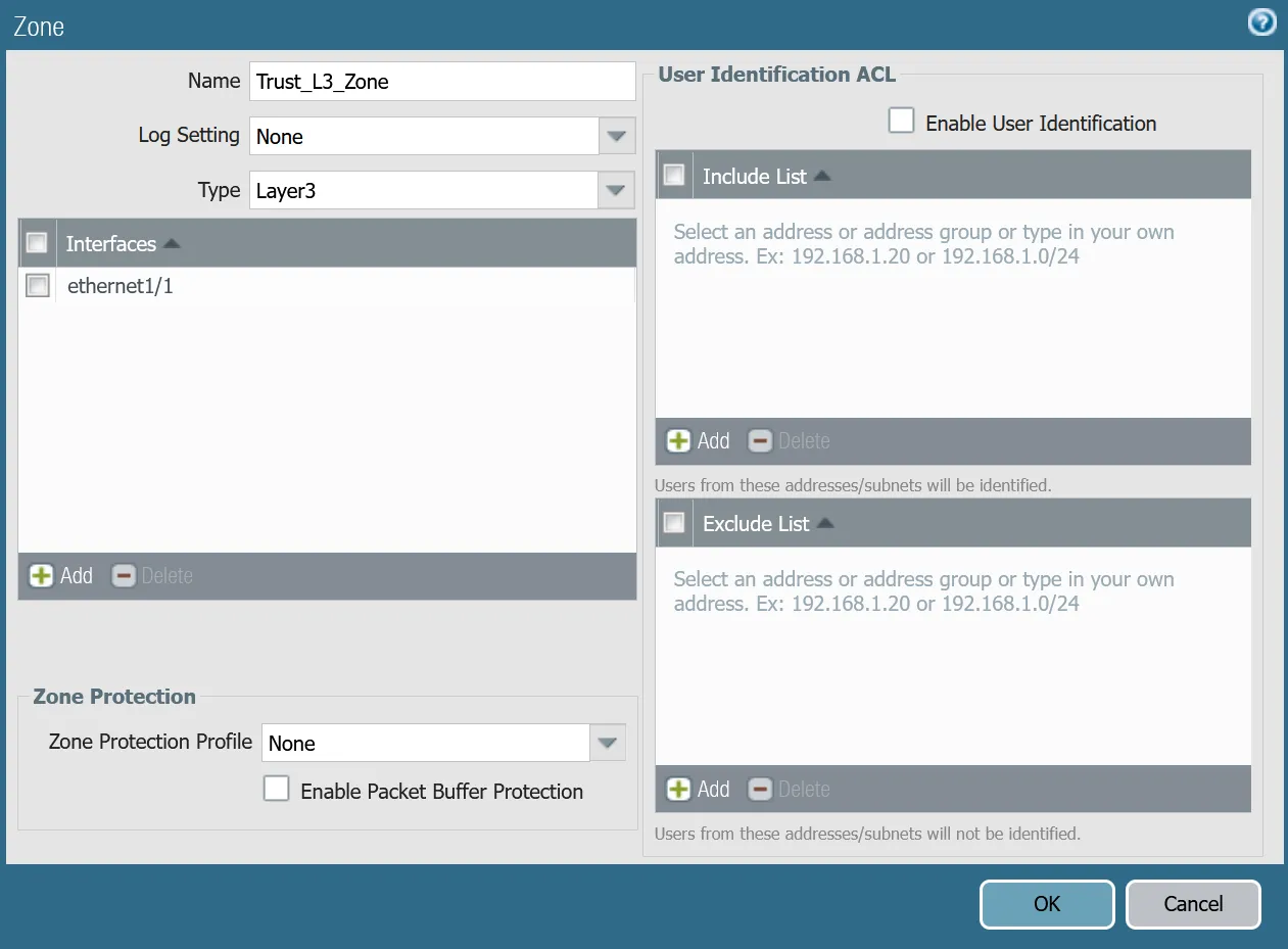
##### `Untrust_L3_zone`
| Name | Option | Value |
| ----------------------- | --------------------- | ------ |
| Untrust\_L3\_zone | Log setting | _None_ |
| Type | _Layer3_ | |
| Interfaces | **ethernet1/2** | |
| Zone Protection Profile | _Untrust\_Zone\_Prof_ | |
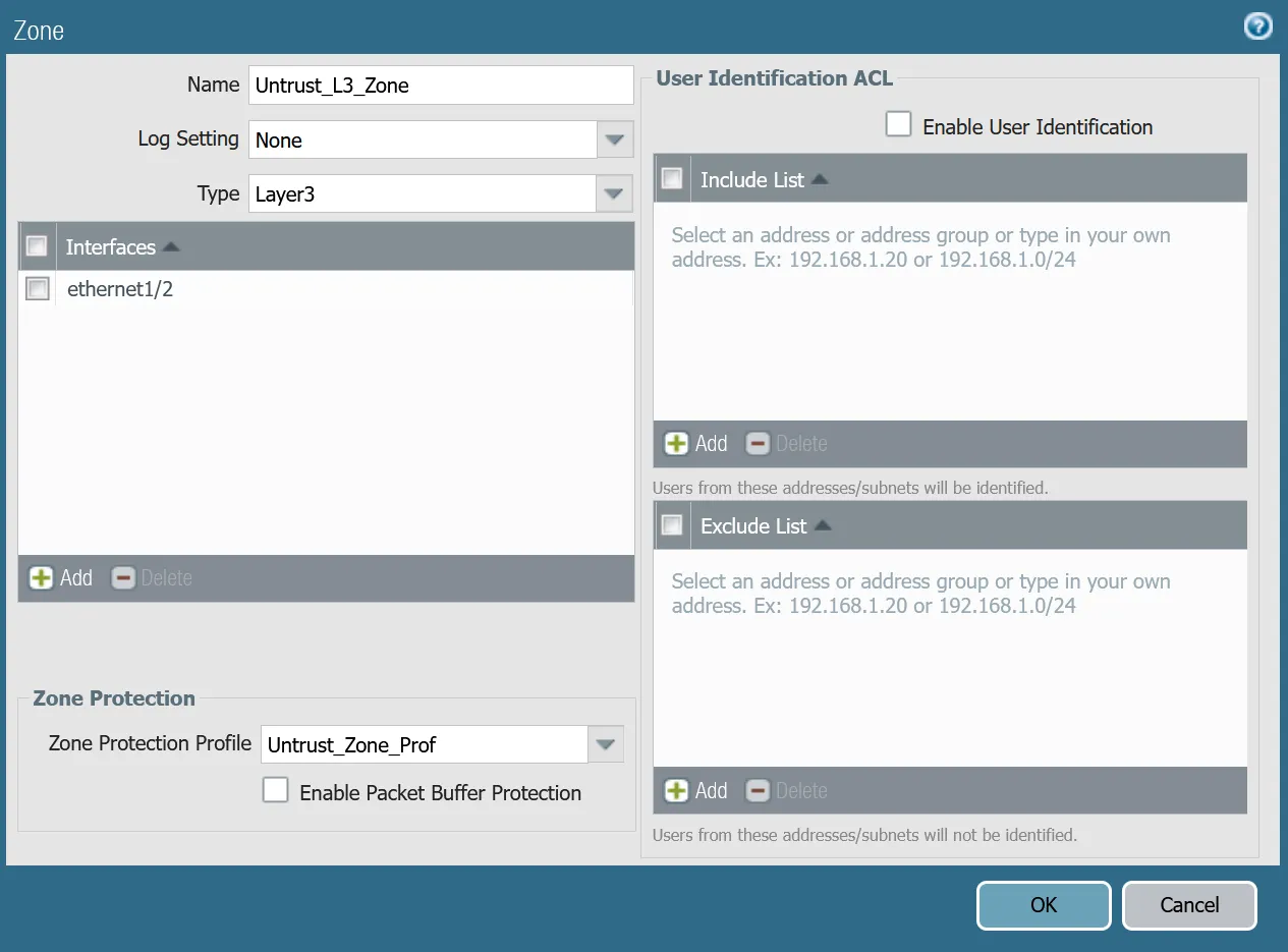
##### `Cloudflare_L3_zone`
| Name | Option | Value |
| ----------------------- | ------------------------- | ------ |
| Cloudflare\_L3\_zone | Log setting | _None_ |
| Type | _Layer3_ | |
| Interfaces | **tunnel.1** **tunnel.2** | |
| Zone Protection Profile | _None_ | |
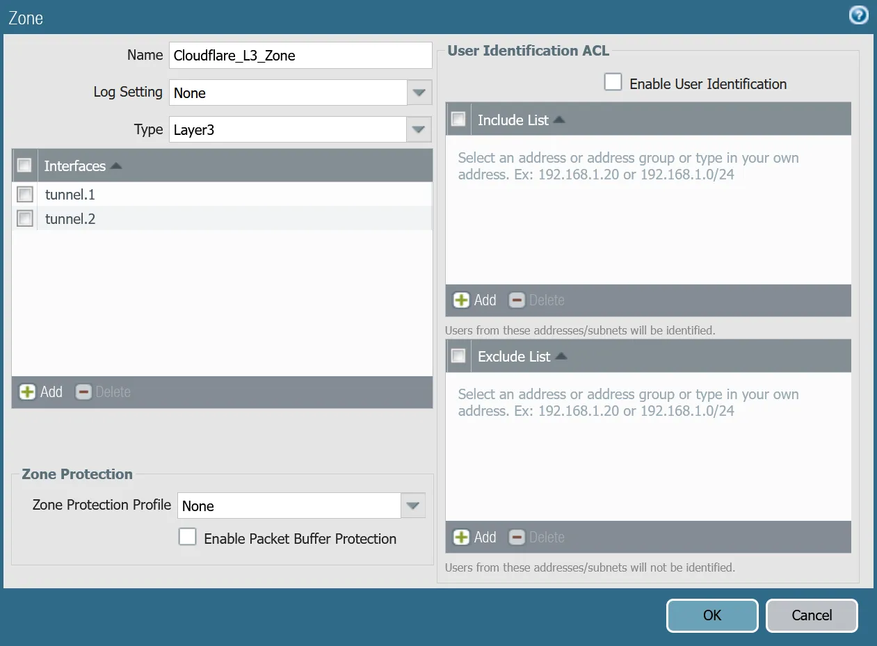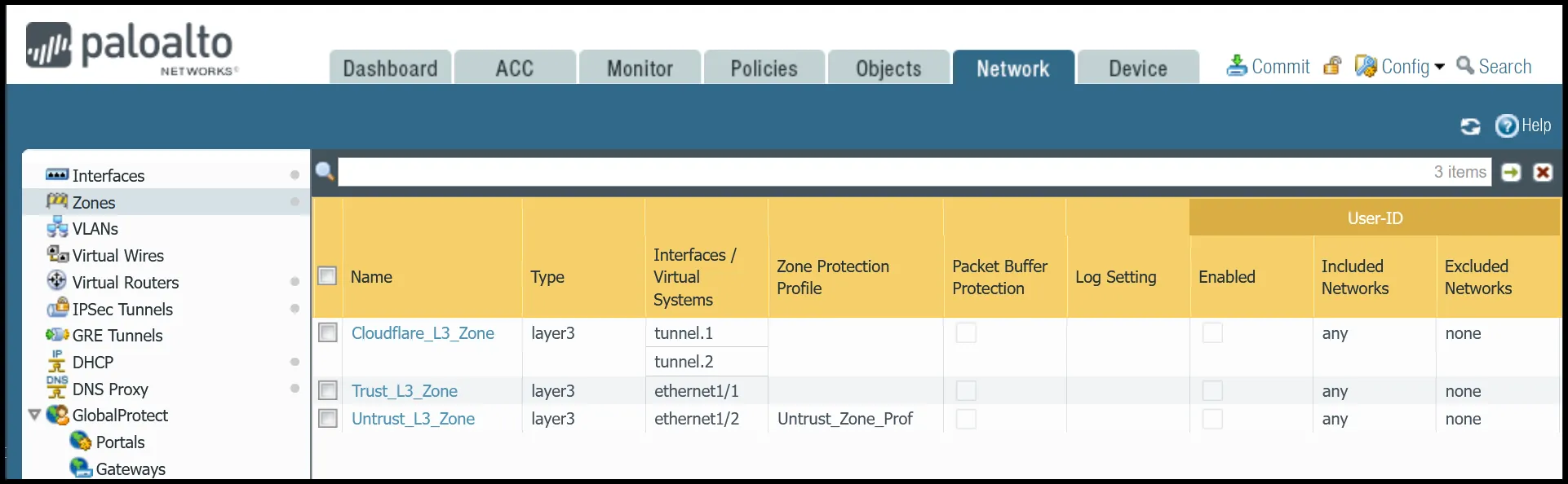
#### Set up via command line
You can also use the command line to associate zones and interfaces:
Terminal window
```
set zone Trust_L3_Zone network layer3 ethernet1/1
set zone Untrust_L3_Zone network layer3 ethernet1/2
set zone Cloudflare_L3_Zone network layer3 [ tunnel.1 tunnel.2 ]
```
### Apply Changes
This would be a good time to save and commit the configuration changes made so far. Once complete, make sure you test basic connectivity to and from the firewall.
### IKE crypto profile Phase 1
Add a new IKE crypto profile to support the required parameters for Phase 1.
Multiple DH groups and authentication settings are defined in the desired order. Palo Alto Networks Next-Generation Firewall (NGFW) will automatically negotiate the optimal settings based on specified values.
#### Set up via dashboard
| Name | Option | Value |
| ----------------------------- | -------------------------------- | ----------- |
| CF\_IKE\_Crypto\_CBC | DH Group | **group20** |
| Authentication | **sha512** **sha384** **sha256** | |
| Encryption | **aes-256-cbc** | |
| Key Lifetime | 24 hours | |
| IKEv2 Authentication Multiple | 0 | |
#### Set up via command line
You can also set up the crypto profile for Phase 1 via the command line:
Terminal window
```
set network ike crypto-profiles ike-crypto-profiles CF_IKE_Crypto_CBC hash [ sha512 sha384 sha256 ]
set network ike crypto-profiles ike-crypto-profiles CF_IKE_Crypto_CBC dh-group [ group20 ]
set network ike crypto-profiles ike-crypto-profiles CF_IKE_Crypto_CBC encryption aes-256-cbc
set network ike crypto-profiles ike-crypto-profiles CF_IKE_Crypto_CBC lifetime hours 24
set network ike crypto-profiles ike-crypto-profiles CF_IKE_Crypto_CBC authentication-multiple 0
```
### IPsec crypto profile Phase 2
Add a new IPsec crypto profile to support the required parameters for Phase 2.
Multiple Authentication settings are defined in the desired order. Palo Alto Networks Next-Generation Firewall (NGFW) will automatically negotiate the optimal settings based on specified values.
#### Set up via dashboard
| Name | Option | Value |
| ---------------------- | ------------------- | --------------- |
| CF\_IPsec\_Crypto\_CBC | Encryption | **aes-256-cbc** |
| Authentication | **sha256** **sha1** | |
| DH Group | **group20** | |
| Lifetime | 8 hours | |
#### Set up via command line
You can also set up the IPsec crypto profile for Phase 2 via the command line:
Terminal window
```
set network ike crypto-profiles ipsec-crypto-profiles CF_IPsec_Crypto_CBC esp authentication [ sha256 sha1 ]
set network ike crypto-profiles ipsec-crypto-profiles CF_IPsec_Crypto_CBC esp encryption aes-256-cbc
set network ike crypto-profiles ipsec-crypto-profiles CF_IPsec_Crypto_CBC lifetime hours 8
set network ike crypto-profiles ipsec-crypto-profiles CF_IPsec_Crypto_CBC dh-group group20
```
### IKE Gateways
Note
Any other settings not specified should be left at their default values. Any deviation may lead to undesirable behavior and are not supported.
Define two IKE Gateways to establish the two IPsec tunnels to Cloudflare. Make sure to define the following values:
#### Set up via dashboard
##### Tunnel 1 settings: `CF_Magic_WAN_IKE_01`
Note
Make sure you select `CF_IKE_Crypto_CBC` as the IKE Crypto profile.
| Tab | Option | Value |
| -------------------- | ----------------------------------------------------------------------------------------------------------------------------------------------------------------------------------------------------------------------- | ----------------------- |
| **General tab** | Name | CF\_Magic\_WAN\_IKE\_01 |
| Version | _IKEv2 only mode_. Make sure both IKE Gateways are based only on this setting. | |
| Local IP Address | Internet\_L3\_203-0-113-254--24 | |
| Peer address | CF\_Magic\_WAN\_Anycast\_01 | |
| Pre-Shared Key | This value can be obtained from the Cloudflare dashboard - value is unique per tunnel. | |
| Local Identification | _FQDN (hostname)_. You can obtain this value from the Cloudflare Dashboard - value is unique per tunnel. | |
| Peer Identification | _None_ | |
| **Advanced tab** | IKE Crypto Profile | _CF\_IKE\_Crypto\_CBC_ |
| Liveness Check | The default value (five seconds) is sufficient. This setting is used to periodically determine if there are any underlying connectivity issues that may adversely affect the creation of Phase 1 Security Associations. | |

_Note: Labels in these images may reflect previous product names._
##### Tunnel 2 settings: `CF_Magic_WAN_IKE_02`
Note
Make sure you select `CF_IKE_Crypto_CBC` as the IKE Crypto profile.
| Tab | Option | Value |
| -------------------- | ----------------------------------------------------------------------------------------------------------------------------------------------------------------------------------------------------------------------- | ----------------------- |
| **General tab** | Name | CF\_Magic\_WAN\_IKE\_02 |
| Version | _IKEv2 only mode_. Make sure both IKE Gateways are based only on this setting. | |
| Local IP Address | Internet\_L3\_203-0-113-254--24 | |
| Peer address | CF\_Magic\_WAN\_Anycast\_02 | |
| Pre-Shared Key | This value can be obtained from the Cloudflare dashboard - value is unique per tunnel. | |
| Local Identification | _FQDN (hostname)_. You can obtain this value from the Cloudflare Dashboard - value is unique per tunnel. | |
| Peer Identification | _None_ | |
| **Advanced tab** | IKE crypto profile | _CF\_IKE\_Crypto\_CBC_ |
| Liveness Check | The default value (five seconds) is sufficient. This setting is used to periodically determine if there are any underlying connectivity issues that may adversely affect the creation of Phase 1 Security Associations. | |
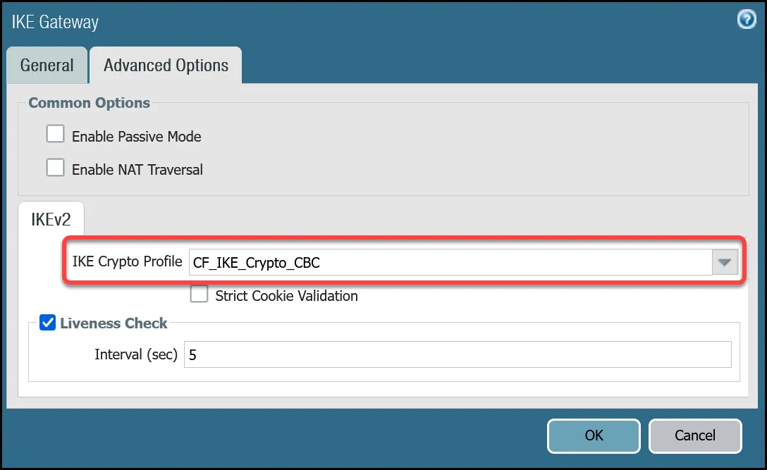
_Note: Labels in these images may reflect previous product names._
#### Set up via command line
##### Tunnel 1 settings: `CF_Magic_WAN_IKE_01`
Terminal window
```
set network ike gateway CF_Magic_WAN_IKE_01 protocol ikev1 dpd enable yes
set network ike gateway CF_Magic_WAN_IKE_01 protocol ikev2 dpd enable yes
set network ike gateway CF_Magic_WAN_IKE_01 protocol ikev2 ike-crypto-profile CF_IKE_Crypto_CBC
set network ike gateway CF_Magic_WAN_IKE_01 protocol version ikev2
set network ike gateway CF_Magic_WAN_IKE_01 local-address ip Internet_L3_203-0-113-254--24
set network ike gateway CF_Magic_WAN_IKE_01 local-address interface ethernet1/2
set network ike gateway CF_Magic_WAN_IKE_01 protocol-common nat-traversal enable no
set network ike gateway CF_Magic_WAN_IKE_01 protocol-common fragmentation enable no
set network ike gateway CF_Magic_WAN_IKE_01 peer-address ip CF_Magic_WAN_Anycast_01
set network ike gateway CF_Magic_WAN_IKE_01 authentication pre-shared-key key -AQ==Xdcd9ir5o5xhjuIH---------------------HsRoVf+M0TTG4ja3EzulN37zMOwGs
set network ike gateway CF_Magic_WAN_IKE_01 local-id id 28de99ee57424ee0a1591384193982fa.33145236.ipsec.cloudflare.com
set network ike gateway CF_Magic_WAN_IKE_01 local-id type fqdn
set network ike gateway CF_Magic_WAN_IKE_01 disabled no
```
##### Tunnel 2 settings: `CF_Magic_WAN_IKE_02`
Terminal window
```
set network ike gateway CF_Magic_WAN_IKE_02 protocol ikev1 dpd enable yes
set network ike gateway CF_Magic_WAN_IKE_02 protocol ikev2 dpd enable yes
set network ike gateway CF_Magic_WAN_IKE_02 protocol ikev2 ike-crypto-profile CF_IKE_Crypto_CBC
set network ike gateway CF_Magic_WAN_IKE_02 protocol version ikev2
set network ike gateway CF_Magic_WAN_IKE_02 local-address ip Internet_L3_203-0-113-254--24
set network ike gateway CF_Magic_WAN_IKE_02 local-address interface ethernet1/2
set network ike gateway CF_Magic_WAN_IKE_02 protocol-common nat-traversal enable no
set network ike gateway CF_Magic_WAN_IKE_02 protocol-common fragmentation enable no
set network ike gateway CF_Magic_WAN_IKE_02 peer-address ip CF_Magic_WAN_Anycast_02
set network ike gateway CF_Magic_WAN_IKE_02 authentication pre-shared-key key -AQ==rvwEulxx7wLBl---------------------swSeJPXxxM2cfPbt7q4HZZGZZ8
set network ike gateway CF_Magic_WAN_IKE_02 local-id id b87322b0915b47158667bf1653990e66.33145236.ipsec.cloudflare.com
set network ike gateway CF_Magic_WAN_IKE_02 local-id type fqdn
set network ike gateway CF_Magic_WAN_IKE_02 disabled no
```
### IPsec Tunnels
With the IKE Gateways defined, the next step is to configure two IPsec Tunnels - one corresponding to each of the two IKE Gateways configured in the previous section.
#### Prerequisites
There are a few prerequisites you should be aware of before continuing:
* Do not configure Proxy IDs. Cloudflare WAN IPsec tunnels are based on the route-based VPN model. Proxy IDs are used with policy-based VPNs.
* Disable Replay Protection, under the Advanced Options.
* Disable Tunnel Monitor. It can cause undesirable results. Tunnel Monitor is a Palo Alto Networks proprietary feature that assumes there are Palo Alto Networks Next-Generation Firewall devices on both sides of the IPsec tunnel. Also, Tunnel Monitor is intended for use with IPsec tunnels based on IKEv1 (Cloudflare WAN IPsec tunnels are based on IKEv2).
#### Set up via dashboard
##### Tunnel 1 settings: `CF_Magic_WAN_IPsec_01`
| Name | Option | Value |
| ------------------------- | ------------------------- | -------- |
| CF\_Magic\_WAN\_IPsec\_01 | Tunnel interface | tunnel.1 |
| IKE Gateway | _CF\_Magic\_WAN\_IKE\_01_ | |
| IPsec crypto profile | _CF\_IKE\_Crypto\_CBC_ | |
| Enable Replay Protection | **Disable** | |
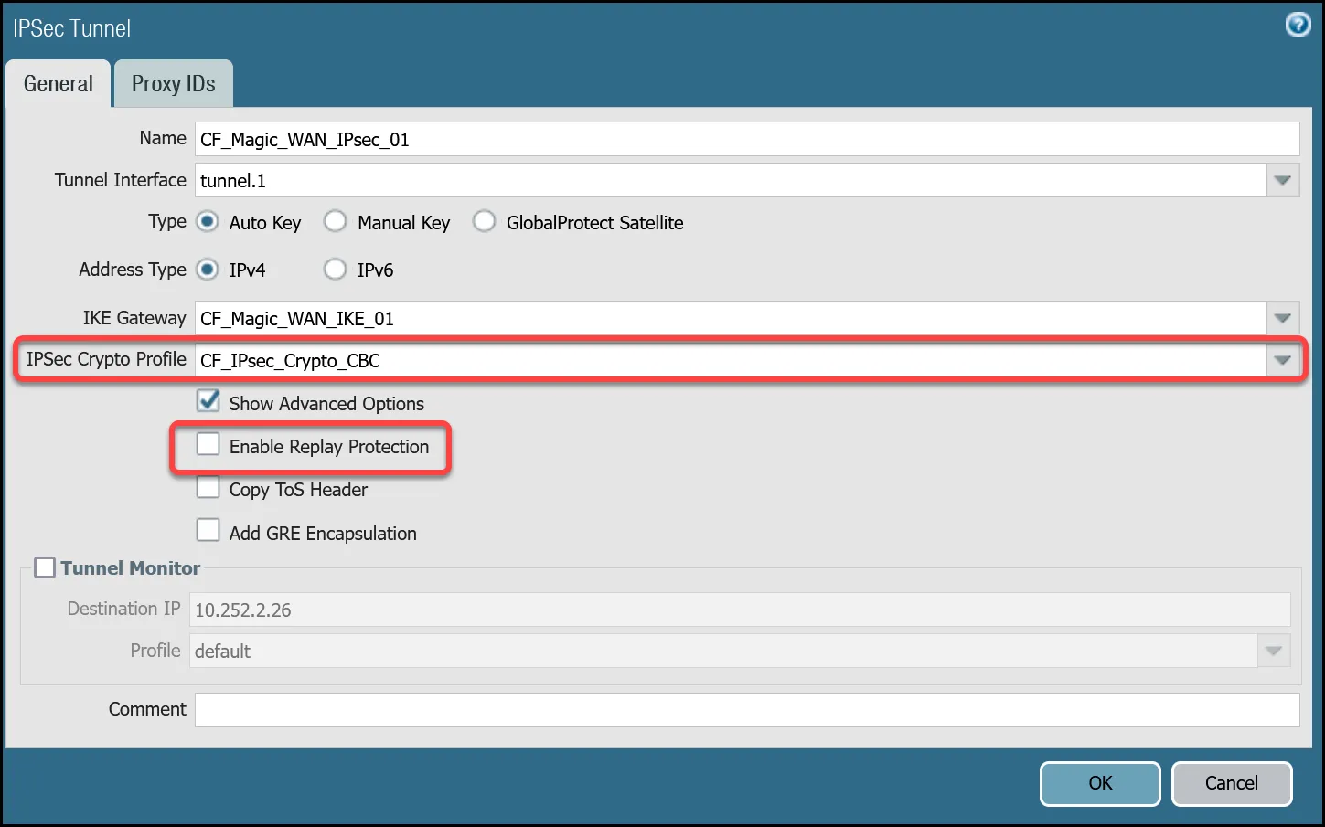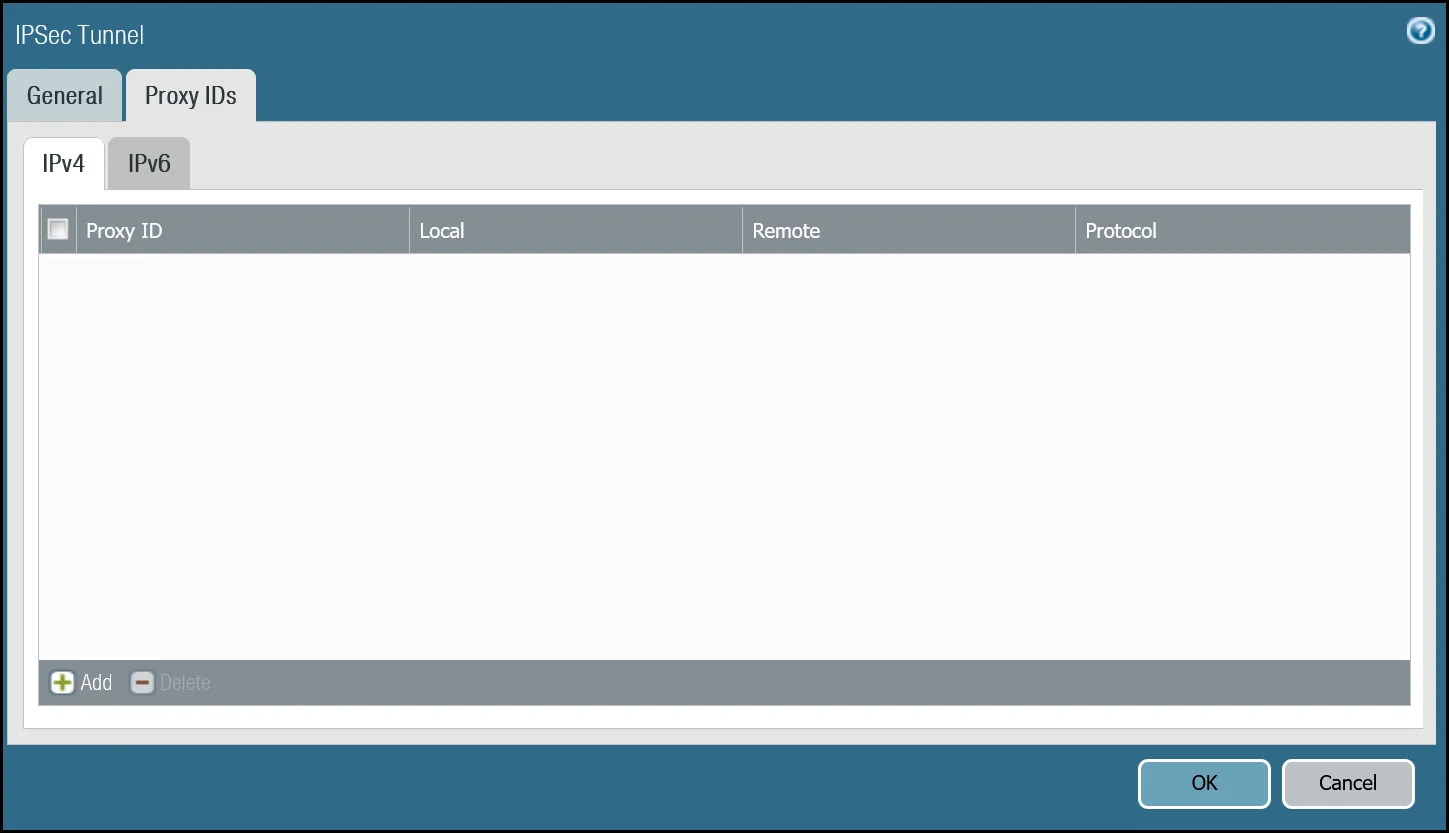
_Note: Labels in these images may reflect previous product names._
##### Tunnel 2 settings: `CF_Magic_WAN_IPsec_02`
| Name | Option | Value |
| ------------------------- | ------------------------- | -------- |
| CF\_Magic\_WAN\_IPsec\_02 | Tunnel interface | tunnel.2 |
| IKE Gateway | _CF\_Magic\_WAN\_IKE\_02_ | |
| IPsec crypto profile | _CF\_IKE\_Crypto\_CBC_ | |
| Enable Replay Protection | **Disable** | |
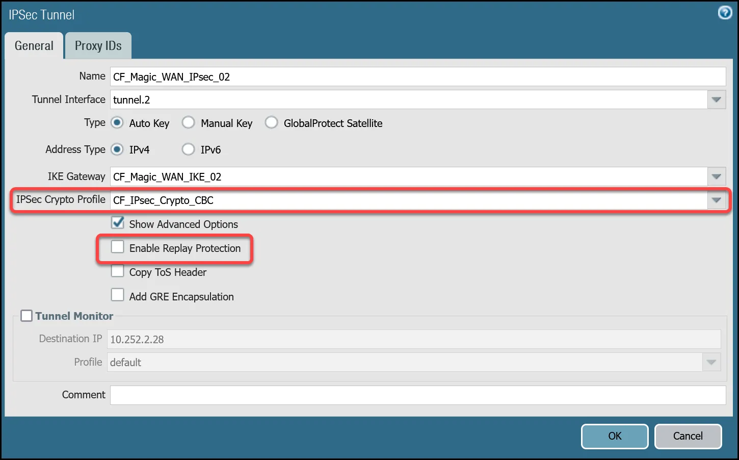
_Note: Labels in these images may reflect previous product names._
#### Set up via command line
##### Tunnel 1 settings: `CF_Magic_WAN_IPsec_01`
Terminal window
```
set network tunnel ipsec CF_Magic_WAN_IPsec_01 auto-key ike-gateway CF_Magic_WAN_IKE_01
set network tunnel ipsec CF_Magic_WAN_IPsec_01 auto-key ipsec-crypto-profile CF_IPsec_Crypto_CBC
set network tunnel ipsec CF_Magic_WAN_IPsec_01 tunnel-monitor destination-ip 10.252.2.26
set network tunnel ipsec CF_Magic_WAN_IPsec_01 tunnel-monitor tunnel-monitor-profile default
set network tunnel ipsec CF_Magic_WAN_IPsec_01 tunnel-interface tunnel.1
set network tunnel ipsec CF_Magic_WAN_IPsec_01 anti-replay no
set network tunnel ipsec CF_Magic_WAN_IPsec_01 disabled no
```
##### Tunnel 2 settings: `CF_Magic_WAN_IPsec_02`
Terminal window
```
set network tunnel ipsec CF_Magic_WAN_IPsec_02 auto-key ike-gateway CF_Magic_WAN_IKE_02
set network tunnel ipsec CF_Magic_WAN_IPsec_02 auto-key ipsec-crypto-profile CF_IPsec_Crypto_CBC
set network tunnel ipsec CF_Magic_WAN_IPsec_02 tunnel-monitor destination-ip 10.252.2.28
set network tunnel ipsec CF_Magic_WAN_IPsec_02 tunnel-monitor tunnel-monitor-profile default
set network tunnel ipsec CF_Magic_WAN_IPsec_02 tunnel-interface tunnel.2
set network tunnel ipsec CF_Magic_WAN_IPsec_02 anti-replay no
set network tunnel ipsec CF_Magic_WAN_IPsec_02 disabled no
```
### Apply Changes
This would be a good time to save and commit the configuration changes made thus far. Once complete, make sure you test basic connectivity across the IPsec tunnels.
### IPsec tunnel connectivity tests
This is a good time to ensure the IPsec tunnels are established and to validate basic connectivity.
Note
Tunnel health checks will not function until security policies and policy-based forwarding are configured. This series of tests is focused on testing IPsec connectivity exclusively.
#### Verify IKE Phase 1 Communications
The first step is to verify IKE Phase 1 completed successfully:
##### Syntax
Terminal window
```
show vpn ike-sa gateway [value]
```
##### Example for `CF_Magic_WAN_IKE_01`
Terminal window
```
admin@panvm03> show vpn ike-sa gateway CF_Magic_WAN_IKE_01
There is no IKEv1 phase-1 SA found.
There is no IKEv1 phase-2 SA found.
IKEv2 SAs
Gateway ID Peer-Address Gateway Name Role SN Algorithm Established Expiration Xt Child ST
---------- ------------ ------------ ---- -- --------- ----------- ---------- -- ----- --
2 162.159.66.164 CF_Magic_WAN_IKE_01 Init 67 PSK/DH20/A256/SHA256 Jun.04 21:09:13 Jun.05 05:09:13 0 1 Established
IKEv2 IPsec Child SAs
Gateway Name TnID Tunnel ID Parent Role SPI(in) SPI(out) MsgID ST
------------ ---- ------ -- ------ ---- ------- -------- ----- --
CF_Magic_WAN_IKE_01 2 CF_Magic_WAN_IPsec_01 322550 67 Init FCAEE176 1EF41BA9 000007B4 Mature
Show IKEv2 SA: Total 2 gateways found. 1 ike sa found.
```
##### Example for `CF_Magic_WAN_IKE_02`
Terminal window
```
admin@panvm03> show vpn ike-sa gateway CF_Magic_WAN_IKE_02
There is no IKEv1 phase-1 SA found.
There is no IKEv1 phase-2 SA found.
IKEv2 SAs
Gateway ID Peer-Address Gateway Name Role SN Algorithm Established Expiration Xt Child ST
---------- ------------ ------------ ---- -- --------- ----------- ---------- -- ----- --
3 172.64.242.164 CF_Magic_WAN_IKE_02 Init 66 PSK/DH20/A256/SHA256 Jun.04 20:37:42 Jun.05 04:37:42 0 2 Established
IKEv2 IPsec Child SAs
Gateway Name TnID Tunnel ID Parent Role SPI(in) SPI(out) MsgID ST
------------ ---- ------ -- ------ ---- ------- -------- ----- --
CF_Magic_WAN_IKE_02 3 CF_Magic_WAN_IPsec_02 323145 66 Init B6EDA356 43F71BC5 00000A52 Mature
Show IKEv2 SA: Total 2 gateways found. 1 ike sa found.
```
#### Troubleshooting IKE Phase 1 Communications
Cloudflare WAN IPsec tunnels expect the customer device will initiate the IPsec tunnels. The tunnels may not establish if there is no traffic that would traverse the tunnel under normal conditions. In this case, it may be necessary to force IKE Phase 1.
##### Syntax
Terminal window
```
test vpn ike-sa gateway [value]
```
##### Example for `CF_Magic_WAN_IKE_01`
Terminal window
```
admin@panvm03> test vpn ike-sa gateway CF_Magic_WAN_IKE_01
Start time: Jun.05 00:30:29
Initiate 1 IKE SA.
```
##### Example for `CF_Magic_WAN_IKE_02`
Terminal window
```
admin@panvm03> test vpn ike-sa gateway CF_Magic_WAN_IKE_02
Start time: Jun.05 00:30:33
Initiate 1 IKE SA.
```
Repeat these commands for the respective tunnel to ensure the IKE SA(s) display as expected.
#### Verify IPsec Phase 2 Communications
To ensure the IPsec tunnels are established, ping the remote Virtual Tunnel Interface (Cloudflare side) from the command line on the Palo Alto Networks Next-Generation Firewall. Ensure you specify the source IP address of the ping from the local side of the Virtual Tunnel Interface:
##### Syntax
Terminal window
```
show vpn ipsec-sa tunnel [value]
```
##### Example for `CF_Magic_WAN_IPsec_01`
Terminal window
```
admin@panvm03> show vpn ipsec-sa tunnel CF_Magic_WAN_IPsec_01
GwID/client IP TnID Peer-Address Tunnel(Gateway) Algorithm SPI(in) SPI(out) life(Sec/KB) remain-time(Sec)
-------------- ---- ------------ --------------- --------- ------- -------- ------------ ----------------
2 2 162.159.66.164 CF_Magic_WAN_IPsec_01(CF_Magic_WAN_IKE_01) ESP/A256/SHA256 B5D09AB8 9FA69407 3600/Unlimited 3445
Show IPsec SA: Total 1 tunnels found. 1 ipsec sa found.
```
##### Example for `CF_Magic_WAN_IPsec_02`
Terminal window
```
admin@panvm03> show vpn ipsec-sa tunnel CF_Magic_WAN_IPsec_02
GwID/client IP TnID Peer-Address Tunnel(Gateway) Algorithm SPI(in) SPI(out) life(Sec/KB) remain-time(Sec)
-------------- ---- ------------ --------------- --------- ------- -------- ------------ ----------------
3 3 172.64.242.164 CF_Magic_WAN_IPsec_02(CF_Magic_WAN_IKE_02) ESP/A256/SHA256 CAEA6F09 EC6ACC7A 3600/Unlimited 3361
Show IPsec SA: Total 1 tunnels found. 1 ipsec sa found.
```
#### Troubleshooting IPsec Phase 2 Communications
Cloudflare WAN IPsec tunnels expect the customer device will initiate the IPsec tunnels. The tunnels may not establish if there is no traffic that would traverse the tunnel under normal conditions. In this case, it may be necessary to force IPsec Phase 2\. This is typically unnecessary as once IKE Phase 1 negotiates successfully, IPsec Phase 2 automatically establishes the tunnel. The test is still worth performing.
##### Syntax
Terminal window
```
test vpn ipsec-sa tunnel [value]
```
##### Example for `CF_Magic_WAN_IPsec_01`
Terminal window
```
admin@panvm03> test vpn ipsec-sa tunnel CF_Magic_WAN_IPsec_01
Start time: Jun.05 00:37:50
Initiate 1 IPsec SA for tunnel CF_Magic_WAN_IPsec_01.
```
##### Example for `CF_Magic_WAN_IPsec_02`
Terminal window
```
admin@panvm03> test vpn ipsec-sa tunnel CF_Magic_WAN_IPsec_02
Start time: Jun.05 00:38:52
Initiate 1 IPsec SA for tunnel CF_Magic_WAN_IPsec_02.
```
Repeat these commands for the respective tunnel to ensure the IPsec SA(s) display as expected.
#### Ping Remote Virtual Tunnel interfaces
Use ping to source traffic from the IP address of the Virtual Tunnel interface on Palo Alto Networks Next-Generation Firewall (NGFW) to the IP address of the Virtual Tunnel Interface on the Cloudflare side of the IPsec tunnel.
Note
The interface address is defined with a `/31` netmask. There have been isolated cases where NGFW exhibited issues when using ping to verify connectivity between the local and remote Virtual Tunnel interfaces. This behavior can vary depending on the version of PAN-OS installed on the firewall. If you encounter this issue, either switch to a `/30` netmask, or contact Palo Alto Networks support for assistance.
##### Syntax
Terminal window
```
ping source [value src IP] host [value dst IP]
```
##### Example for Tunnel 1
Terminal window
```
admin@panvm03> ping source 10.252.2.27 host 10.252.2.26
PING 10.252.2.26 (10.252.2.26) from 10.252.2.27 : 56(84) bytes of data.
64 bytes from 10.252.2.26: icmp_seq=1 ttl=64 time=2.71 ms
64 bytes from 10.252.2.26: icmp_seq=2 ttl=64 time=2.03 ms
64 bytes from 10.252.2.26: icmp_seq=3 ttl=64 time=1.98 ms
64 bytes from 10.252.2.26: icmp_seq=4 ttl=64 time=1.98 ms
^C
--- 10.252.2.26 ping statistics ---
4 packets transmitted, 4 received, 0% packet loss, time 3002ms
rtt min/avg/max/mdev = 1.980/2.180/2.719/0.312 ms
```
##### Example for Tunnel 2
Terminal window
```
admin@panvm03> ping source 10.252.2.29 host 10.252.2.28
PING 10.252.2.28 (10.252.2.28) from 10.252.2.29 : 56(84) bytes of data.
64 bytes from 10.252.2.28: icmp_seq=1 ttl=64 time=2.90 ms
64 bytes from 10.252.2.28: icmp_seq=2 ttl=64 time=1.92 ms
64 bytes from 10.252.2.28: icmp_seq=3 ttl=64 time=1.76 ms
64 bytes from 10.252.2.28: icmp_seq=4 ttl=64 time=1.97 ms
^C
--- 10.252.2.28 ping statistics ---
4 packets transmitted, 4 received, 0% packet loss, time 3003ms
rtt min/avg/max/mdev = 1.765/2.141/2.900/0.446 ms
```
### Virtual Router
While we will leverage policy-based forwarding to implement policy-based routing, it is still a good idea to configure routing on the Virtual Router.
Cloudflare WAN implements [equal-cost multi-path (ECMP) routing](https://developers.cloudflare.com/cloudflare-wan/reference/traffic-steering/#equal-cost-multi-path-routing) to steer traffic across IPsec tunnels. The default behavior is to load balance traffic equally across both tunnels.
Note
ECMP is disabled on the Palo Alto Networks Next-Generation Firewall by default. Enabling ECMP will force the Virtual Router to restart. While a restart of the Virtual Router is much faster than restarting the entire firewall, it is still recommended that you make this change during a scheduled maintenance window.
#### Enable ECMP
First, ensure the General tab displays both the Ethernet and tunnel interfaces. If any of the interfaces are not displayed, either use **Add** to specify the missing interface(s), or visit the Interfaces menu to ensure the relevant Virtual Router is selected.
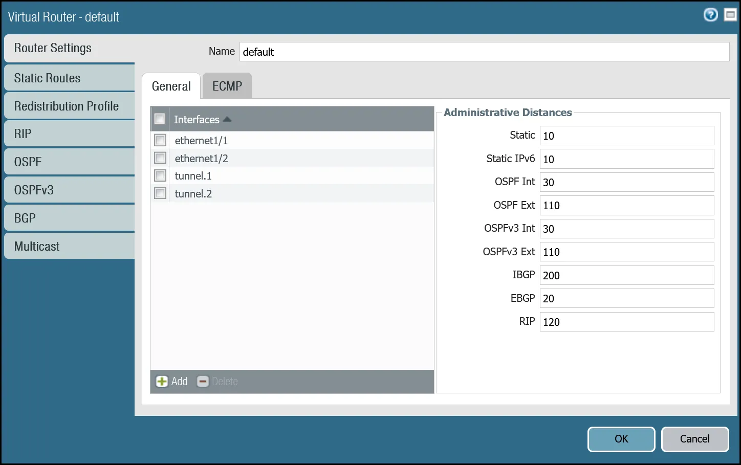
1. Open the **Router settings** for the default Virtual Router and select the **ECMP** tab.
2. Select the checkboxes next to **Enable**, **Symmetric Return**, and **Strict Source Path** (all three checkboxes should be selected).
3. Under **Load Balance**, change the **Method** from _IP Modulo_ to _Weighted Round Robin_ and add both tunnel interfaces. Ensure the weights match the weights defined in Cloudflare WAN static routes (reference the Cloudflare Dashboard).
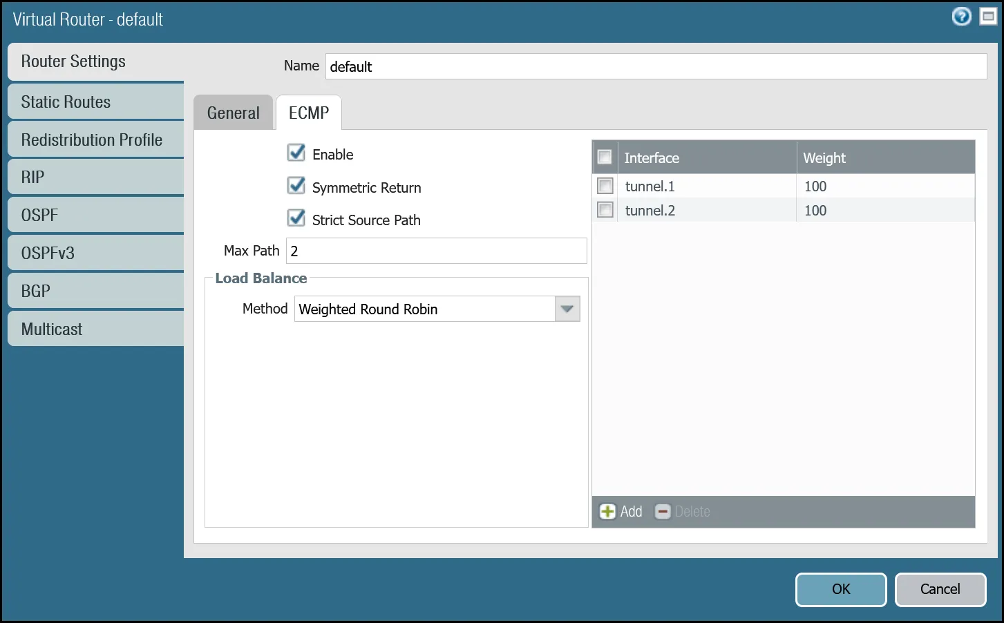
You can also use the command line to make these changes:
Terminal window
```
set network virtual-router default ecmp algorithm weighted-round-robin interface tunnel.1 weight 100
set network virtual-router default ecmp algorithm weighted-round-robin interface tunnel.2 weight 100
set network virtual-router default ecmp enable yes
set network virtual-router default ecmp symmetric-return yes
set network virtual-router default ecmp strict-source-path yes
```
#### Add static routes
Add two static routes for each Cloudflare WAN protected network - one for each of the two tunnel interfaces.
Note
Palo Alto Networks Next-Generation Firewall will not allow for configuring two routes to the same destination with equal metrics - even if they reference different interfaces and ECMP is enabled. The examples provided here use Metric 10 for the route via interface tunnel.1 and Metric 11 for the route via interface tunnel.2.
The environment used for this tutorial assumes two Cloudflare WAN protected networks:
* **VLAN0010**: `10.1.10.0/24`
* **VLAN0020**: `10.1.20.0/24`
##### VLAN0010 (`10.1.10.0/24`) via tunnel.1
| Name | Option | Value |
| ---------------------------------- | ------------- | ------------------------- |
| Magic\_WAN\_VLAN0010\_Tun01 | Destination | _VLAN0010\_10-1-10-0--24_ |
| Interface | _tunnel.1_ | |
| Next hop | _IP Address_ | |
| _CF\_MWAN\_IPsec\_VTI\_01\_Remote_ | | |
| Metric | 10 | |
| Route Table | _Unicast_ | |
| BFD Profile | _Disable BFD_ | |
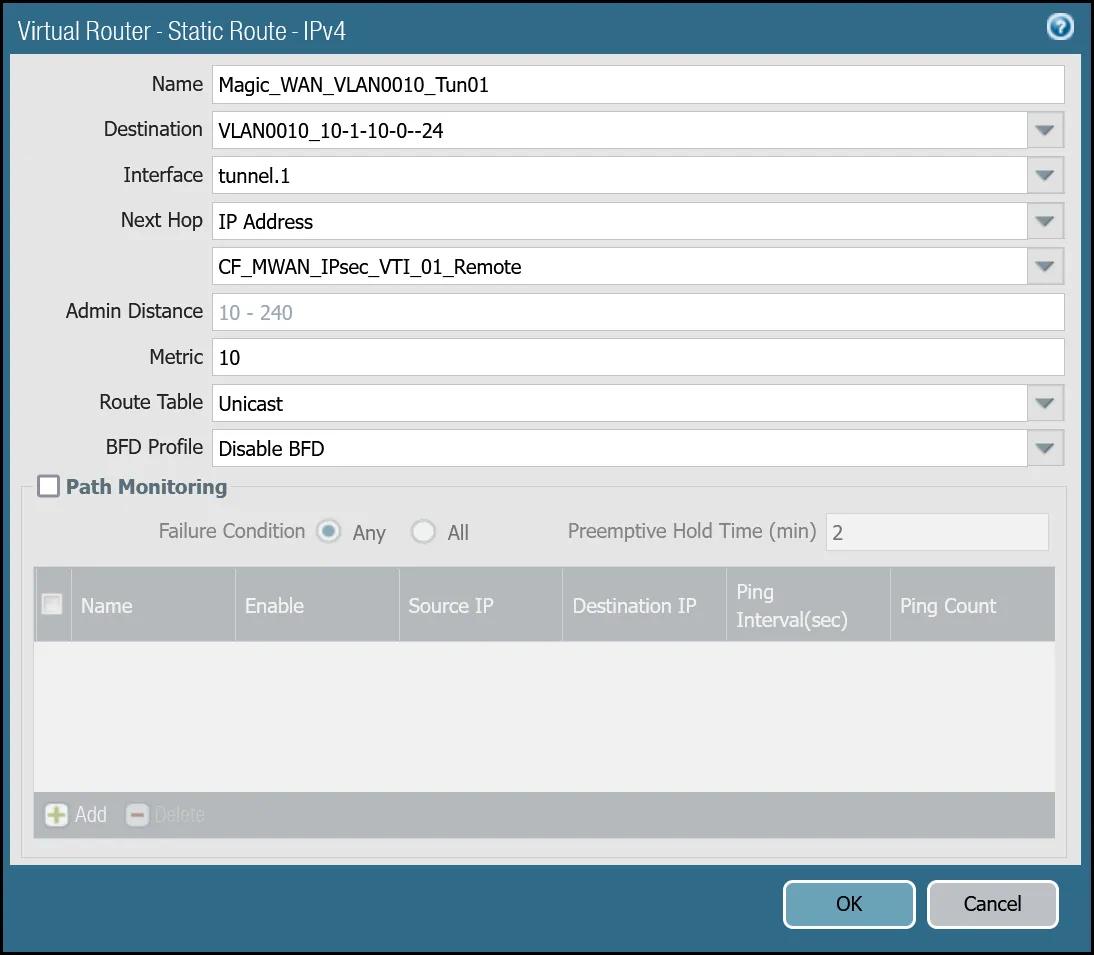
_Note: Labels in this image may reflect previous product names._
##### VLAN0010 (`10.1.10.0/24`) via tunnel.2
| Name | Option | Value |
| ---------------------------------- | ------------- | ------------------------- |
| Magic\_WAN\_VLAN0010\_Tun02 | Destination | _VLAN0010\_10-1-10-0--24_ |
| Interface | _tunnel.2_ | |
| Next hop | _IP Address_ | |
| _CF\_MWAN\_IPsec\_VTI\_02\_Remote_ | | |
| Metric | 11 | |
| Route Table | _Unicast_ | |
| BFD Profile | _Disable BFD_ | |
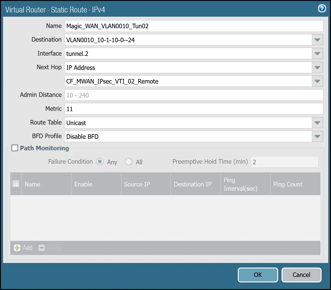
_Note: Labels in this image may reflect previous product names._
##### VLAN0020 (`10.1.20.0/24`) via tunnel.1
| Name | Option | Value |
| ---------------------------------- | ------------- | ------------------------- |
| Magic\_WAN\_VLAN0020\_Tun01 | Destination | _VLAN0020\_10-1-20-0--24_ |
| Interface | _tunnel.1_ | |
| Next hop | _IP Address_ | |
| _CF\_MWAN\_IPsec\_VTI\_01\_Remote_ | | |
| Metric | 10 | |
| Route Table | _Unicast_ | |
| BFD Profile | _Disable BFD_ | |
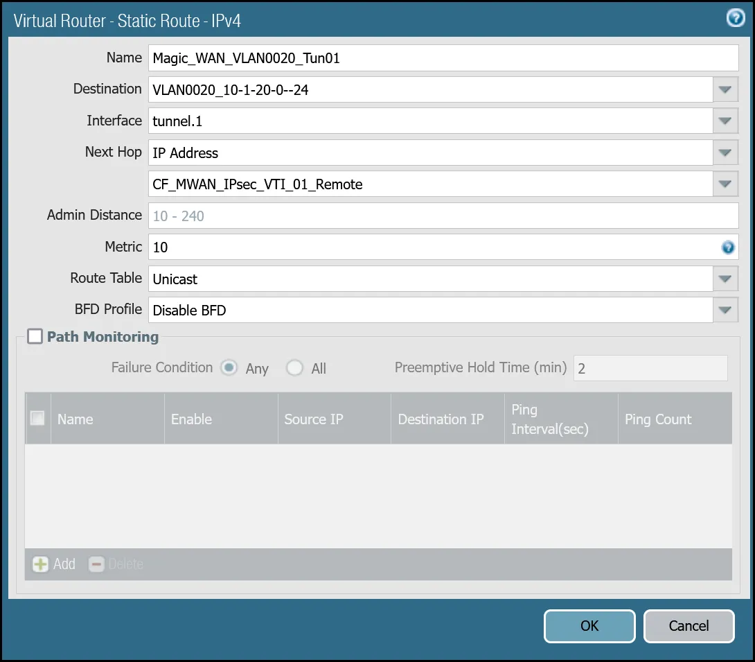
_Note: Labels in this image may reflect previous product names._
##### VLAN0020 (`10.1.20.0/24`) via tunnel.2
| Name | Option | Value |
| ---------------------------------- | ------------- | ------------------------- |
| Magic\_WAN\_VLAN0020\_Tun02 | Destination | _VLAN0020\_10-1-20-0--24_ |
| Interface | _tunnel.2_ | |
| Next hop | _IP Address_ | |
| _CF\_MWAN\_IPsec\_VTI\_02\_Remote_ | | |
| Metric | 11 | |
| Route Table | _Unicast_ | |
| BFD Profile | _Disable BFD_ | |

_Note: Labels in this image may reflect previous product names._
You can also configure these settings via command line:
##### VLAN0010 - `10.1.10.0/24`
Terminal window
```
set network virtual-router default routing-table ip static-route Magic_WAN_VLAN0010_Tun01 nexthop ip-address CF_MWAN_IPsec_VTI_01_Remote
set network virtual-router default routing-table ip static-route Magic_WAN_VLAN0010_Tun01 bfd profile None
set network virtual-router default routing-table ip static-route Magic_WAN_VLAN0010_Tun01 interface tunnel.1
set network virtual-router default routing-table ip static-route Magic_WAN_VLAN0010_Tun01 metric 10
set network virtual-router default routing-table ip static-route Magic_WAN_VLAN0010_Tun01 destination VLAN0010_10-1-10-0--24
set network virtual-router default routing-table ip static-route Magic_WAN_VLAN0010_Tun01 route-table unicast
set network virtual-router default routing-table ip static-route Magic_WAN_VLAN0010_Tun02 nexthop ip-address CF_MWAN_IPsec_VTI_02_Remote
set network virtual-router default routing-table ip static-route Magic_WAN_VLAN0010_Tun02 bfd profile None
set network virtual-router default routing-table ip static-route Magic_WAN_VLAN0010_Tun02 interface tunnel.2
set network virtual-router default routing-table ip static-route Magic_WAN_VLAN0010_Tun02 metric 11
set network virtual-router default routing-table ip static-route Magic_WAN_VLAN0010_Tun02 destination VLAN0010_10-1-10-0--24
set network virtual-router default routing-table ip static-route Magic_WAN_VLAN0010_Tun02 route-table unicast
```
##### VLAN0020 - `10.1.20.0/24`
Terminal window
```
set network virtual-router default routing-table ip static-route Magic_WAN_VLAN0020_Tun01 nexthop ip-address CF_MWAN_IPsec_VTI_01_Remote
set network virtual-router default routing-table ip static-route Magic_WAN_VLAN0020_Tun01 bfd profile None
set network virtual-router default routing-table ip static-route Magic_WAN_VLAN0020_Tun01 interface tunnel.1
set network virtual-router default routing-table ip static-route Magic_WAN_VLAN0020_Tun01 metric 10
set network virtual-router default routing-table ip static-route Magic_WAN_VLAN0020_Tun01 destination VLAN0020_10-1-20-0--24
set network virtual-router default routing-table ip static-route Magic_WAN_VLAN0020_Tun01 route-table unicast
set network virtual-router default routing-table ip static-route Magic_WAN_VLAN0020_Tun02 nexthop ip-address CF_MWAN_IPsec_VTI_02_Remote
set network virtual-router default routing-table ip static-route Magic_WAN_VLAN0020_Tun02 bfd profile None
set network virtual-router default routing-table ip static-route Magic_WAN_VLAN0020_Tun02 interface tunnel.2
set network virtual-router default routing-table ip static-route Magic_WAN_VLAN0020_Tun02 metric 11
set network virtual-router default routing-table ip static-route Magic_WAN_VLAN0020_Tun02 destination VLAN0020_10-1-20-0--24
set network virtual-router default routing-table ip static-route Magic_WAN_VLAN0020_Tun02 route-table unicast
```
### Health checks
Cloudflare crafts ICMP probes which are sent through the IPsec tunnels from random servers across Cloudflare's global anycast network. These ICMP probes are unique because an ICMP reply packet is sent (as opposed to an ICMP Request).
Note
The construct of the security policies may seem counter-intuitive - this is due to the use of ICMP reply probes. As long as you adhere to the recommended policies in this documentation, the bi-directional health checks will work as expected.
Cloudflare WAN customers must configure IPsec tunnels to use custom anycast IP addresses for the health check endpoints:
* **CF\_Health\_Check\_Anycast\_01**: `172.64.240.253`
* **CF\_Health\_Check\_Anycast\_02**: `172.64.240.254`
#### Security Policy - Tunnel health checks
You must define a rule to allow the ICMP reply probes as Palo Alto Networks Next-Generation Firewall's default behavior will drop the health checks.
Note
Cloudflare health checks are sent from random servers across Cloudflare's global network and can originate from any addresses within the Cloudflare IPv4 address space represented by the `Cloudflare_IPv4_Static_Grp`.
##### Setup via dashboard
| Name | Option | Value |
| -------------------------------- | --------------------------------------------------------------------- | ------------------------ |
| Cloudflare\_Tunnel\_Bidirect\_HC | Rule Type | _universal (default)_ |
| Description | Permit bidirectional HCs | |
| Group Rules By Tag | _None_ | |
| **Source tab** | Source Zone | **Cloudflare\_L3\_Zone** |
| Source Address | **CF\_Health\_Check\_Anycast\_01** **CF\_Health\_Check\_Anycast\_02** | |
| **Destination tab** | Destination Zone | **Cloudflare\_L3\_Zone** |
| Destination Address | **Cloudflare\_IPv4\_Static\_Grp** | |
| **Application tab** | Applications | **icmp** **ping** |
| **Actions tab** | Action | _Allow_ |
| Log Setting | **Log at Session End** | |
| Profile type | _None_ | |
| Schedule | _None_ | |
| QoS Marking | _None_ | |
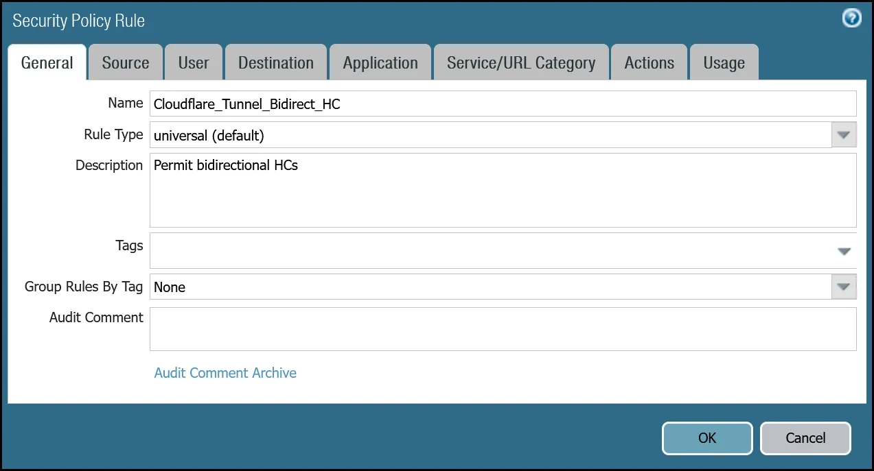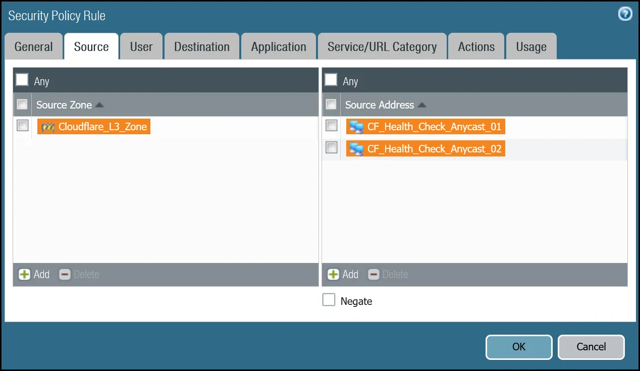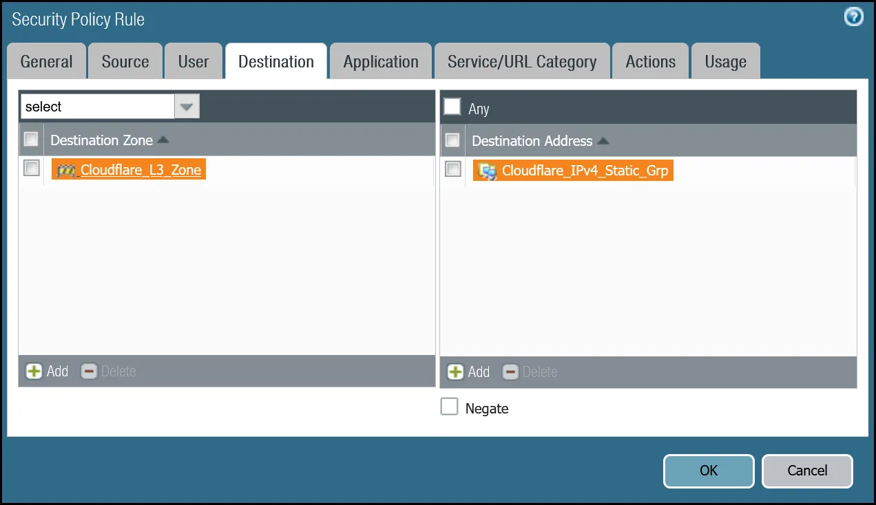
##### Setup via command line
Terminal window
```
set rulebase security rules Cloudflare_Tunnel_Bidirect_HC to Cloudflare_L3_Zone
set rulebase security rules Cloudflare_Tunnel_Bidirect_HC from Cloudflare_L3_Zone
set rulebase security rules Cloudflare_Tunnel_Bidirect_HC source [ CF_Health_Check_Anycast_01 CF_Health_Check_Anycast_02 ]
set rulebase security rules Cloudflare_Tunnel_Bidirect_HC destination Cloudflare_IPv4_Static_Grp
set rulebase security rules Cloudflare_Tunnel_Bidirect_HC source-user any
set rulebase security rules Cloudflare_Tunnel_Bidirect_HC category any
set rulebase security rules Cloudflare_Tunnel_Bidirect_HC application [ icmp ping ]
set rulebase security rules Cloudflare_Tunnel_Bidirect_HC service application-default
set rulebase security rules Cloudflare_Tunnel_Bidirect_HC hip-profiles any
set rulebase security rules Cloudflare_Tunnel_Bidirect_HC action allow
set rulebase security rules Cloudflare_Tunnel_Bidirect_HC rule-type universal
set rulebase security rules Cloudflare_Tunnel_Bidirect_HC description "Permit bidirectional HCs"
set rulebase security rules Cloudflare_Tunnel_Bidirect_HC disabled no
set rulebase security rules Cloudflare_Tunnel_Bidirect_HC log-end yes
```
Note
Logging is enabled on the rule to permit health checks. While the amount of bandwidth consumed by health checks is negligible, the flows generate a significant number of log entries. You may want to disable logging on this rule once in production, and only enable it if any troubleshooting becomes necessary.
#### Policy-based forwarding - tunnel health checks
Traffic matching the Security Rule defined in the last step must be routed symmetrically across the tunnel the ingress traffic was received through. Two policy-based forwarding rules ensure the traffic is routed accordingly.
Ensure have the following:
* **Source Zone**: `Cloudflare_L3_Zone`
* **Source Addresses**: `CF_Health_Check_Anycast_01` and `CF_Health_Check_Anycast_02`
* **Destination Zone**: `Cloudflare_L3_Zone`
* **Destination Addresses**: `Cloudflare_IPv4_Static_Grp`
* **Application**: `icmp` and `ping`
##### Set up via dashboard tunnel.1
| Name | Option | Value |
| --------------------------------------- | ---------------------------------- | --------------------------------- |
| PBF\_Cloudflare\_Health\_Check\_01 | Tags | _Cloudflare\_L3\_Zone_ |
| Group Rules By Tag | _None_ | |
| **Source tab** | Type | _Zone_ |
| Zone | **Cloudflare\_L3\_Zone** | |
| Source Address | **CF\_Health\_Check\_Anycast\_01** | |
| **Destination/Application/Service tab** | Destination Address | **Cloudflare\_IPv4\_Static\_Grp** |
| **Forwarding tab** | Action | _Forward_ |
| Egress interface | _tunnel.1_ | |
| Next Hop | _IP Address_ | |
| _CF\_MWAN\_IPsec\_VTI\_01\_Remote_ | | |
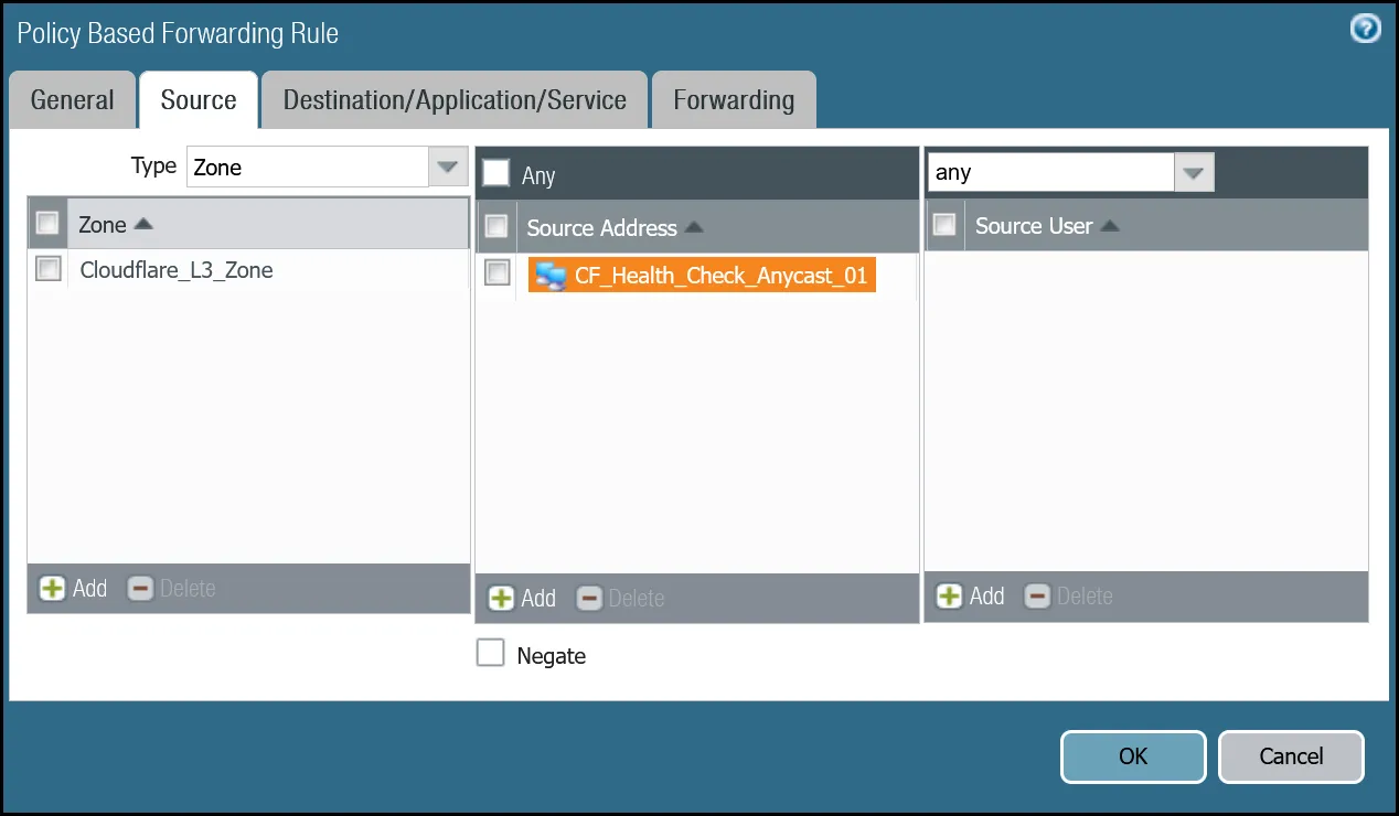
_Note: Labels in these images may reflect previous product names._
##### Set up via dashboard tunnel.2
| Name | Option | Value |
| --------------------------------------- | ---------------------------------- | --------------------------------- |
| PBF\_Cloudflare\_Health\_Check\_02 | Tags | _Cloudflare\_L3\_Zone_ |
| Group Rules By Tag | _None_ | |
| **Source tab** | Type | _Zone_ |
| Zone | **Cloudflare\_L3\_Zone** | |
| Source Address | **CF\_Health\_Check\_Anycast\_02** | |
| **Destination/Application/service tab** | Destination Address | **Cloudflare\_IPv4\_Static\_Grp** |
| **Forwarding tab** | Action | _Forward_ |
| Egress interface | _tunnel.2_ | |
| Next Hop | _IP Address_ | |
| _CF\_MWAN\_IPsec\_VTI\_02\_Remote_ | | |
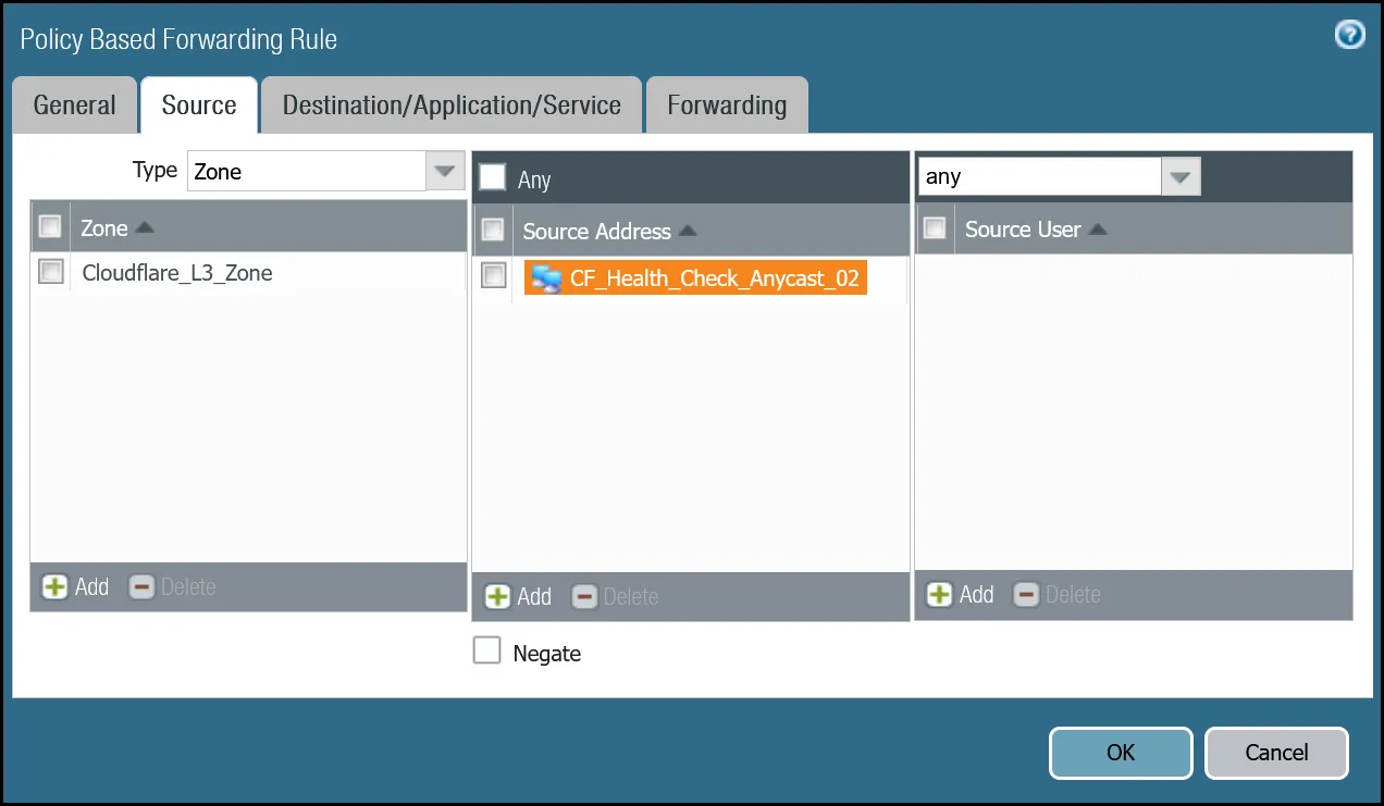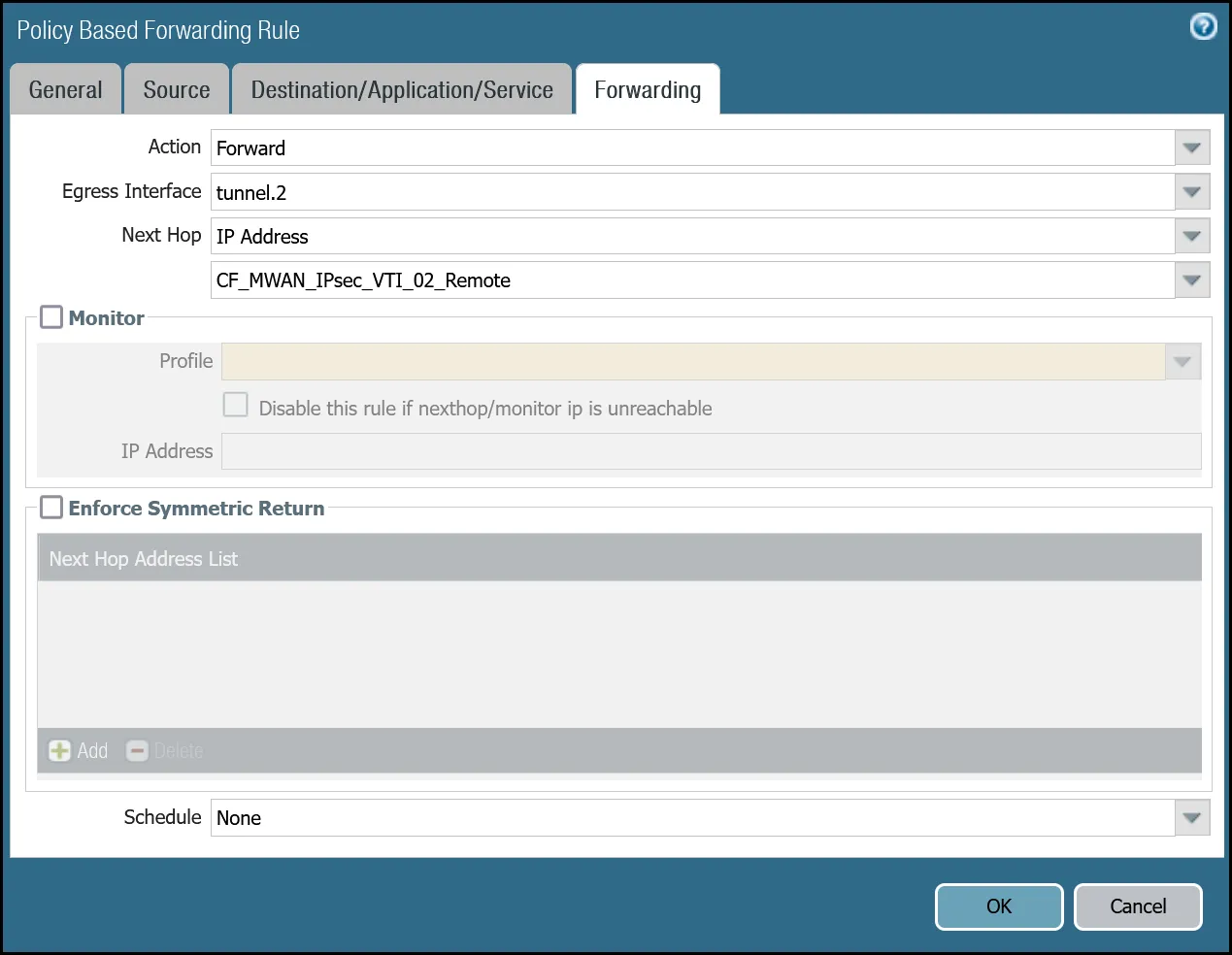
_Note: Labels in these images may reflect previous product names._
##### Set up via command line tunnel.1
Terminal window
```
set rulebase pbf rules PBF_Cloudflare_Healthcheck_01 action forward nexthop ip-address CF_MWAN_IPsec_VTI_01_Remote
set rulebase pbf rules PBF_Cloudflare_Healthcheck_01 action forward egress-interface tunnel.1
set rulebase pbf rules PBF_Cloudflare_Healthcheck_01 from zone Cloudflare_L3_Zone
set rulebase pbf rules PBF_Cloudflare_Healthcheck_01 enforce-symmetric-return enabled no
set rulebase pbf rules PBF_Cloudflare_Healthcheck_01 source CF_Health_Check_Anycast_01
set rulebase pbf rules PBF_Cloudflare_Healthcheck_01 destination Cloudflare_IPv4_Static_Grp
set rulebase pbf rules PBF_Cloudflare_Healthcheck_01 source-user any
set rulebase pbf rules PBF_Cloudflare_Healthcheck_01 application any
set rulebase pbf rules PBF_Cloudflare_Healthcheck_01 service any
set rulebase pbf rules PBF_Cloudflare_Healthcheck_01 tag Cloudflare_L3_Zone
```
##### Set up via command line tunnel.2
Terminal window
```
set rulebase pbf rules PBF_Cloudflare_Healthcheck_02 action forward nexthop ip-address CF_MWAN_IPsec_VTI_02_Remote
set rulebase pbf rules PBF_Cloudflare_Healthcheck_02 action forward egress-interface tunnel.2
set rulebase pbf rules PBF_Cloudflare_Healthcheck_02 from zone Cloudflare_L3_Zone
set rulebase pbf rules PBF_Cloudflare_Healthcheck_02 enforce-symmetric-return enabled no
set rulebase pbf rules PBF_Cloudflare_Healthcheck_02 source CF_Health_Check_Anycast_02
set rulebase pbf rules PBF_Cloudflare_Healthcheck_02 destination Cloudflare_IPv4_Static_Grp
set rulebase pbf rules PBF_Cloudflare_Healthcheck_02 source-user any
set rulebase pbf rules PBF_Cloudflare_Healthcheck_02 application any
set rulebase pbf rules PBF_Cloudflare_Healthcheck_02 service any
set rulebase pbf rules PBF_Cloudflare_Healthcheck_02 tag Cloudflare_L3_Zone
```
### Troubleshooting tunnel health checks
#### Security Policy
Use the Traffic log viewer to ensure that the health check traffic is allowed. Start by adding a rule to filter the logs based on the name of the Security Policy rule permitting the applicable traffic.
##### Filter by rule name
Terminal window
```
rule eq Cloudflare_Tunnel_Bidirect_HC
```

If you do not see any traffic matching the filter, replace the filter with one that displays log entries based on the addresses associated with the `CF_Health_Check_Anycast_01` and `CF_Health_Check_Anycast_02` Address objects.
##### Filter by health check anycast IPs
Terminal window
```
( addr.src in 172.64.240.253 ) or ( addr.src in 172.64.240.254 )
```

#### Policy-based forwarding
Troubleshooting policy-based forwarding can be a bit challenging. The ideal way to determine if traffic is flowing through the intended path is to select the detailed view for a log entry.
1. Select the magnifying glass next to one of the log entries with source IP address `172.64.240.253`.
2. Traffic originating from `CF_Health_Check_Anycast_01` (`172.64.240.253`) should ingress and egress interface tunnel.1.

1. Select the magnifying glass next to one of the log entries with source IP address `172.64.240.254`.
2. Traffic originating from `CF_Health_Check_Anycast_02` (`172.64.240.254`) should ingress and egress interface tunnel.2.

If the traffic is not ingressing/egressing the same interface, you likely have an issue with the policy-based forwarding rule(s) not matching.
### Security Policies - Production Traffic
As mentioned earlier, this tutorial includes examples for two different use-cases:
* **Cloudflare WAN**: permit traffic between two or more locations with [RFC-1918 ↗](https://datatracker.ietf.org/doc/html/rfc1918) private non-routable address space.
* **Cloudflare WAN with Cloudflare Zero Trust (Gateway egress)**: same as Cloudflare WAN with the addition of outbound Internet access from Cloudflare WAN protected sites egressing the Cloudflare edge network.
#### Cloudflare WAN only
Rules must be defined to facilitate traffic from the trust network to the Cloudflare WAN protected sites. While it may be possible to define one rule for traffic in both directions, this example includes two rules:
* From Trust to Cloudflare WAN protected sites.
* From Cloudflare WAN protected sites to Trust.
##### Trust to Cloudflare WAN dashboard
| Name | Option | Value |
| ---------------------------------------- | ------------------------------------------------------- | ------------------------ |
| Trust\_to\_Cloudflare\_Magic\_WAN\_Allow | Rule Type | _universal (default)_ |
| Group Rules by Tag | _None_ | |
| **Source tab** | Source Zone | **Trust\_L3\_Zone** |
| Source Address | **VLAN0100\_10-1-100-0--24** | |
| **Destination tab** | Destination Zone | **Cloudflare\_L3\_Zone** |
| Destination Address | **VLAN0010\_10-1-10-0--24** **VLAN0020\_10-1-20-0--24** | |
| **Actions tab** | Action | _Allow_ |
| Log Setting | **Log at Session End** | |
| Profile type | _None_ | |
| Schedule | _None_ | |
| QoS Marking | _None_ | |
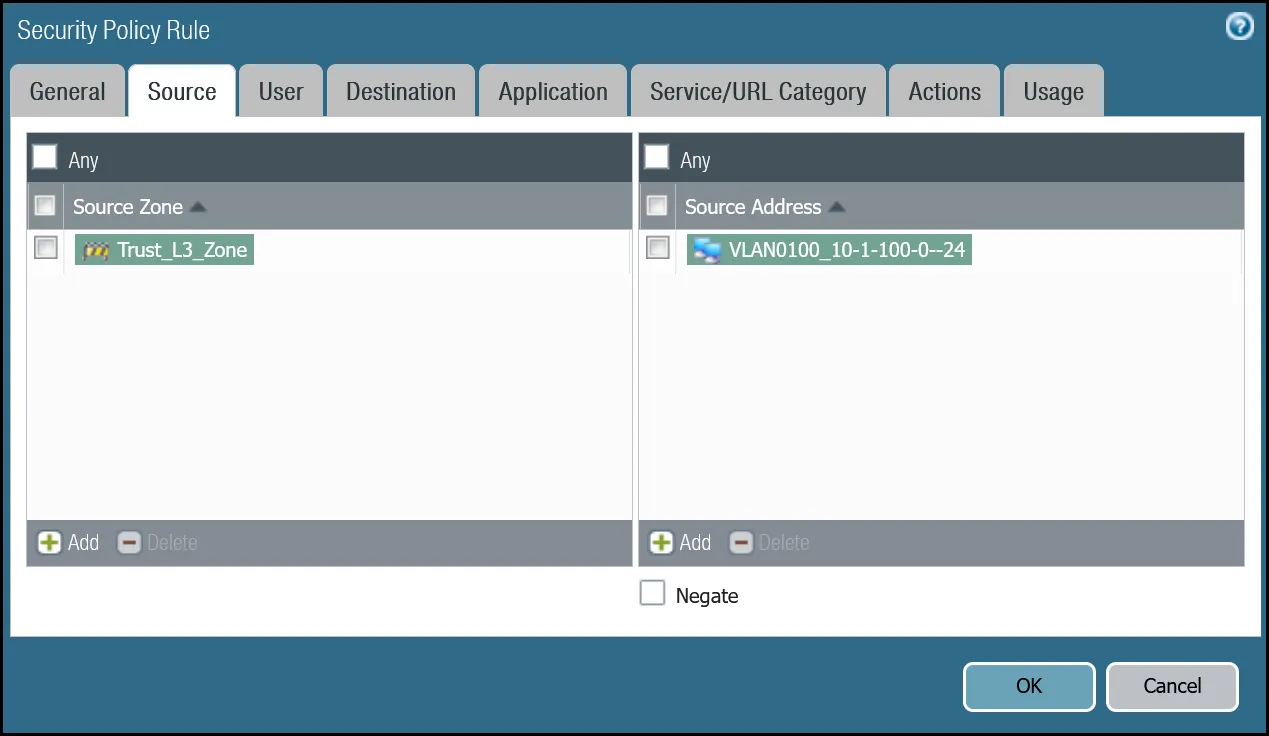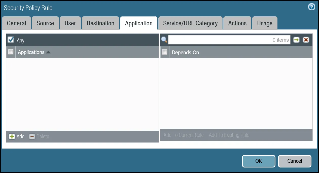
_Note: Labels in these images may reflect previous product names._
##### Trust to Cloudflare WAN command line
Terminal window
```
set rulebase security rules Trust_to_Cloudflare_Magic_WAN_Allow to Cloudflare_L3_Zone
set rulebase security rules Trust_to_Cloudflare_Magic_WAN_Allow from Trust_L3_Zone
set rulebase security rules Trust_to_Cloudflare_Magic_WAN_Allow source VLAN0100_10-1-100-0--24
set rulebase security rules Trust_to_Cloudflare_Magic_WAN_Allow destination [ VLAN0010_10-1-10-0--24 VLAN0020_10-1-20-0--24 ]
set rulebase security rules Trust_to_Cloudflare_Magic_WAN_Allow source-user any
set rulebase security rules Trust_to_Cloudflare_Magic_WAN_Allow category any
set rulebase security rules Trust_to_Cloudflare_Magic_WAN_Allow application any
set rulebase security rules Trust_to_Cloudflare_Magic_WAN_Allow service application-default
set rulebase security rules Trust_to_Cloudflare_Magic_WAN_Allow hip-profiles any
set rulebase security rules Trust_to_Cloudflare_Magic_WAN_Allow action allow
set rulebase security rules Trust_to_Cloudflare_Magic_WAN_Allow rule-type universal
```
##### Cloudflare WAN to Trust dashboard
| Name | Option | Value |
| ---------------------------------------- | ------------------------------------------------------- | ------------------------ |
| Cloudflare\_Magic\_WAN\_to\_Trust\_Allow | Rule Type | _universal (default)_ |
| Group Rules by Tag | _None_ | |
| Source tab | Source Zone | **Cloudflare\_L3\_Zone** |
| Source Address | **VLAN0010\_10-1-10-0--24** **VLAN0020\_10-1-20-0--24** | |
| Destination tab | Destination Zone | **Trust\_L3\_Zone** |
| Destination Address | **VLAN0100\_10-1-100-0--24** | |
| Actions tab | Action | _Allow_ |
| Log Setting | **Log at Session End** | |
| Profile type | _None_ | |
| Schedule | _None_ | |
| QoS Marking | _None_ | |
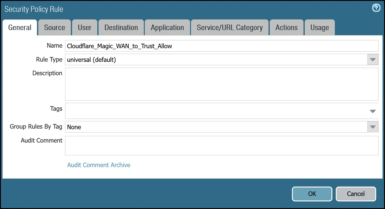
_Note: Labels in these images may reflect previous product names._
##### Cloudflare WAN to Trust command line
Terminal window
```
set rulebase security rules Cloudflare_Magic_WAN_to_Trust_Allow to Trust_L3_Zone
set rulebase security rules Cloudflare_Magic_WAN_to_Trust_Allow from Cloudflare_L3_Zone
set rulebase security rules Cloudflare_Magic_WAN_to_Trust_Allow source [ VLAN0010_10-1-10-0--24 VLAN0020_10-1-20-0--24 ]
set rulebase security rules Cloudflare_Magic_WAN_to_Trust_Allow destination VLAN0100_10-1-100-0--24
set rulebase security rules Cloudflare_Magic_WAN_to_Trust_Allow source-user any
set rulebase security rules Cloudflare_Magic_WAN_to_Trust_Allow category any
set rulebase security rules Cloudflare_Magic_WAN_to_Trust_Allow application any
set rulebase security rules Cloudflare_Magic_WAN_to_Trust_Allow service application-default
set rulebase security rules Cloudflare_Magic_WAN_to_Trust_Allow hip-profiles any
set rulebase security rules Cloudflare_Magic_WAN_to_Trust_Allow action allow
set rulebase security rules Cloudflare_Magic_WAN_to_Trust_Allow rule-type universal
```
### Policy-based forwarding - production traffic
Whether traffic ingresses or egresses Palo Alto Networks Next-Generation Firewall, it is important to ensure that traffic is routed symmetrically. This is accomplished through the use of policy-based forwarding.
Policy-based forwarding rules are only required for egress traffic.
Any traffic destined for Cloudflare WAN protected sites or Cloudflare WAN protected sites with Gateway egress must be routed across the IPsec tunnels.
Note
Security rules match traffic flows based on source and destination zone. Policy-based forwarding rules are applied per interface. Therefore, two policy-based forwarding rules are required for every one security rule - one for tunnel.1 and one for tunnel.2.
#### Dashboard policy-based forwarding - Cloudflare WAN production traffic via tunnel.1
| Name | Option | Value |
| --------------------------------------- | ---------------------------- | ------------------------------------------------------- |
| PBF\_Magic\_WAN\_Sites\_01 | Group Rules by Tag | _None_ |
| **Source tab** | Type | _Zone_ |
| Zone | **Trust\_L3\_Zone** | |
| Source Address | **VLAN0100\_10-1-100-0--24** | |
| **Destination/Application/Service tab** | Destination Address | **VLAN0010\_10-1-10-0--24** **VLAN0020\_10-1-20-0--24** |
| **Forwarding tab** | Action | _Forward_ |
| Egress Interface | _tunnel.1_ | |
| Next hop | _IP Address_ | |
| _CF\_MWAN\_IPsec\_VTI\_01\_Remote_ | | |
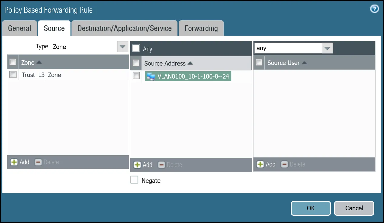
_Note: Labels in these images may reflect previous product names._
#### Command line policy-based forwarding - Cloudflare WAN production traffic via tunnel.1
Terminal window
```
set rulebase pbf rules PBF_Magic_WAN_Sites_01 action forward nexthop ip-address CF_MWAN_IPsec_VTI_01_Remote
set rulebase pbf rules PBF_Magic_WAN_Sites_01 action forward egress-interface tunnel.1
set rulebase pbf rules PBF_Magic_WAN_Sites_01 from zone Trust_L3_Zone
set rulebase pbf rules PBF_Magic_WAN_Sites_01 enforce-symmetric-return enabled no
set rulebase pbf rules PBF_Magic_WAN_Sites_01 source VLAN0100_10-1-100-0--24
set rulebase pbf rules PBF_Magic_WAN_Sites_01 destination [ VLAN0010_10-1-10-0--24 VLAN0020_10-1-20-0--24 ]
set rulebase pbf rules PBF_Magic_WAN_Sites_01 source-user any
set rulebase pbf rules PBF_Magic_WAN_Sites_01 application any
set rulebase pbf rules PBF_Magic_WAN_Sites_01 service any
set rulebase pbf rules PBF_Magic_WAN_Sites_01 disabled no
set rulebase pbf rules PBF_Magic_WAN_Sites_01 negate-destination no
```
#### Dashboard policy-based forwarding - Cloudflare WAN production traffic via tunnel.2
| Name | Option | Value |
| --------------------------------------- | ---------------------------- | ------------------------------------------------------- |
| PBF\_Magic\_WAN\_sites\_02 | Group Rules by Tag | _None_ |
| **Source tab** | Type | _Zone_ |
| Zone | **Trust\_L3\_Zone** | |
| Source Address | **VLAN0100\_10-1-100-0--24** | |
| **Destination/Application/Service tab** | Destination Address | **VLAN0010\_10-1-10-0--24** **VLAN0020\_10-1-20-0--24** |
| **Forwarding tab** | Action | _Forward_ |
| Egress Interface | _tunnel.2_ | |
| Next hop | _IP Address_ | |
| _CF\_MWAN\_IPsec\_VTI\_02\_Remote_ | | |
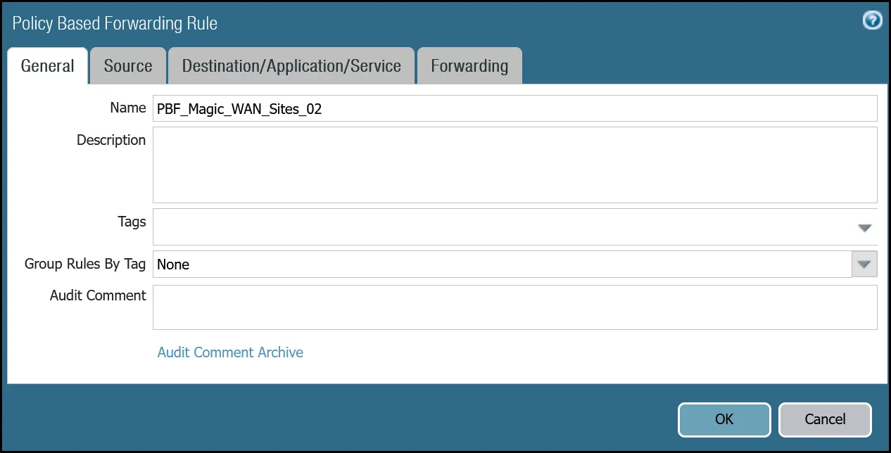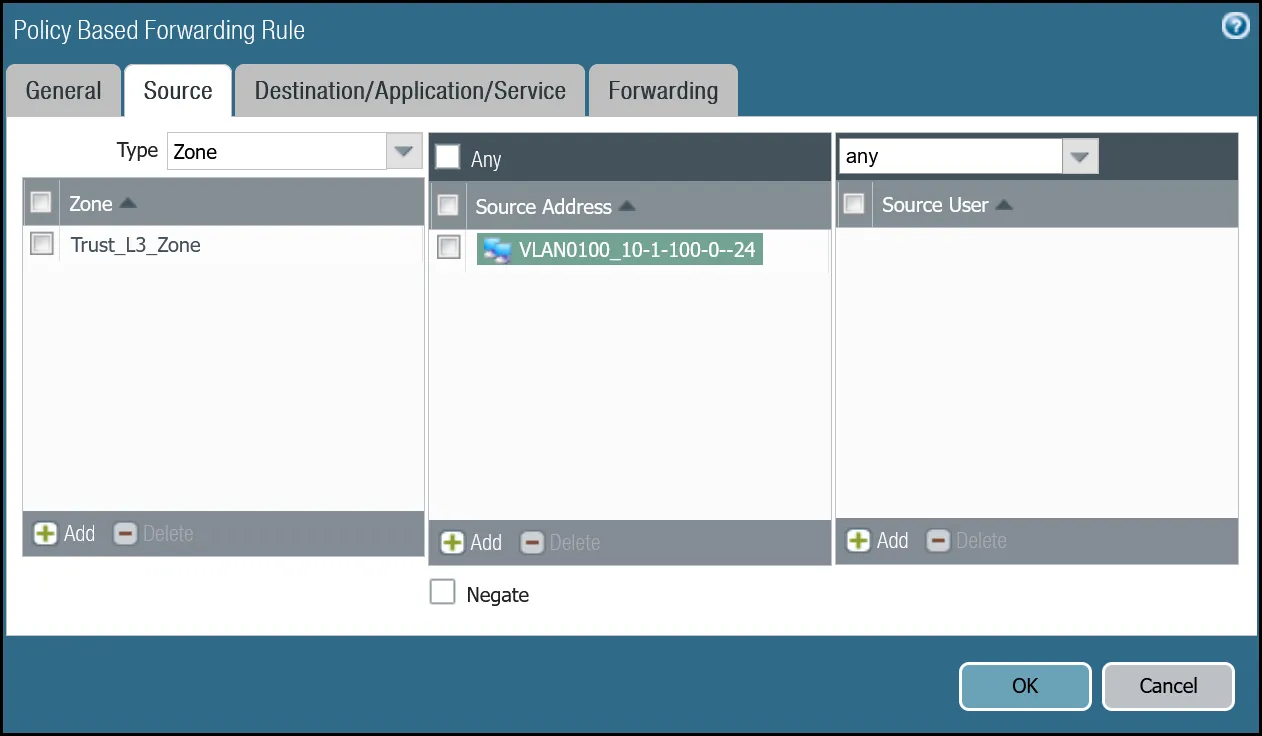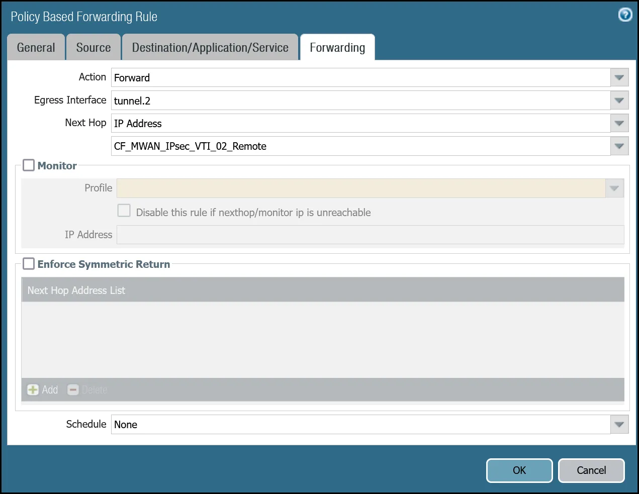
_Note: Labels in these images may reflect previous product names._
#### Command line policy-based forwarding - tunnel.2
Terminal window
```
set rulebase pbf rules PBF_Magic_WAN_Sites_02 action forward nexthop ip-address CF_MWAN_IPsec_VTI_02_Remote
set rulebase pbf rules PBF_Magic_WAN_Sites_02 action forward egress-interface tunnel.2
set rulebase pbf rules PBF_Magic_WAN_Sites_02 from zone Trust_L3_Zone
set rulebase pbf rules PBF_Magic_WAN_Sites_02 enforce-symmetric-return enabled no
set rulebase pbf rules PBF_Magic_WAN_Sites_02 source VLAN0100_10-1-100-0--24
set rulebase pbf rules PBF_Magic_WAN_Sites_02 destination [ VLAN0010_10-1-10-0--24 VLAN0020_10-1-20-0--24 ]
set rulebase pbf rules PBF_Magic_WAN_Sites_02 source-user any
set rulebase pbf rules PBF_Magic_WAN_Sites_02 application any
set rulebase pbf rules PBF_Magic_WAN_Sites_02 service any
set rulebase pbf rules PBF_Magic_WAN_Sites_02 disabled no
set rulebase pbf rules PBF_Magic_WAN_Sites_02 negate-destination no
```
## Cloudflare WAN with Cloudflare Zero Trust (Gateway egress)
This section covers adding in support for the use of Cloudflare Gateway. Adding Cloudflare Gateway allows you to set up policies to inspect outbound traffic to the Internet through DNS, network, HTTP and egress filtering.
This use case can be supported in one of two ways:
* **Option 1**
* **Security Rule**: Extend the scope of the `Trust_to_Cloudflare_Magic_WAN_Allow` rule to allow any destination address.
* **Policy-Based Forwarding**: Extend the scope of `PBF_Magic_WAN_Sites_01` and `PBF_Magic_WAN_Sites_02` to allow any destination address.
* **Option 2**
* **Security Rule**: Add a new rule below `Trust_to_Cloudflare_Magic_WAN_Allow` called `Trust_to_MWAN_Gateway_Egress_Allow` to allow traffic to any destination address except for the Cloudflare WAN protected sites (using the Negate option).
* **Policy-Based Forwarding**: Add a new rule below `PBF_Magic_WAN_Sites_01` and `PBF_Magic_WAN_Sites_02` to allow any destination address except for the Cloudflare WAN protected sites (using the Negate option).
The following examples are based on Option 2.
Note
This example assumes the security rules and policy-based forwarding rules from the previous sections have been configured and are directly above the rules configured in this section.
Also, traffic from Trust to the Internet would typically be defined as `Trust_L3_Zone` to `Untrust_L3_Zone`. However, since egress Internet traffic will be routed through the IPsec tunnels, the rule must reference `Trust_L3_Zone` to `Cloudflare_L3_Zone`.
### Security Rule: Trust to Gateway Egress
#### Dashboard
| Name | Option | Value |
| --------------------------------------- | ------------------------------------------------------------------ | ------------------------ |
| Trust\_to\_MWAN\_Gateway\_Egress\_Allow | Rule Type | _universal (default)_ |
| Group Rules By Tag | _None_ | |
| **Source tab** | Source Zone | **Trust\_L3\_Zone** |
| **Destination tab** | Destination Zone | **Cloudflare\_L3\_Zone** |
| Destination Address | **VLAN0010\_10-1-10-0--24** **VLAN0020\_10-1-20-0--24** **Negate** | |
| **Actions tab** | Action | _Allow_ |
| Log Setting | **Log at Session End** | |
| Profile Type | _None_ | |
| Schedule | _None_ | |
| QoS Marking | _None_ | |

_Note: Labels in these images may reflect previous product names._
#### Command line
Terminal window
```
set rulebase security rules Trust_to_MWAN_Gateway_Egress_Allow to Cloudflare_L3_Zone
set rulebase security rules Trust_to_MWAN_Gateway_Egress_Allow from Trust_L3_Zone
set rulebase security rules Trust_to_MWAN_Gateway_Egress_Allow source any
set rulebase security rules Trust_to_MWAN_Gateway_Egress_Allow destination [ VLAN0010_10-1-10-0--24 VLAN0020_10-1-20-0--24 ]
set rulebase security rules Trust_to_MWAN_Gateway_Egress_Allow source-user any
set rulebase security rules Trust_to_MWAN_Gateway_Egress_Allow category any
set rulebase security rules Trust_to_MWAN_Gateway_Egress_Allow application any
set rulebase security rules Trust_to_MWAN_Gateway_Egress_Allow service application-default
set rulebase security rules Trust_to_MWAN_Gateway_Egress_Allow hip-profiles any
set rulebase security rules Trust_to_MWAN_Gateway_Egress_Allow action allow
set rulebase security rules Trust_to_MWAN_Gateway_Egress_Allow rule-type universal
set rulebase security rules Trust_to_MWAN_Gateway_Egress_Allow negate-destination yes
```
### Policy-based forwarding: Trust to Gateway egress via tunnel.1
#### Dashboard
| Name | Option | Value |
| --------------------------------------- | ------------------- | ------------------------------------------------------------------ |
| PBF\_MWAN\_Egress01 | Group Rules By Tag | _None_ |
| **Source tab** | Source Zone | **Trust\_L3\_Zone** |
| **Destination/Application/Service tab** | Destination Address | **VLAN0010\_10-1-10-0--24** **VLAN0020\_10-1-20-0--24** **Negate** |
| **Forwarding tab** | Action | _Forward_ |
| Egress Interface | _tunnel.1_ | |
| Next Hop | _IP Address_ | |
| _CF\_MWAN\_IPsec\_VTI\_01\_Remote_ | | |

_Note: Labels in these images may reflect previous product names._
#### Command line
Terminal window
```
set rulebase pbf rules PBF_MWAN_Egress_01 action forward nexthop ip-address CF_MWAN_IPsec_VTI_01_Remote
set rulebase pbf rules PBF_MWAN_Egress_01 action forward egress-interface tunnel.1
set rulebase pbf rules PBF_MWAN_Egress_01 from zone Trust_L3_Zone
set rulebase pbf rules PBF_MWAN_Egress_01 enforce-symmetric-return enabled no
set rulebase pbf rules PBF_MWAN_Egress_01 source VLAN0100_10-1-100-0--24
set rulebase pbf rules PBF_MWAN_Egress_01 destination [ VLAN0010_10-1-10-0--24 VLAN0020_10-1-20-0--24 ]
set rulebase pbf rules PBF_MWAN_Egress_01 source-user any
set rulebase pbf rules PBF_MWAN_Egress_01 application any
set rulebase pbf rules PBF_MWAN_Egress_01 service any
set rulebase pbf rules PBF_MWAN_Egress_01 disabled no
set rulebase pbf rules PBF_MWAN_Egress_01 negate-destination yes
```
### Policy-based forwarding: Trust to Gateway egress via tunnel.2
#### Dashboard
| Name | Option | Value |
| --------------------------------------- | ---------------------------- | ------------------------------------------------------------------ |
| PBF\_MWAN\_Egress02 | Group Rules By Tag | _None_ |
| **Source tab** | Source Zone | **Trust\_L3\_Zone** |
| Source Address | **VLAN0100\_10-1-100-0--24** | |
| **Destination/Application/Service tab** | Destination Address | **VLAN0010\_10-1-10-0--24** **VLAN0020\_10-1-20-0--24** **Negate** |
| **Forwarding tab** | Action | _Forward_ |
| Egress Interface | _tunnel.2_ | |
| Next Hop | _IP Address_ | |
| _CF\_MWAN\_IPsec\_VTI\_02\_Remote_ | | |

_Note: Labels in these images may reflect previous product names._
#### Command line
Terminal window
```
set rulebase pbf rules PBF_MWAN_Egress_02 action forward nexthop ip-address CF_MWAN_IPsec_VTI_02_Remote
set rulebase pbf rules PBF_MWAN_Egress_02 action forward egress-interface tunnel.2
set rulebase pbf rules PBF_MWAN_Egress_02 from zone Trust_L3_Zone
set rulebase pbf rules PBF_MWAN_Egress_02 enforce-symmetric-return enabled no
set rulebase pbf rules PBF_MWAN_Egress_02 source VLAN0100_10-1-100-0--24
set rulebase pbf rules PBF_MWAN_Egress_02 destination [ VLAN0010_10-1-10-0--24 VLAN0020_10-1-20-0--24 ]
set rulebase pbf rules PBF_MWAN_Egress_02 source-user any
set rulebase pbf rules PBF_MWAN_Egress_02 application any
set rulebase pbf rules PBF_MWAN_Egress_02 service any
set rulebase pbf rules PBF_MWAN_Egress_02 disabled no
set rulebase pbf rules PBF_MWAN_Egress_02 negate-destination yes
```
## Troubleshooting
Cloudflare recommends you consult [PAN-OS 9.1 Administrators Guide - Interpret VPN Error Messages ↗](https://docs.paloaltonetworks.com/pan-os/9-1/pan-os-admin/vpns/set-up-site-to-site-vpn/interpret-vpn-error-messages) and [PAN-OS 10.2 Administrators Guide - Interpret VPN Error Messages ↗](https://docs.paloaltonetworks.com/pan-os/10-2/pan-os-admin/vpns/set-up-site-to-site-vpn/interpret-vpn-error-messages) for general troubleshooting.
```json
{"@context":"https://schema.org","@type":"BreadcrumbList","itemListElement":[{"@type":"ListItem","position":1,"item":{"@id":"/directory/","name":"Directory"}},{"@type":"ListItem","position":2,"item":{"@id":"/cloudflare-wan/","name":"Cloudflare WAN"}},{"@type":"ListItem","position":3,"item":{"@id":"/cloudflare-wan/configuration/","name":"Configuration"}},{"@type":"ListItem","position":4,"item":{"@id":"/cloudflare-wan/configuration/manually/","name":"Manual configuration"}},{"@type":"ListItem","position":5,"item":{"@id":"/cloudflare-wan/configuration/manually/third-party/","name":"Third-party integration"}},{"@type":"ListItem","position":6,"item":{"@id":"/cloudflare-wan/configuration/manually/third-party/palo-alto/","name":"Palo Alto Networks NGFW"}}]}
```
---
---
title: pfSense
description: This tutorial includes the steps required to configure IPsec tunnels to connect a pfSense firewall to Cloudflare WAN (formerly Magic WAN).
image: https://developers.cloudflare.com/zt-preview.png
---
[Skip to content](#%5Ftop)
Was this helpful?
YesNo
[ Edit page ](https://github.com/cloudflare/cloudflare-docs/edit/production/src/content/docs/cloudflare-wan/configuration/manually/third-party/pfsense.mdx) [ Report issue ](https://github.com/cloudflare/cloudflare-docs/issues/new/choose)
Copy page
# pfSense
**Last reviewed:** almost 2 years ago
This tutorial includes the steps required to configure IPsec tunnels to connect a pfSense firewall to Cloudflare WAN (formerly Magic WAN).
## Software tested
| Manufacturer | Firmware revision |
| ------------ | ----------------- |
| pfSense | 24.03 |
## Prerequisites
This tutorial requires the following information:
* Anycast IP addresses (Cloudflare provides these)
* External IP addresses
* Internal IP address ranges
* Inside tunnel `/31` ranges
## Example scenario
This tutorial uses the following IP addresses. These examples replace legally routable IP addresses with IPv4 Address Blocks Reserved for Documentation ([RFC 5737 ↗](https://datatracker.ietf.org/doc/html/rfc5737)) addresses within the `203.0.113.0/24` subnet.
| Tunnel name | PF\_TUNNEL\_01 | PF\_TUNNEL\_02 |
| --------------------------------------- | ------------------------------- | ------------------------------- |
| Interface address | 10.252.2.26/31 | 10.252.2.28/31 |
| Customer endpoint | 203.0.113.254 | 203.0.113.254 |
| Cloudflare endpoint | | |
| pfSense IPsec Phase 2 Local IP | 10.252.2.27 | 10.252.2.29 |
| pfSense IPsec Phase 2 Remote IP | 10.252.2.26 | 10.252.2.28 |
| Cloudflare WAN static routes - Prefix | 10.1.100.0/24 | 10.1.100.0/24 |
| Cloudflare WAN static routes - Next hop | PF\_TUNNEL\_01 | PF\_TUNNEL\_02 |
## 1\. Configure Cloudflare WAN IPsec tunnels
Use the Cloudflare dashboard or API to [configure two IPsec tunnels](https://developers.cloudflare.com/cloudflare-wan/configuration/manually/how-to/configure-tunnel-endpoints/#add-tunnels). This guide uses the settings mentioned below for the IPsec tunnels throughout the remainder.
### Add IPsec tunnels
1. Follow the [Add tunnels](https://developers.cloudflare.com/cloudflare-wan/configuration/manually/how-to/configure-tunnel-endpoints/#add-tunnels) instructions to create the required IPsec tunnels with the following options:
* **Tunnel name**: `PF_TUNNEL_01`
* **Interface address**: `10.252.2.26/31`
* **Customer endpoint**: `203.0.113.254`
* **Cloudflare endpoint**: Enter one of the anycast IP addresses assigned to your account, available in [Leased IPs ↗](https://dash.cloudflare.com/?to=/:account/ip-addresses/address-space).
* **Health check rate**: _Medium_
* **Health check type**: _Request_
* **Health check direction**: _Bidirectional_
* **Turn on replay protection**: Enable
2. Select **Add pre-shared key later** \> **Add tunnels**.
3. Repeat the process to create a second IPsec tunnel with the following options:
* **Tunnel name**: `PF_TUNNEL_02`
* **Interface address**: `10.252.2.28/31`
* **Customer endpoint**: `203.0.113.254`
* **Cloudflare endpoint**: Enter the second anycast IP address assigned to your account.
* **Health check rate**: _Medium_
* **Health check type**: _Request_
* **Health check direction**: _Bidirectional_
* **Turn on replay protection**: Enable
4. Select **Add pre-shared key later** \> **Add tunnels**.
Note
If site-to-site traffic is a requirement, enable replay protection. Refer to [Add tunnels](https://developers.cloudflare.com/cloudflare-wan/configuration/manually/how-to/configure-tunnel-endpoints/#add-tunnels) \> IPsec tunnel to learn how to enable this feature.
### Generate pre-shared keys
When creating IPsec tunnels with the option **Add pre-shared key later**, the Cloudflare dashboard will show a warning indicator.
1. Select **Edit** to edit the properties of each IPsec tunnel.
2. Select **Generate a new pre-shared key** \> **Update and generate pre-shared key**.
3. Copy the pre-shared key value for each IPsec tunnel, and save these values. Then, select **Done**.
Note
Take note of the pre-shared keys to use later in pfSense.
### IPsec identifier - User ID
After creating IPsec tunnels, the Cloudflare dashboard will list them under **Tunnels**. To retrieve the IPsec tunnel's user ID:
1. Go to the **Connectors** page.
[ Go to **Connectors** ](https://dash.cloudflare.com/?to=/:account/magic-networks/connections)
1. In the **IPsec/GRE tunnels** tab, select the IPsec tunnel.
2. Scroll to **User ID** and copy the string. For example, `ipsec@long_string_of_letters_and_numbers`.
Configuring IKE Phase 1 on the pfSense firewall requires the User ID.
## 2\. Create Cloudflare WAN static routes
Create a [static route](https://developers.cloudflare.com/cloudflare-wan/configuration/manually/how-to/configure-routes/#create-a-static-route) for each of the two IPsec tunnels configured in the previous section, with the following settings (settings not mentioned here can be left with their default values):
### Tunnel 01
* **Description**: `PF_TUNNEL_01`
* **Prefix**: `10.1.100.0/24`
* **Tunnel/Next hop**: `PF_TUNNEL_01`
### Tunnel 02
* **Description**: `PF_TUNNEL_02`
* **Prefix**: `10.1.100.0/24`
* **Tunnel/Next hop**: `PF_TUNNEL_02`
## 3\. Configure the pfSense firewall
Install pfSense and boot up. Then, assign and set LAN and WAN interfaces, as well as IP addresses. For example:
* **LAN**: `203.0.113.254`
* **WAN**: ``
### Configure IPsec Phase 1
Add a new IPsec tunnel [Phase 1 entry ↗](https://docs.netgate.com/pfsense/en/latest/vpn/ipsec/configure-p1.html), with the following settings:
* **General Information**
* **Description**: `CF1_IPsec_P1`
* **IKE Endpoint Configuration**
* **Key exchange version**: _IKE\_v2_
* **Internet Protocol**: _IPv4_
* **Interface**: _WAN_
* **Remote gateway**: Enter the Cloudflare Anycast IP address.
* **Phase 1 Proposal (Authentication)**
* **Authentication method**: _Mutual PSK_
* **My identifier**: _User Fully qualified domain name_ \> `ipsec@long_string_of_letters_and_numbers`
(Find this identifier in the Cloudflare IPsec tunnel configuration > **User ID**)
* **Peer identifier**: _Peer IP Address_ (Cloudflare Anycast IP)
* **Pre-Shared Key (PSK)**: Enter the pre-shared key from the Cloudflare IPsec tunnel.
* **Phase 1 proposal (Encryption algorithm)**
* **Encryption algorithm**: _AES 256 bits_
* **Key length**: _256 bits_
* **Hash algorithm**: _SHA256_
* **DH key group**: _20_
* **Lifetime**: `86400`
### Configure IPsec Phase 2
Add a new IPsec tunnel [Phase 2 entry ↗](https://docs.netgate.com/pfsense/en/latest/vpn/ipsec/configure-p2.html), with the following settings. Create two separate Phase 2 entries (one for tunnel 1 and one for tunnel 2), adjusting the IP addresses for local and remote networks accordingly:
* **General Information**
* **Description**: `CF1_IPsec_P2`
* **Mode**: _Routed (VTI)_ (Virtual Tunnel Interface)
* **Networks**
* **Local Network**: _Address_ \> Higher IP address in the `/31` assigned in Cloudflare tunnel. For example, `10.252.2.27` for tunnel 1 and `10.252.2.29` for tunnel 2.
* **Remote Network**: _Address_ \> Lower IP address in the `/31` for Cloudflare side. For example, `10.252.2.26` for tunnel 1, and `10.252.2.28` for tunnel 2.
* **Phase 2 Proposal (SA/Key Exchange)**
* **Protocol**: _ESP_ (Encapsulating Security Payload)
* **Encryption algorithm**: _AES 256 bits_
* **Hash algorithm**: _SHA256_
* **DH key group**: _20_
* **Lifetime**: `28800`
Apply the changes. Navigate to **Status** \> **IPsec** to verify that both Phase 1 and Phase 2 are connected.
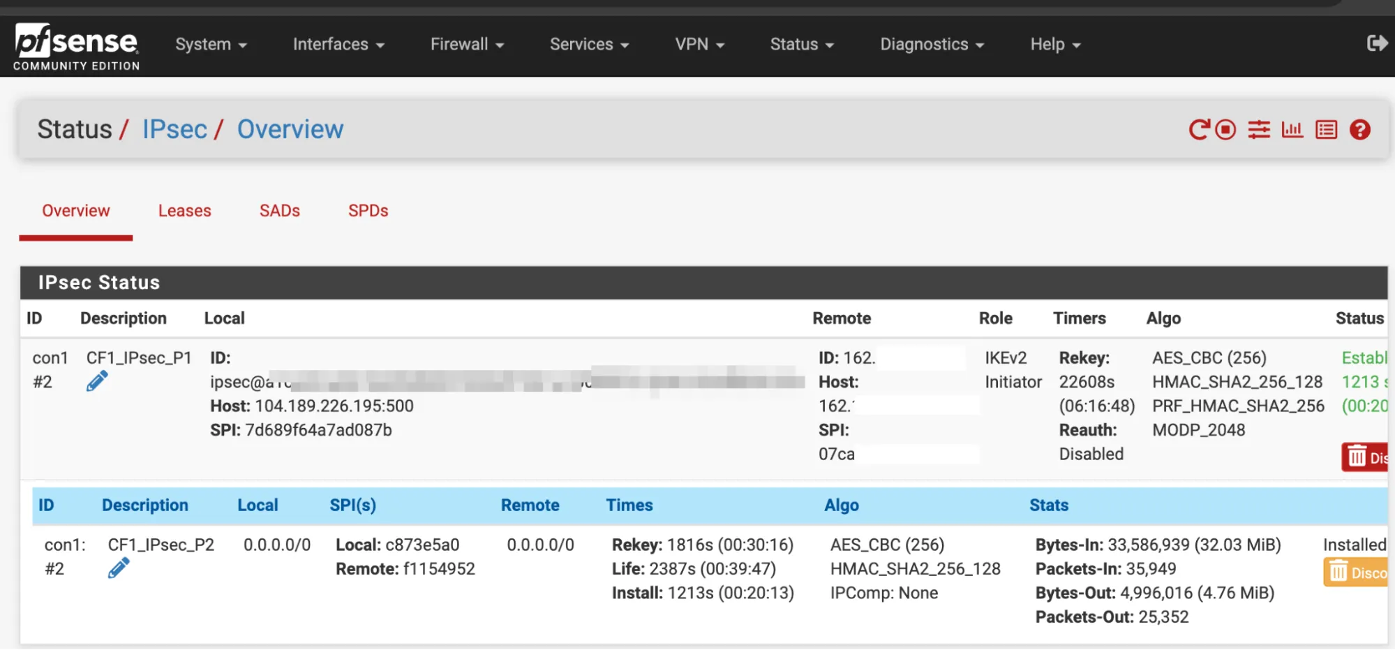
### Interface assignments
In **Interfaces** \> **Assignments** \> **Add**, create a new interface to assign to the first IPsec tunnel, with the following settings:
* **General configuration**
* **Description**: `CF1_IPsec_1`
* **MSS**: `1446`
* **Interface Assignments**
* **WAN**: Add the WAN interface. For example, `vnet1`.
* **LAN**: Add the LAN interface. For example, `vnet0`.
* Add the **CF\_IPsec\_1** interface from Phase 1 above.
Select **Save** to apply the changes.
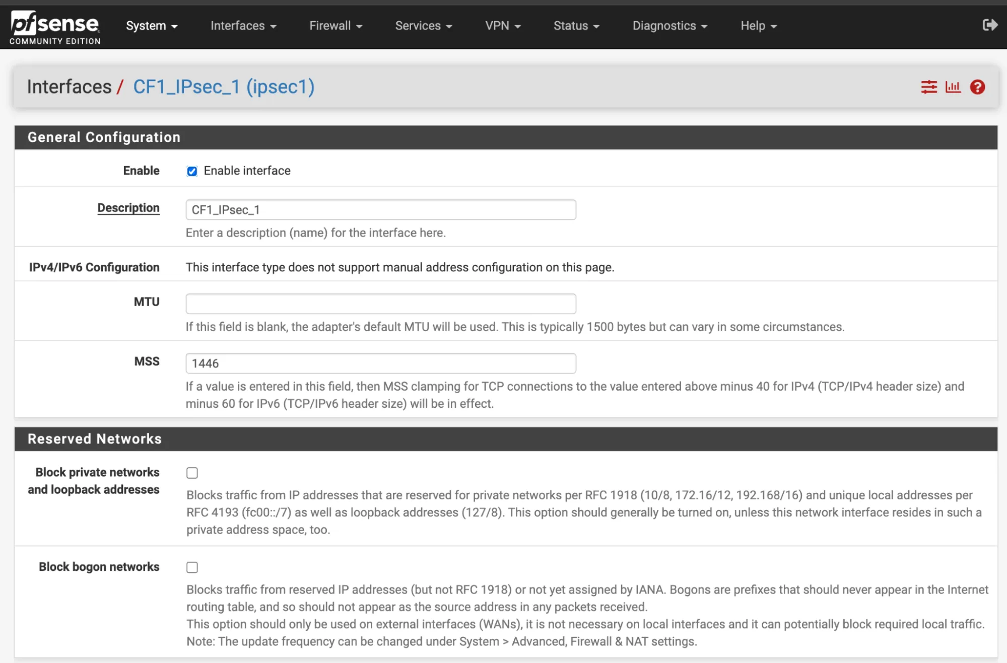
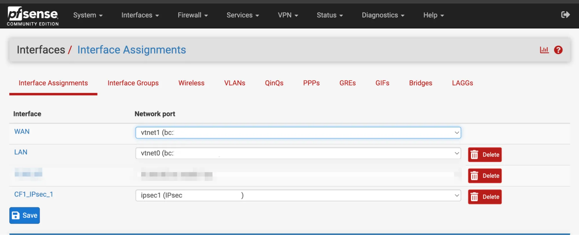
### Gateway
In **System** \> **Routing** \> **Gateways** there should already be a gateway. For this example, it is named `CF1_IPSEC_1_VTIV4`.
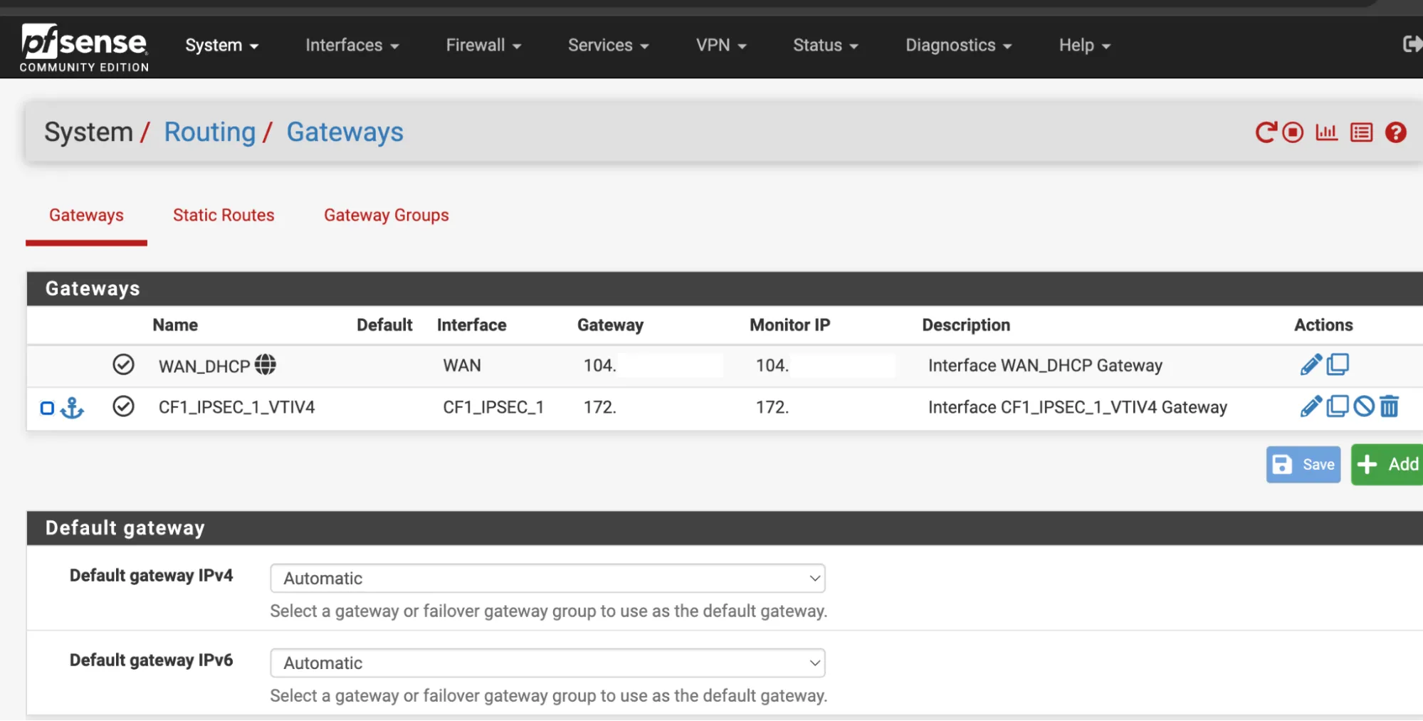
### Firewall Rules IPsec
1. In **Firewall Rules** \> **IPsec interface**, allow any type of traffic.
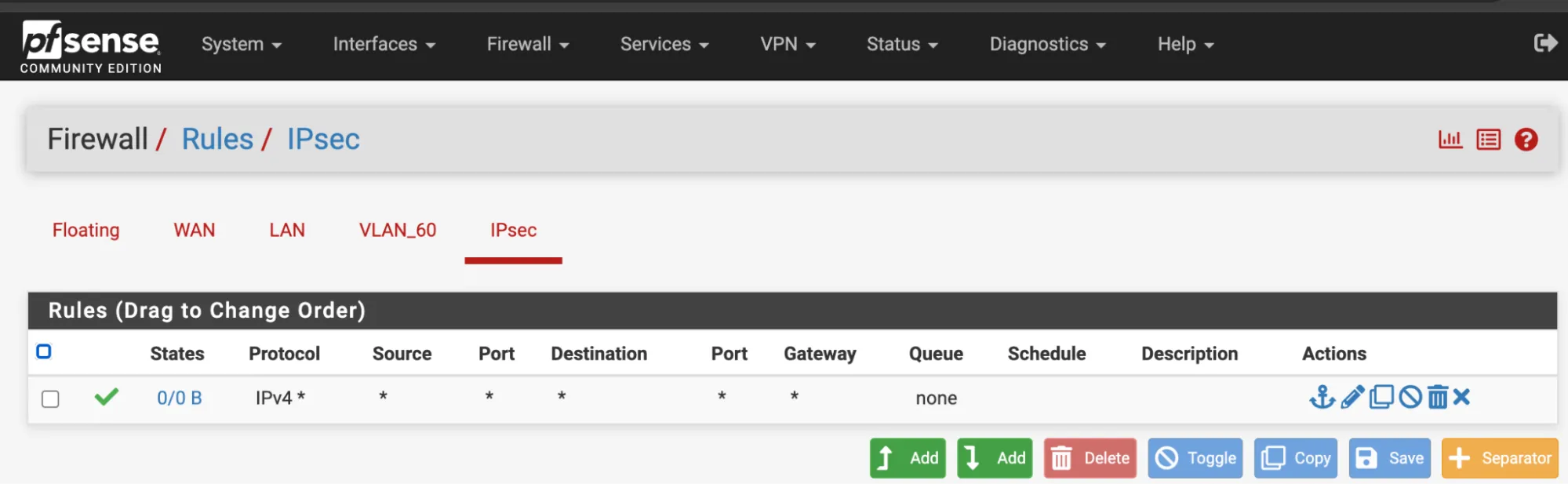
1. Navigate to **Status** \> **Gateways**. `CF1_IPSEC_1_VTIV4` should now be online.
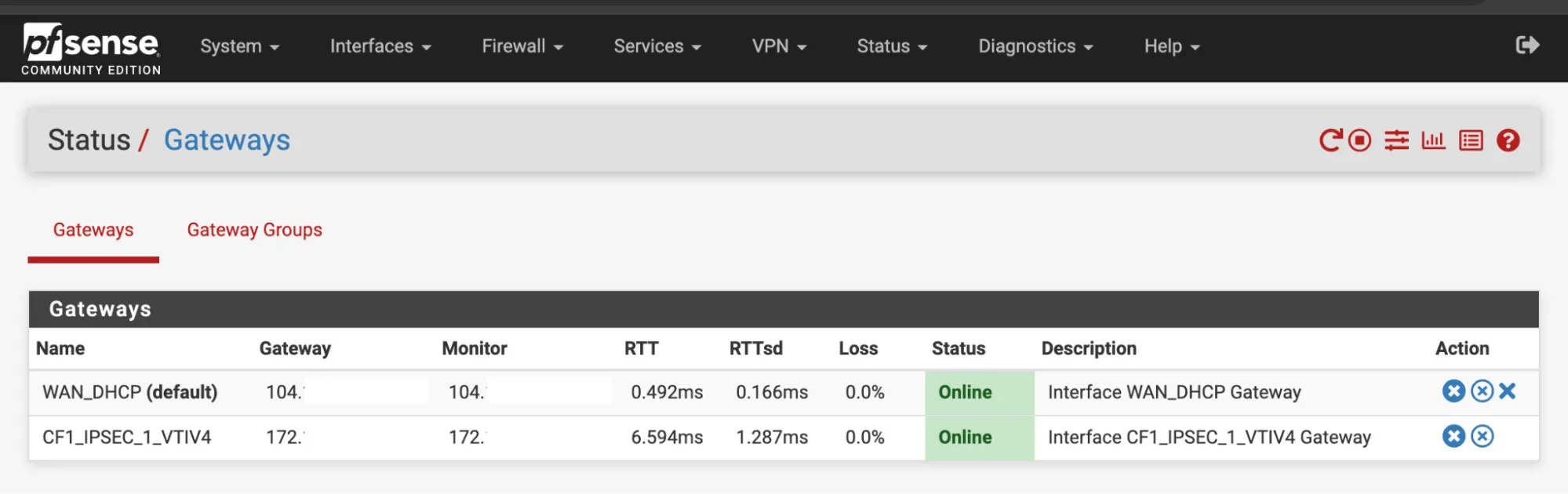
### Firewall Rules LAN
1. In **Firewall** \> **Rules** \> **LAN**, allow any type of traffic.
2. Expand the **Advanced** section.
3. Change the Gateway to `CF1_IPSEC_1_VTIV4`.
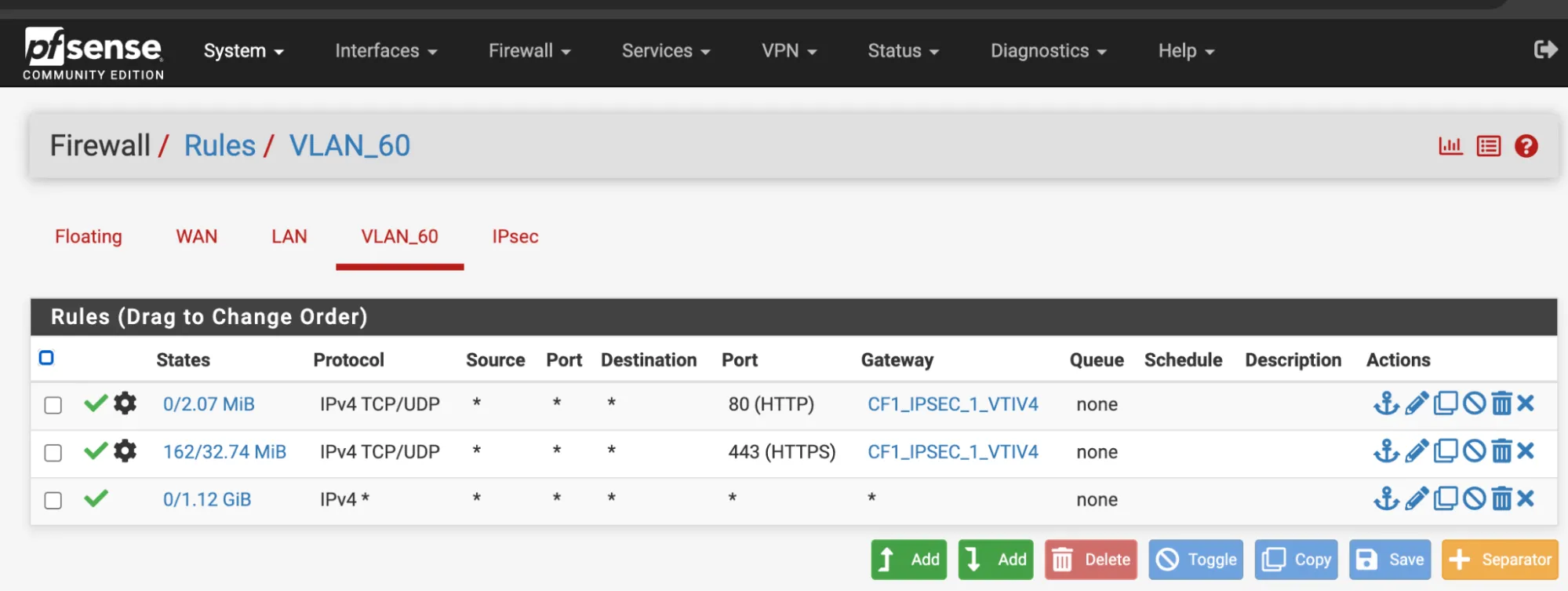
```json
{"@context":"https://schema.org","@type":"BreadcrumbList","itemListElement":[{"@type":"ListItem","position":1,"item":{"@id":"/directory/","name":"Directory"}},{"@type":"ListItem","position":2,"item":{"@id":"/cloudflare-wan/","name":"Cloudflare WAN"}},{"@type":"ListItem","position":3,"item":{"@id":"/cloudflare-wan/configuration/","name":"Configuration"}},{"@type":"ListItem","position":4,"item":{"@id":"/cloudflare-wan/configuration/manually/","name":"Manual configuration"}},{"@type":"ListItem","position":5,"item":{"@id":"/cloudflare-wan/configuration/manually/third-party/","name":"Third-party integration"}},{"@type":"ListItem","position":6,"item":{"@id":"/cloudflare-wan/configuration/manually/third-party/pfsense/","name":"pfSense"}}]}
```
---
---
title: SonicWall
description: This tutorial shows you how to use Cloudflare WAN (formerly Magic WAN) with the following versions of the SonicWall appliances:
image: https://developers.cloudflare.com/zt-preview.png
---
[Skip to content](#%5Ftop)
Was this helpful?
YesNo
[ Edit page ](https://github.com/cloudflare/cloudflare-docs/edit/production/src/content/docs/cloudflare-wan/configuration/manually/third-party/sonicwall.mdx) [ Report issue ](https://github.com/cloudflare/cloudflare-docs/issues/new/choose)
Copy page
# SonicWall
This tutorial shows you how to use Cloudflare WAN (formerly Magic WAN) with the following versions of the SonicWall appliances:
* **Hardware tested**:
* SonicWall NSv 470
* SonicWall 3700
* **Software versions tested**:
* SonicOS 7.0.1
You can connect your SonicWall appliance through [IPsec tunnels](https://developers.cloudflare.com/cloudflare-wan/configuration/manually/how-to/configure-tunnel-endpoints/) to Cloudflare WAN. Generic Routing Encapsulation (GRE) is not supported on SonicWall.
## Topology
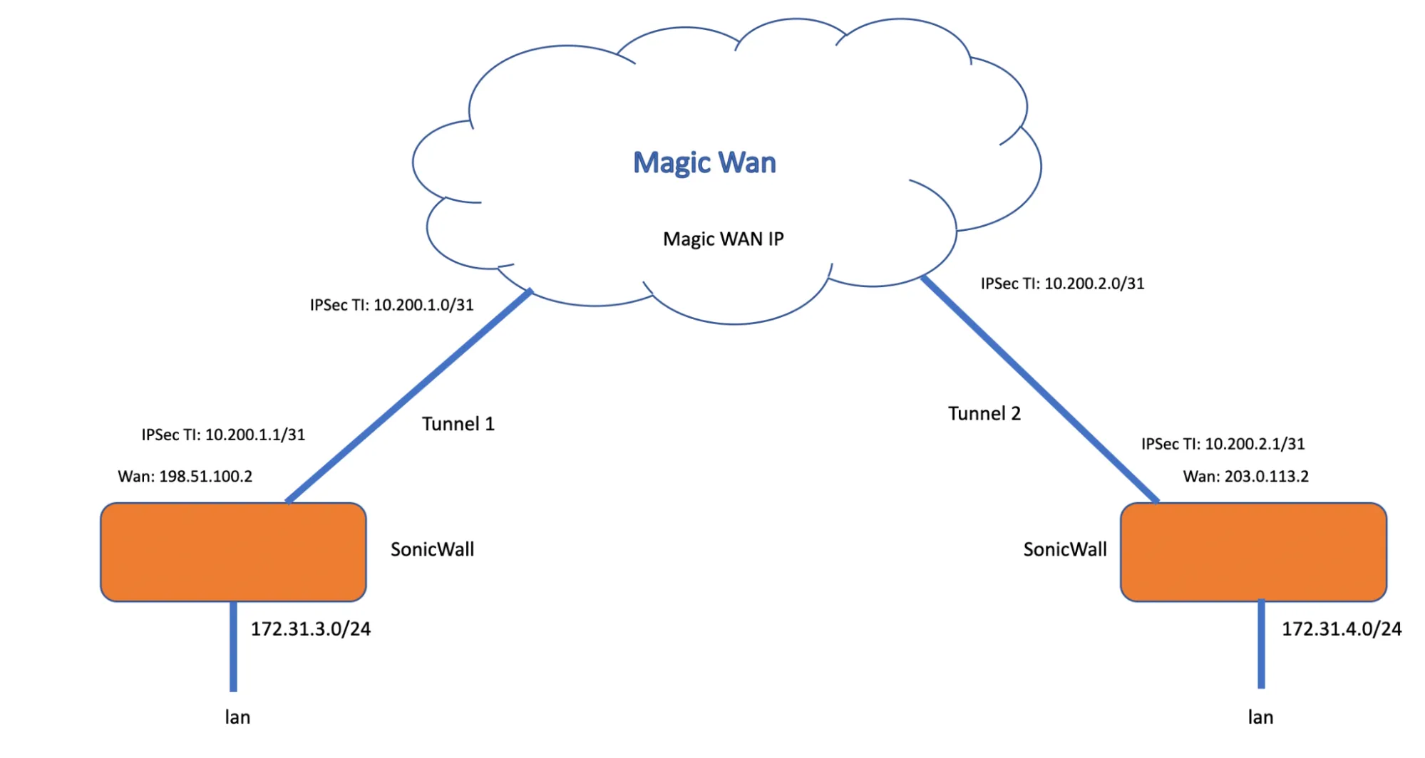
_Note: Labels in this image may reflect previous product names._
The following instructions show how to set up an IPsec connection on your SonicWall device. We will use the IP ranges from the above topology example to create the connections needed. Settings not explicitly mentioned can be left with their default values.
## 1\. Create an IPsec tunnel on your Cloudflare account
1. Start by [creating your IPsec tunnels](https://developers.cloudflare.com/cloudflare-wan/configuration/manually/how-to/configure-tunnel-endpoints/#add-tunnels) on Cloudflare. Name and describe the tunnels as needed, and add the following settings:
* **Interface address**: Enter the internal tunnel IP on the Cloudflare side of the IPsec tunnel. In this example, it is `10.200.1.0/31`.
* **Customer endpoint**: Enter the WAN IP address of your SonicWall device. In our example, this is `198.51.100.2`.
* **Cloudflare endpoint**: Enter one of the Cloudflare anycast IP addresses assigned to your account, available in [Leased IPs ↗](https://dash.cloudflare.com/?to=/:account/ip-addresses/address-space). In our example, this is `1.2.3.4`.
* **Pre-shared key**: Select **Use my own pre-shared key** and paste a secure key of your own.
2. Select **Add tunnels** when you are finished.
3. After you create your tunnel, Cloudflare dashboard will load a list of tunnels set up for your account. Select the arrow to expand the tunnels you have just created, and check the following settings:
* **Customer endpoint**: Refers to the SonicWall WAN IP that the VPN policy is bound to (in red).
* **Cloudflare endpoint**: Refers to the Cloudflare anycast IP address (in blue).
* **FQDN ID**: The ID used in the VPN policy for the SonicWall's Local IKE ID. Copy this ID and save it. You will need it when configuring the tunnel on your SonicWall (in green).
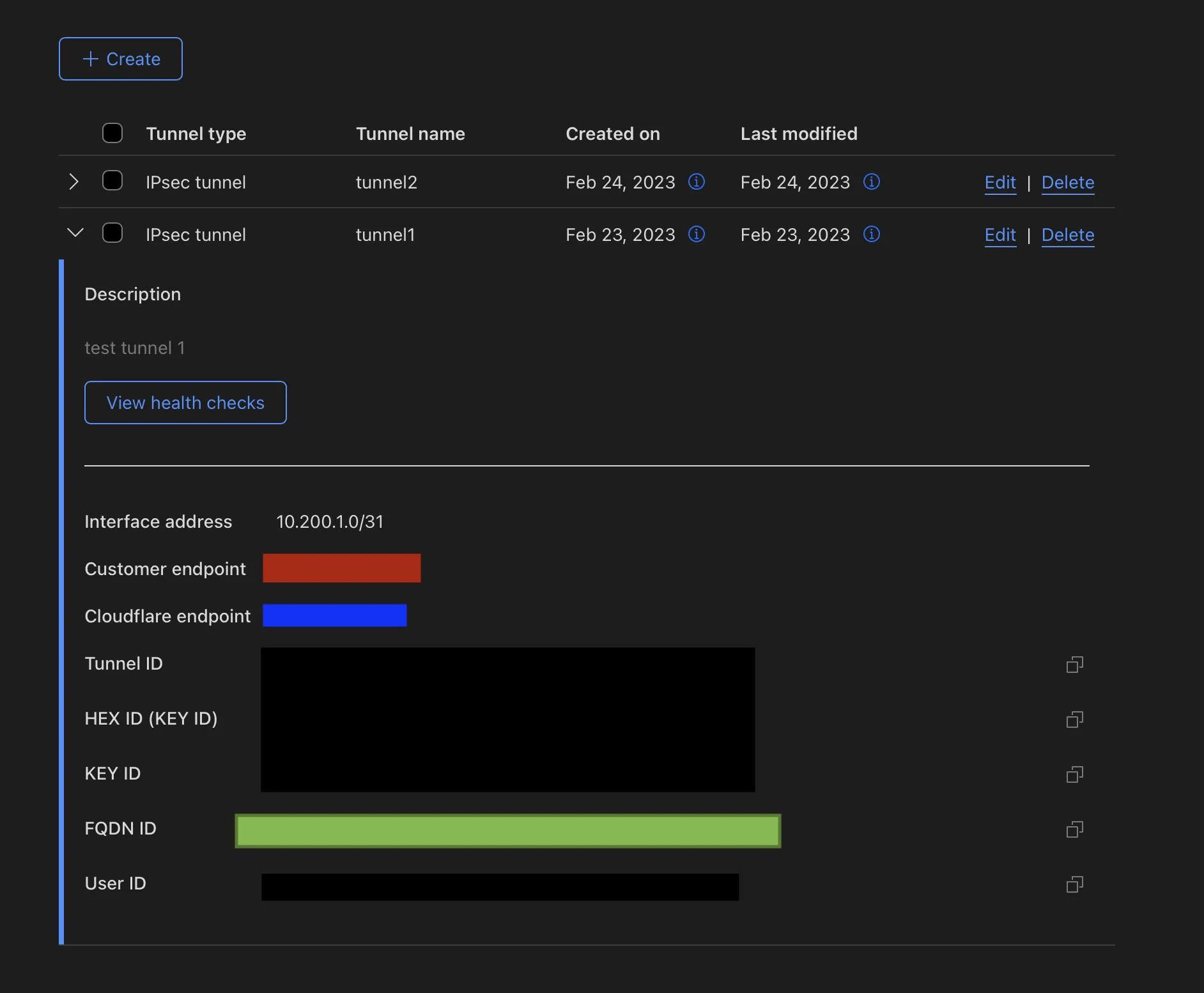
Note
The interface address on the Cloudflare side of the tunnel is `10.200.1.0/31`. You will need to use `10.200.1.1/31` on the SonicWall side of the tunnel.
## 2\. Create static routes on Cloudflare dashboard
Static routes are required for any networks that will be reached via the IPsec tunnel. In our example, there are two networks: `172.31.3.0/24` and the tunnel network `10.200.1.0/31`.
1. [Create your static routes](https://developers.cloudflare.com/cloudflare-wan/configuration/manually/how-to/configure-routes/#create-a-static-route). Name and describe them as needed, and add the following settings:
* **First tunnel**: Following our example, add `10.200.1.0/31` as the **Prefix** and `10.200.1.1` for the **Tunnel/Next hop**.
* **Second tunnel**: Following our example, add `172.31.3.0/24` as the **Prefix** and `10.200.1.1` for the **Tunnel/Next hop**.
2. Select **Add routes** when you are finished.
## 3\. Add a VPN configuration in SonicWall
1. Go to **Network** \> **IPsec VPN** \> **Rules and Settings**.
2. Select **Add**.
3. In **General** \> **Security Policy** group, add the following settings:
* **Authentication Method**: _IKE Using Preshared Secret_.
* **IPsec Primary Gateway Name or Address**: Enter Cloudflare's anycast IP address for the primary gateway (in blue).
4. In the **IKE Authentication** group, add the following settings:
* **Shared secret**: Paste the pre-shared key you use to create the IPsec tunnel in step 1 (in purple).
* **Local IKE ID**: Select _Domain name_ from the drop-down menu, and paste here the **FQDN ID** you saved from step 1, after creating the IPsec tunnel (in green).
* **Peer IKE IDE**: Select _IPv4_ Address from the drop-down menu, and enter the Cloudflare anycast IP address (in blue).
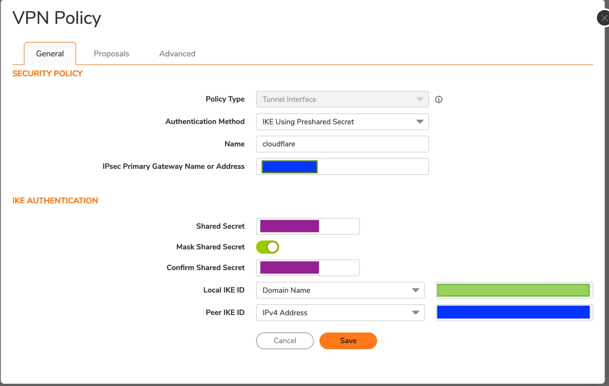
1. Select **Proposals**. VPN Policy is somewhat flexible. Adjust these settings to match your organization's preferred security policy. As an example, you can use the settings in the examples below.
2. In the **IKE (Phase 1) Proposal** group, select the following settings:
* **Exchange**: _IKEv2 Mode_
* **DH Group**: _Group 20_
* **Encryption**: _AES-256_
* **Authentication**: _SHA256_
* **Life Time (seconds)**: `86400`
3. In the **IPsec (Phase 2) Proposal** group, add the following settings:
* **Protocol**: _ESP_
* **Encryption**: _AESGCM16-256_
* **Authentication**: _None_
* **Enable Perfect Forward Secrecy**: Enabled
* **DH Group**: _Group 20_
* **Life Time (seconds)**: `28800`
4. Select **Advanced**.
5. Enable **Disable IPsec Anti-Replay**.
6. In **VPN Policy bound to** select your WAN interface from the drop-down menu, to bind it to your VPN.
7. Select **Save**.
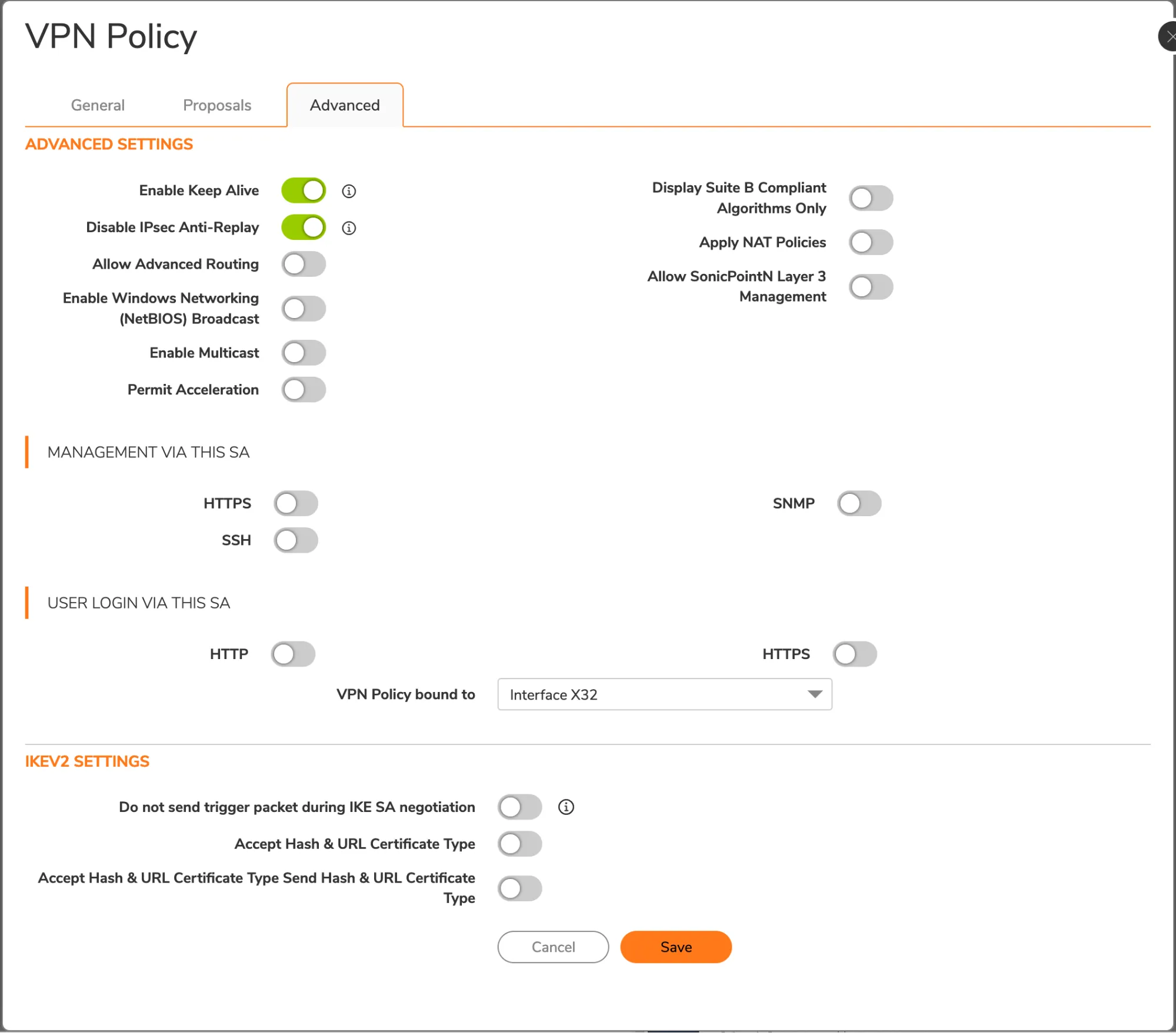
## 4\. Add a VPN tunnel interface
SonicOS requires a VPN tunnel interface to route traffic via Cloudflare WAN. When creating the interface, use the prefix `10.200.1.1/31`. This matches with the Cloudflare side for this tunnel, which is `10.200.1.0`.
Note
You will need to use a different IP pair for each tunnel/site.
1. Go to **Network** \> **System** \> **Interfaces**.
2. Select **Add interface** \> **VPN Tunnel Interface**.
3. For IP Address, use `10.200.1.1`.
4. Enable **Ping**. This is required so the interface can be pinged for debugging and Cloudflare WAN health checks.
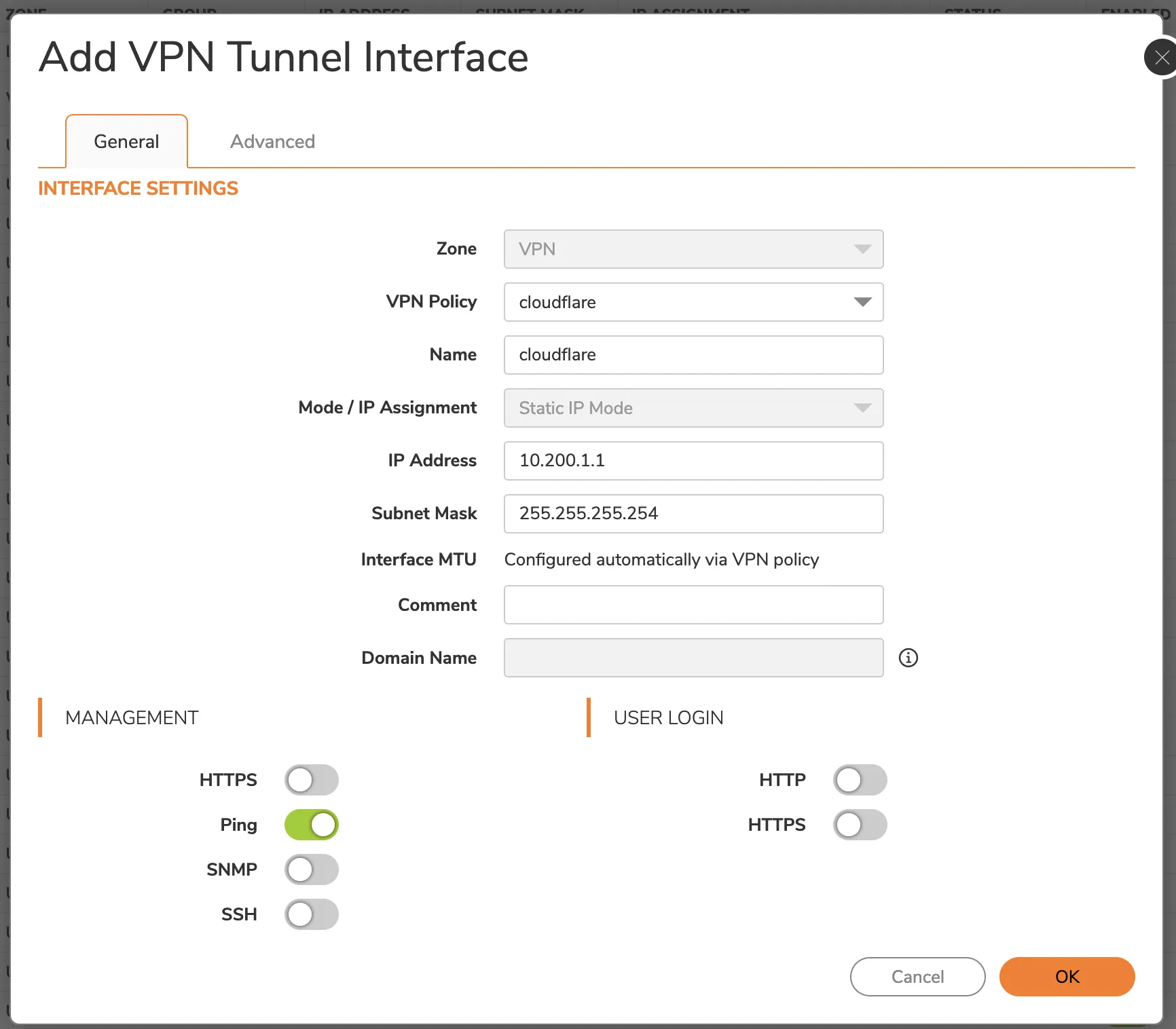
1. Select **Advanced**.
2. Enable the **Enable Asymmetric Route Support** option. This is required for the IPsec tunnel health check.
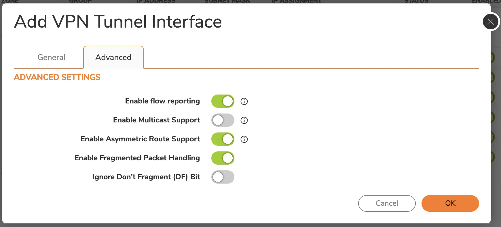
1. Select **OK**.
## 5\. Add address object(s)
Address objects are necessary for route policies. In our example, we have one other site that will be reached via Cloudflare WAN. First, you need to create address objects for each network. Then, you need to create an address group that contains all the remote networks. This address group will be used in the next step to create the correct route policies.
To add an address object:
1. Select **Object** \> **Match Objects** \> **Addresses**.
2. Select **Address Objects** \> **Add**.
3. Enter the information for your address object - refer to the topology image for the examples this tutorial is using. Since the addresses are in the VPN zone, set the **Zone Assignment** for the object to _VPN_.
4. Select **Save**. The window will stay on to facilitate multiple entries. Select **X** to close it.
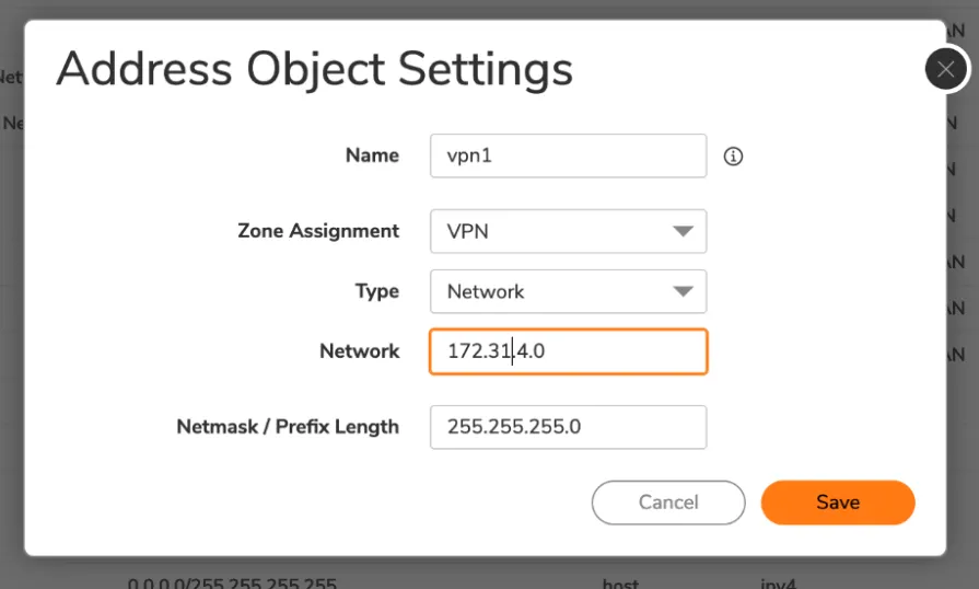
1. Select **Address Groups** \> **Add** to add a new address group.
2. Enter a **Name** for your address group.
3. Select the individual network objects you have created on the left menu, and add them to the group by selecting the right-facing arrow in the middle column.
4. Select **Save**.
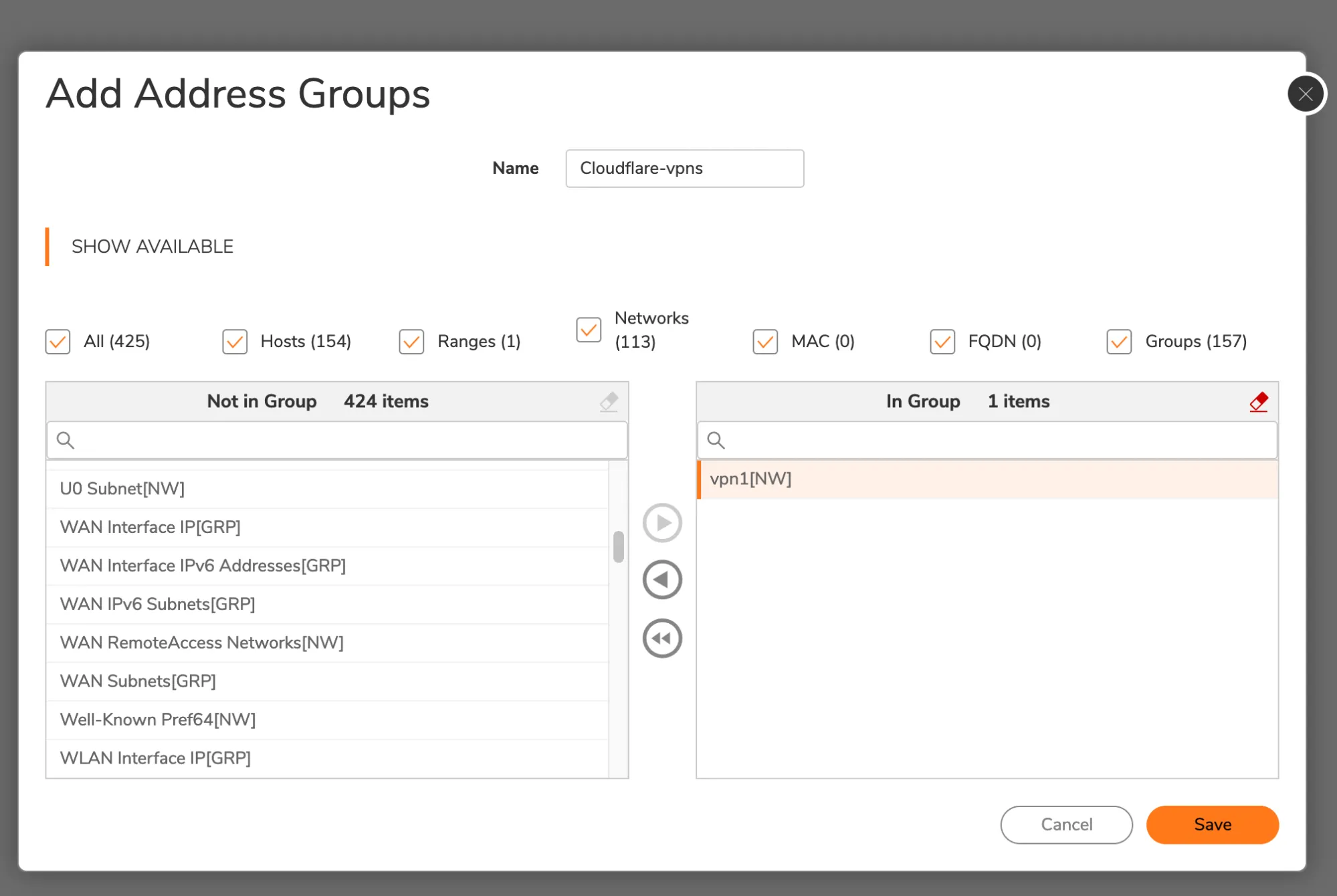
## 6\. Set up routing
Add a route using the address object or group just created as the destination.
1. Select **Policy** \> **Rules and Policies** \> **Routing Rules**.
2. Select **Add** to add your route policy.
3. The **Next Hop** should be the VPN tunnel interface that was previously created in the interface panel.
## 7\. Add access rule for health checks
An additional access rule is required for Cloudflare WAN health checks to work properly. This will enable the WAN IP to receive ICMP pings via the tunnel, and return them over the WAN.
1. Select **Policy** \> **Rules and Policies**.
2. Select **Access Rules** \> **Add**.
3. Enter a descriptive name for your policy.
4. In **Source / Destination** \> **Destination > Port/Services**, select _ICMP_ from the drop-down menu.
5. Select **Optional Settings**.
6. In **Others**, enable **Allow Management traffic**.
## 8\. Setup health checks
You have to [configure Cloudflare WAN health checks](https://developers.cloudflare.com/cloudflare-wan/configuration/manually/how-to/configure-tunnel-endpoints/#add-tunnels) correctly. Here is an example of how to set up health checks:
Terminal window
```
curl --request PUT \
https://api.cloudflare.com/client/v4/accounts/{account_id}/magic/ipsec_tunnels/{tunnel_id} \
--header "X-Auth-Email: " \
--header "X-Auth-Key: " \
--header "Content-Type: application/json" \
--data '{
"health_check": {
"direction": "bidirectional",
"enabled": true,
"type": "request",
"rate": "low"
}
}'
```
Health checks might take some time to stabilize after the configuration is changed.
## 9\. Verify tunnel status on Cloudflare dashboard
The Cloudflare dashboard monitors the health of all anycast tunnels on your account that route traffic from Cloudflare to your origin network. Refer to [Check tunnel health in the dashboard](https://developers.cloudflare.com/cloudflare-wan/configuration/common-settings/check-tunnel-health-dashboard/) for more information.
```json
{"@context":"https://schema.org","@type":"BreadcrumbList","itemListElement":[{"@type":"ListItem","position":1,"item":{"@id":"/directory/","name":"Directory"}},{"@type":"ListItem","position":2,"item":{"@id":"/cloudflare-wan/","name":"Cloudflare WAN"}},{"@type":"ListItem","position":3,"item":{"@id":"/cloudflare-wan/configuration/","name":"Configuration"}},{"@type":"ListItem","position":4,"item":{"@id":"/cloudflare-wan/configuration/manually/","name":"Manual configuration"}},{"@type":"ListItem","position":5,"item":{"@id":"/cloudflare-wan/configuration/manually/third-party/","name":"Third-party integration"}},{"@type":"ListItem","position":6,"item":{"@id":"/cloudflare-wan/configuration/manually/third-party/sonicwall/","name":"SonicWall"}}]}
```
---
---
title: Sophos Firewall
description: This tutorial shows you how to use Cloudflare WAN (formerly Magic WAN) with the following versions of the Sophos Firewall:
image: https://developers.cloudflare.com/zt-preview.png
---
[Skip to content](#%5Ftop)
Was this helpful?
YesNo
[ Edit page ](https://github.com/cloudflare/cloudflare-docs/edit/production/src/content/docs/cloudflare-wan/configuration/manually/third-party/sophos-firewall.mdx) [ Report issue ](https://github.com/cloudflare/cloudflare-docs/issues/new/choose)
Copy page
# Sophos Firewall
This tutorial shows you how to use Cloudflare WAN (formerly Magic WAN) with the following versions of the Sophos Firewall:
* **Sophos form factor tested:**
* Sophos Firewall XGS and XG series hardware
* Sophos Firewall virtual appliance on VMware
* **Sophos software versions tested:**
* SFOS Version 19.0 MR2-Build 472
* SFOS Version 19.5.1 MR1-Build 278
You can connect through [Generic Routing Encapsulation (GRE) or IPsec tunnels](https://developers.cloudflare.com/cloudflare-wan/configuration/manually/how-to/configure-tunnel-endpoints/) to Cloudflare WAN.
## IPsec connection
The following instructions show how to setup an IPsec connection on your Sophos Firewall device. Settings not explicitly mentioned can be left with their default values.
### 1\. Add an IPsec profile
1. Go to **System** \> **Profiles**.
2. In **IPsec profiles**, select **Add**.
3. In the **General settings** group, make sure you have the following settings:
* **Name**: Give your profile a descriptive name.
* **Key exchange**: **IKEv2**
* **Authentication mode**: **Main mode**
4. In the **Phase 1** group, make sure you have the following settings:
* **DH group (key group)**: _20_
* **Encryption**: _AES256_
* **Authentication**: _SHA2 256_
5. In the **Phase 2** group, select the following:
* **PFS group (DH group)**: _Same as phase-1_
* **Key life**: _28800_
* **Encryption**: _AES256_
* **Authentication**: _SHA2 256_
6. Enable **Dead Peer Detection**.
7. In **When peer unreachable**, select _Re-initiate_.
8. Select **Save**.
### 2\. Create IPsec connection tunnel
The next step involves configuring a site-to-site IPsec VPN connection on your Sophos Firewall device.
1. Go to **Configure** \> **Site-to-site VPN**.
2. In **IPsec**, select **Add**.
3. In the **General settings** group, make sure you have the following settings:
* **Name**: Give your site-to-site VPN a descriptive name.
* **Connection type**: _Tunnel interface_
* **Gateway type**: _Initiate the connection_
4. In the **Encryption** group, make sure you have the following settings:
* **Authentication type**: **Preshared key**
5. In **Gateway settings**, make sure you have the following settings:
* **Gateway address**: Enter one of the Cloudflare anycast IP addresses assigned to your account, available in [Leased IPs ↗](https://dash.cloudflare.com/?to=/:account/ip-addresses/address-space).
* **Local ID type**: Add the [IKE ID](https://developers.cloudflare.com/cloudflare-wan/reference/gre-ipsec-tunnels/#supported-ike-id-formats) provided by Cloudflare.
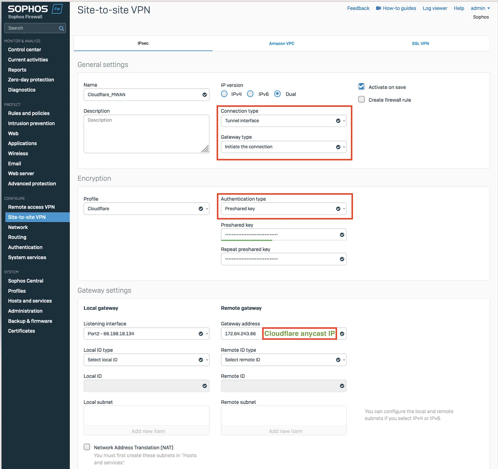
_Note: Labels in this image may reflect a previous product name._
After setting up your IPsec tunnel, it will show up on the IPsec connections list with an **Active** status.
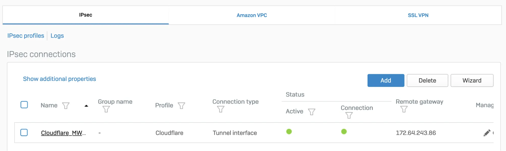
_Note: Labels in this image may reflect a previous product name._
### 3\. Assign the XFRM interface address
You must use an interface address from the `/31` subnet required to [configure tunnel endpoints](https://developers.cloudflare.com/cloudflare-wan/configuration/manually/how-to/configure-tunnel-endpoints/) on Cloudflare WAN.
1. Go to **Configure** \> **Network**.
2. In **Interfaces**, select the corresponding interface to the IPsec tunnel you created in [step 2](#2-create-ipsec-connection-tunnel).
3. Edit the interface to assign an address from the `/31` subnet required to [configure tunnel endpoints](https://developers.cloudflare.com/cloudflare-wan/configuration/manually/how-to/configure-tunnel-endpoints/). When you are finished, it should look similar to the following:
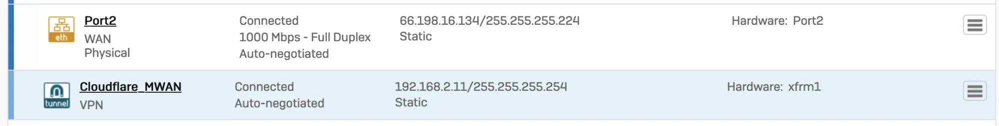
_Note: Labels in this image may reflect a previous product name._
### 4\. Add a firewall rule
1. Go to **Protect** \> **Rules and policies**.
2. In **Firewall rules**, create a firewall rule with the criteria and security policies from your company that allows traffic to flow between Sophos and Cloudflare WAN.
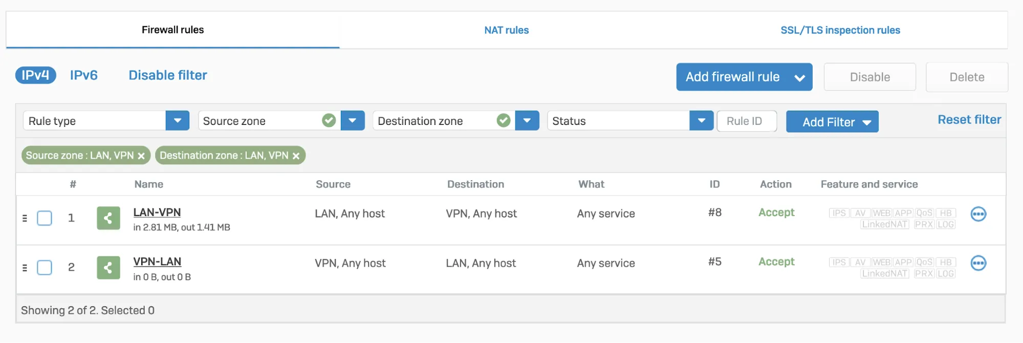
### 5\. Disable IPsec anti-replay
Disable IPsec Anti-Replay on your Sophos Firewall. Changing the anti-replay settings restarts the IPsec service, which causes tunnel-flap for all IPsec tunnels. This will also disable IPsec anti-replay protection for all VPN connections globally. Plan these changes accordingly.
Below are instructions on how to achieve this on SFOS version 19 and SFOS version 19.5:
#### SFOS 19.0 MR2-Build 472 or 19.5 MR1-Build278 or later versions:
1. Sign in to the CLI.
2. Enter **4** to choose **Device console**, and enter the following command:
Terminal window
```
set vpn ipsec-performance anti-replay window-size 0
```
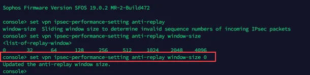
#### Older SFOS versions
Contact Sophos support.
## GRE connection
### 1\. Configure a GRE tunnel between SFOS and Cloudflare
Start by configuring a GRE tunnel between SFOS and the Cloudflare anycast IP address.
1. Sign in to the CLI.
2. Enter **4** to choose **Device console**, and enter the following command:
Terminal window
```
system gre tunnel add name local-gw remote-gw local-ip remote-ip
```
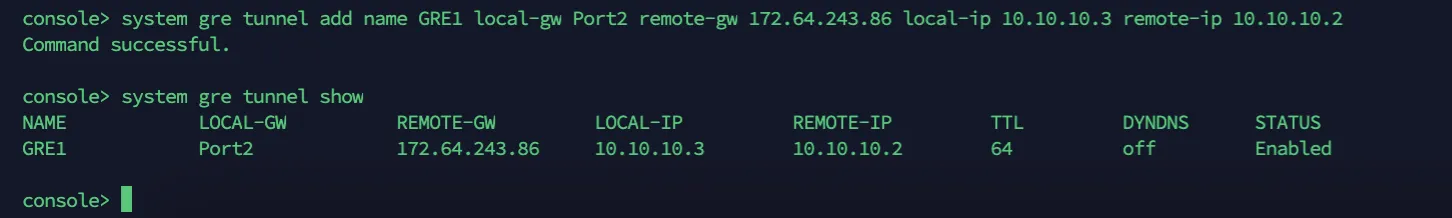
For more details, refer to the [Sophos Firewall knowledge base ↗](https://support.sophos.com/support/s/article/KB-000035813?language=en%5FUS).
### 2\. Add a GRE or SD-WAN route to redirect traffic through the GRE tunnel
Refer to [Traffic redirection mechanism on Sophos Firewall](#traffic-redirection-mechanism-on-sophos-firewall) for information on how to add a GRE or SD-WAN route to redirect traffic through the GRE tunnel.
### 3\. Add a firewall rule for LAN/DMZ to VPN
Create a firewall rule with the criteria and security policies from your company that allows traffic to flow between Sophos and Cloudflare WAN. This firewall rule should include the required networks and services.
1. Go to **Protect** \> **Rules and policies**.
2. In **Firewall rules**, select **IPv4** \> **Add firewall rule**.

## Traffic redirection mechanism on Sophos Firewall
To redirect traffic, you can add a static or an SD-WAN route.
### IPsec
#### Static route
Go to **Configure** \> **Routing** \> **Static routes** to add an XFRM interface-based route. The interface will be automatically created when you set up a tunnel interface based on IPsec (such as the Cloudflare\_MWAN example from above).
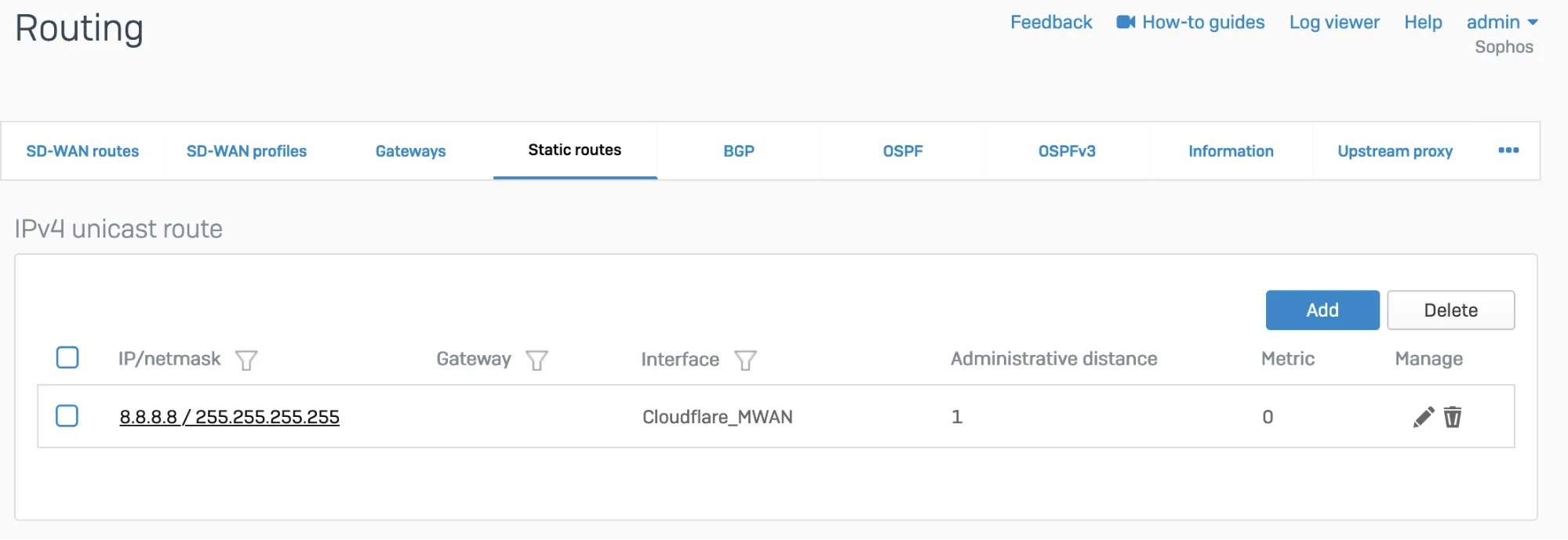
_Note: Labels in this image may reflect a previous product name._
#### SD-WAN route
1. Go to **Configure** \> **Routing** \> **Gateways** to create a custom gateway on the XFRM interface. The interface will be automatically created when you set up a tunnel interface based on IPsec (such as the Cloudflare\_MWAN example from above).
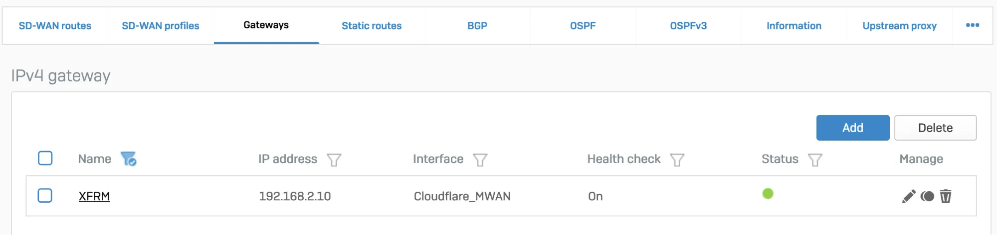
_Note: Labels in this image may reflect a previous product name._
1. In **Configure** \> **Routing** \> **SD-WAN routes**, select **Add** to add the desired networks and services in the route to redirect traffic to Cloudflare. Enter a descriptive name for your connection, and the IP addresses you set up for your IPsec tunnels in **Incoming interface** and **Source networks**. Do not forget to choose the correct **Primary gateway** option.
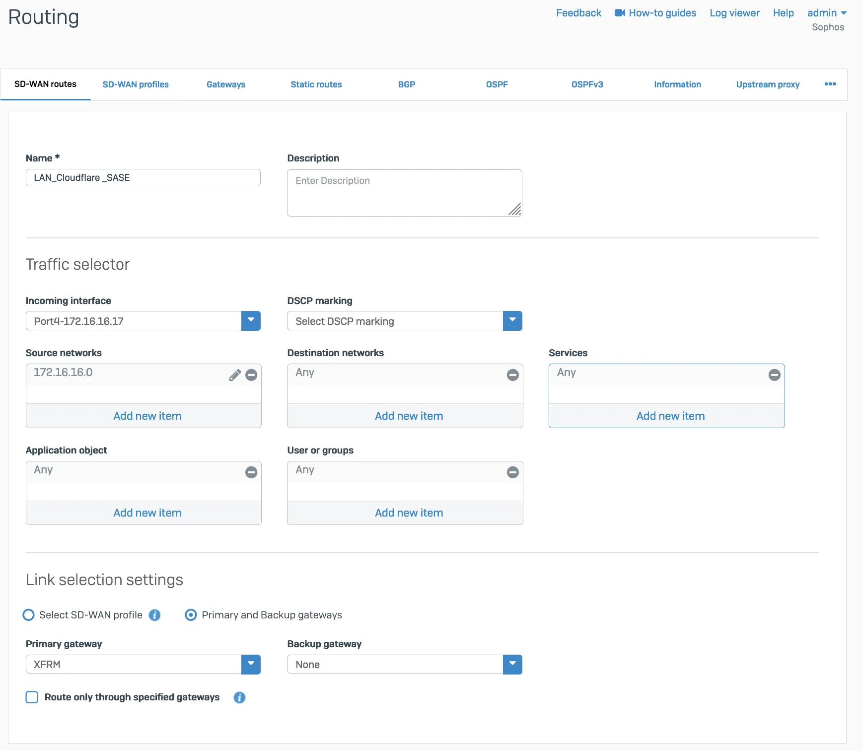
### GRE
Add a GRE route, an SD-WAN route, or both depending on your routing requirements.
#### GRE route
Add the route on the CLI.
1. Sign in to the CLI.
2. Enter **4** to choose **Device console**, and enter the following command to create the tunnel:
Terminal window
```
system gre route add net tunnelname
```
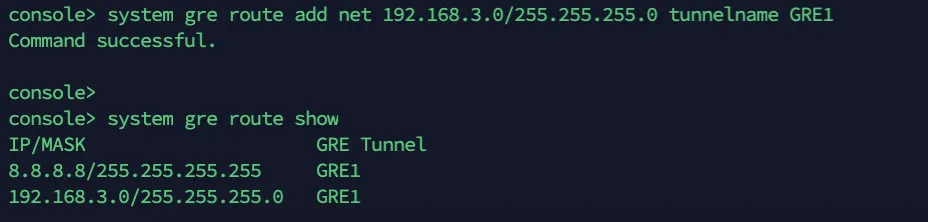
#### SD-WAN route
1. Add a custom gateway on GRE with the peer IP address (from the `/31` subnet you chose earlier) as the Gateway IP address, and disable **Health check**.
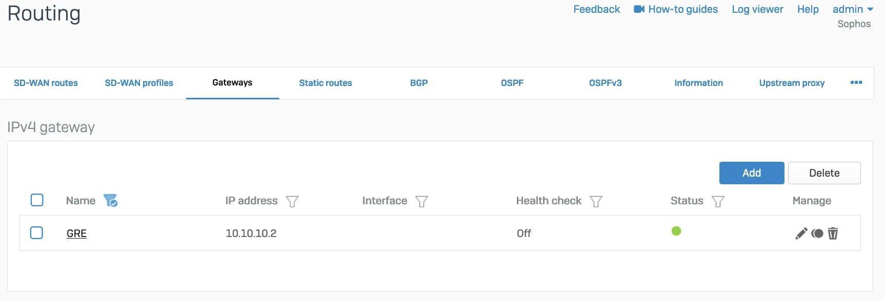
1. Add an SD-WAN route with the desired networks and services in the route to redirect traffic to Cloudflare.

## Verify tunnel status on Cloudflare dashboard
The Cloudflare dashboard monitors the health of all anycast tunnels on your account that route traffic from Cloudflare to your origin network. Refer to [Check tunnel health in the dashboard](https://developers.cloudflare.com/cloudflare-wan/configuration/common-settings/check-tunnel-health-dashboard/) for more information.
### Configure Cloudflare health checks
1. The ICMP probe packet from Cloudflare must be the type ICMP request, with anycast source IP. In the following example, we have used `172.64.240.252` as a target example:
Terminal window
```
curl --request PUT \
https://api.cloudflare.com/client/v4/accounts/{account_id}/magic/ipsec_tunnels/{tunnel_id} \
--header "X-Auth-Email: " \
--header "X-Auth-Key: " \
--header "Content-Type: application/json" \
--data '{
"health_check": {
"enabled": true,
"target": "172.64.240.252",
"type": "request",
"rate": "mid"
}
}'
```
1. Go to **Configure** \> **Network** \> **Interfaces** \> **Add alias**. Add the IP address provided by Cloudflare for the ICMP probe traffic. This is needed to prevent Sophos firewall from dropping them as spoof packets. This is not the same IP used to create VPN. This is the special IP address for probe traffic only.

1. ICMP reply from SFOS should go back via the same tunnel on which the probe packets are received. You will need to create an additional SD-WAN policy route.
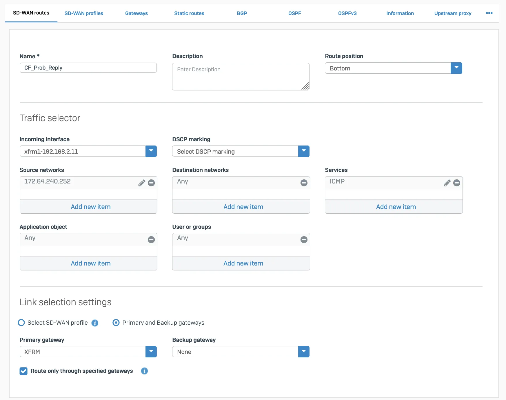
Packet flow will look like the following:
Terminal window
```
tcpdump -nn proto 1
```
```
tcpdump: verbose output suppressed, use -v or -vv for full protocol decode
listening on any, link-type LINUX_SLL (Linux cooked v1), capture size 262144 bytes
13:09:55.500453 xfrm1, IN: IP 172.70.51.31 > 172.64.240.252: ICMP echo request, id 33504, seq 0, length 64
13:09:55.500480 xfrm1, OUT: IP 172.64.240.252 > 172.70.51.31: ICMP echo reply, id 33504, seq 0, length 64
13:09:55.504669 xfrm1, IN: IP 172.71.29.66 > 172.64.240.252: ICMP echo request, id 60828, seq 0, length 64
13:09:55.504695 xfrm1, OUT: IP 172.64.240.252 > 172.71.29.66: ICMP echo reply, id 60828, seq 0, length 64
```
## Verify tunnel status on Sophos Firewall dashboard
### IPsec
When the tunnel is working, its **Status** will be green.

_Note: Labels in this image may reflect a previous product name._
The corresponding XFRM interface will also show a **Connected** status.

_Note: Labels in this image may reflect a previous product name._
### GRE
Access the CLI and type `system gre tunnel show` to check the status of a GRE tunnel. When the tunnel is working, its status will show up as **Enabled**.
 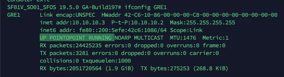
## Troubleshooting
If a tunnel shows a connected status at both ends, but is not established:
* Check if the IPsec profile configuration is correct.
* Make sure the corresponding tunnel interfaces are up.
* Make sure routing configuration and route precedence are correctly set on SFOS.
* Make sure a static back route is added on Cloudflare.
* Firewall rules for specific zones and host or service must be added in SFOS. GRE and IPsec belong to the VPN zone.
* Perform `tcpdump` to check if packets are going through the VPN or GRE tunnel as expected.
* Perform a packet capture on Cloudflare to see if traffic is reaching the Cloudflare platform.
```json
{"@context":"https://schema.org","@type":"BreadcrumbList","itemListElement":[{"@type":"ListItem","position":1,"item":{"@id":"/directory/","name":"Directory"}},{"@type":"ListItem","position":2,"item":{"@id":"/cloudflare-wan/","name":"Cloudflare WAN"}},{"@type":"ListItem","position":3,"item":{"@id":"/cloudflare-wan/configuration/","name":"Configuration"}},{"@type":"ListItem","position":4,"item":{"@id":"/cloudflare-wan/configuration/manually/","name":"Manual configuration"}},{"@type":"ListItem","position":5,"item":{"@id":"/cloudflare-wan/configuration/manually/third-party/","name":"Third-party integration"}},{"@type":"ListItem","position":6,"item":{"@id":"/cloudflare-wan/configuration/manually/third-party/sophos-firewall/","name":"Sophos Firewall"}}]}
```
---
---
title: strongSwan
description: This tutorial explains how to set up strongSwan along with Cloudflare WAN (formerly Magic WAN). You will learn how to configure strongSwan, configure an IPsec tunnel, and create Policy-Based Routing (PBR).
image: https://developers.cloudflare.com/zt-preview.png
---
[Skip to content](#%5Ftop)
Was this helpful?
YesNo
[ Edit page ](https://github.com/cloudflare/cloudflare-docs/edit/production/src/content/docs/cloudflare-wan/configuration/manually/third-party/strongswan.mdx) [ Report issue ](https://github.com/cloudflare/cloudflare-docs/issues/new/choose)
Copy page
# strongSwan
This tutorial explains how to set up strongSwan along with Cloudflare WAN (formerly Magic WAN). You will learn how to configure strongSwan, configure an IPsec tunnel, and create Policy-Based Routing (PBR).
## 1\. Configure health checks
Configure the [bidirectional health checks](https://developers.cloudflare.com/cloudflare-wan/configuration/manually/how-to/configure-tunnel-endpoints/#add-tunnels) target for Cloudflare WAN. For this tutorial, use `172.64.240.252` as the target IP address, and `type` as the request.
This can be set up [with the API](https://developers.cloudflare.com/api/resources/magic%5Ftransit/subresources/ipsec%5Ftunnels/methods/update/). For example:
Terminal window
```
curl --request PUT \
https://api.cloudflare.com/client/v4/accounts/{account_id}/magic/ipsec_tunnels/{tunnel_id} \
--header "X-Auth-Email: " \
--header "X-Auth-Key: " \
--header "Content-Type: application/json" \
--data '{
"health_check": {
"enabled": true,
"target": "172.64.240.252",
"type": "request",
"rate": "mid"
}
}'
```
## 2\. Configure strongSwan
1. [Install strongSwan ↗](https://docs.strongswan.org/docs/5.9/install/install.html). For example, open the console and run:
Terminal window
```
sudo apt-get install strongswan -y
```
1. Open `/etc/strongswan.conf` and add the following settings:
```
charon {
load_modular = yes
install_routes = no
install_virtual_ip = no
plugins {
include strongswan.d/charon/*.conf
}
}
include strongswan.d/*.conf
```
## 3\. Configure the IPsec file
1. Open `/etc/ipsec.conf` and add the following settings:
```
# ipsec.conf - strongSwan IPsec configuration file
config setup
charondebug="all"
uniqueids = yes
conn %default
ikelifetime=24h
rekey=yes
reauth=no
keyexchange=ikev2
authby=secret
dpdaction=restart
closeaction=restart
# Sample VPN connections
conn cloudflare-ipsec
auto=start
type=tunnel
fragmentation=no
leftauth=psk
# Private IP of the VM
left=%any
# Tunnel ID from dashboard, in this example FQDN is used
leftid=..ipsec.cloudflare.com
leftsubnet=0.0.0.0/0
# Cloudflare Anycast IP
right=
rightid=
rightsubnet=0.0.0.0/0
rightauth=psk
ike=aes256-sha256-ecp384!
esp=aes256-sha256-ecp384!
replay_window=0
mark_in=42
mark_out=42
leftupdown=/etc/strongswan.d/ipsec-vti.sh
```
1. Create a virtual tunnel interface (VTI) with the IP configured as the target for Cloudflare's health checks (`172.64.240.252`) to route IPsec packets. Open `/etc/strongswan.d/`.
2. Create a script called `ipsec-vti.sh` and add the following:
```
#!/bin/bash
set -o nounset
set -o errexit
VTI_IF="vti0"
case "${PLUTO_VERB}" in
up-client)
ip tunnel add "${VTI_IF}" local "${PLUTO_ME}" remote "${PLUTO_PEER}" mode vti \
key "${PLUTO_MARK_OUT%%/*}"
ip link set "${VTI_IF}" up
ip addr add 172.64.240.252/32 dev vti0
sysctl -w "net.ipv4.conf.${VTI_IF}.disable_policy=1"
sysctl -w "net.ipv4.conf.${VTI_IF}.rp_filter=0"
sysctl -w "net.ipv4.conf.all.rp_filter=0"
ip rule add from 172.64.240.252 lookup viatunicmp
ip route add default dev vti0 table viatunicmp
;;
down-client)
ip tunnel del "${VTI_IF}"
ip rule del from 172.64.240.252 lookup viatunicmp
ip route del default dev vti0 table viatunicmp
;;
esac
echo "executed"
```
## 4\. Add policy-based routing
Create Policy-Based Routing (PBR) to redirect returning traffic through the IPsec tunnel. Without it, the ICMP replies to the health probes sent by Cloudflare will be returned through the Internet, instead of the same IPsec tunnel.
This tutorial uses [iproute2 ↗](https://en.wikipedia.org/wiki/Iproute2) to route IP packets from `172.64.240.252` to the tunnel interface.
1. Open `/etc/iproute2/`.
2. Edit the `rt_tables` file to add a routing table number and name. In this example, use `viatunicmp` as the name and `200` as the number for the routing table.
```
#
# reserved values
#
255 local
254 main
253 default
0 unspec
200 viatunicmp
#
# local
#
#1 inr.ruhep
```
1. Add a rule to match the routing table. This rule instructs the system to use routing table `viatunicmp` if the packet's source address is `172.64.240.252`:
Terminal window
```
ip rule add from 172.64.240.252 lookup viatunicmp
```
1. Add a route to the `viatunicmp` routing table. This is the default route through the interface `vti0` in the `viatunicmp` table.
Terminal window
```
ip route add default dev vti0 table viatunicmp
```
1. Start IPsec. You can also `stop`, `restart`, and show the `status` for the IPsec connection:
Terminal window
```
ipsec start
```
```
Security Associations (1 up, 0 connecting):
cloudflare-ipsec[1]: ESTABLISHED 96 minutes ago, .ipsec.cloudflare.com]...162.159.67.88[162.159.67.88]
cloudflare-ipsec{4}: INSTALLED, TUNNEL, reqid 1, ESP SPIs: c4e20a95_i c5373d00_o
cloudflare-ipsec{4}: 0.0.0.0/0 === 0.0.0.0/0
```
## 5\. Check connection status
Use tcpdump to investigate the status of health checks originated from Cloudflare.
Terminal window
```
sudo tcpdump -i esp and host
```
In this example, the outgoing Internet interface shows that the IPsec encrypted packets (ESP) from Cloudflare's health check probes (both the request and response) are going through the IPsec tunnel.
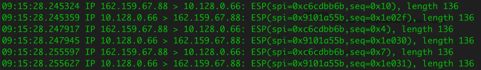
Run tcpdump on `vti0` to check the decrypted packets.
Terminal window
```
sudo tcpdump -i vti0 host 172.64.240.252
```
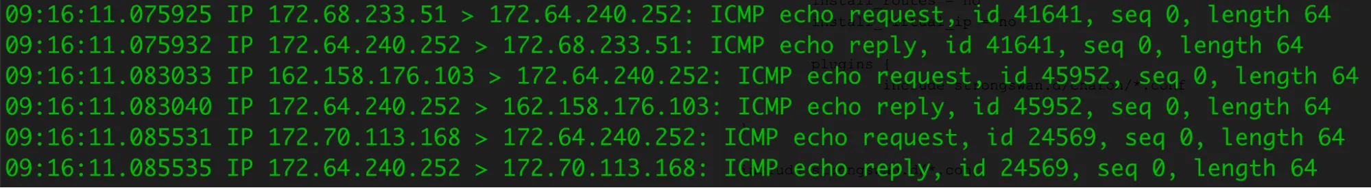
```json
{"@context":"https://schema.org","@type":"BreadcrumbList","itemListElement":[{"@type":"ListItem","position":1,"item":{"@id":"/directory/","name":"Directory"}},{"@type":"ListItem","position":2,"item":{"@id":"/cloudflare-wan/","name":"Cloudflare WAN"}},{"@type":"ListItem","position":3,"item":{"@id":"/cloudflare-wan/configuration/","name":"Configuration"}},{"@type":"ListItem","position":4,"item":{"@id":"/cloudflare-wan/configuration/manually/","name":"Manual configuration"}},{"@type":"ListItem","position":5,"item":{"@id":"/cloudflare-wan/configuration/manually/third-party/","name":"Third-party integration"}},{"@type":"ListItem","position":6,"item":{"@id":"/cloudflare-wan/configuration/manually/third-party/strongswan/","name":"strongSwan"}}]}
```
---
---
title: Ubiquiti
description: Connect a Ubiquiti UniFi Gateway to Cloudflare's network using Cloudflare WAN (formerly Magic WAN). These steps use the Cloud Gateway Max (UCG-Max) but work with other UniFi gateways supporting route-based IPsec (Internet Protocol Security) VPNs (Virtual Private Networks), like the Dream Machine series.
image: https://developers.cloudflare.com/zt-preview.png
---
[Skip to content](#%5Ftop)
Was this helpful?
YesNo
[ Edit page ](https://github.com/cloudflare/cloudflare-docs/edit/production/src/content/docs/cloudflare-wan/configuration/manually/third-party/ubiquiti.mdx) [ Report issue ](https://github.com/cloudflare/cloudflare-docs/issues/new/choose)
Copy page
# Ubiquiti
Connect a Ubiquiti UniFi Gateway to Cloudflare's network using Cloudflare WAN (formerly Magic WAN). These steps use the Cloud Gateway Max (UCG-Max) but work with other UniFi gateways supporting route-based IPsec (Internet Protocol Security) VPNs (Virtual Private Networks), like the Dream Machine series.
## Prerequisites
* Cloudflare account with Cloudflare WAN enabled (contact your account team)
* UniFi Cloud Gateway or Dream Machine with IPsec support
* UniFi Network Application (self-hosted or cloud)
* Static public IP from your ISP
* Admin access to both Cloudflare and UniFi
* Gather a **Magic Anycast IPv4** address from the **Leased IPs** section in the dashboard
* [ Go to **Address space** ](https://dash.cloudflare.com/?to=/:account/ip-addresses/address-space)
* Contact your account team if you do not see any IP addresses listed.
## 1\. Configure Cloudflare WAN
1. Refer to [Add tunnels](https://developers.cloudflare.com/cloudflare-wan/configuration/manually/how-to/configure-tunnel-endpoints/#add-tunnels) to learn how to add IPsec tunnels.
1. Select **IPsec tunnel** \> **Next**, and fill in the following settings:
* **Name**: `unifi-gw-primary`
* **IPv4 Interface Address**: `10.252.2.28/31` or refer to the [Tunnel endpoints documentation](https://developers.cloudflare.com/cloudflare-wan/configuration/manually/how-to/configure-tunnel-endpoints/)
* **Customer Endpoint**: This should be your UniFi Gateway's WAN IP (for example, `203.0.113.10`)
* **Cloudflare Endpoint**: This should be one of the IPv4 addresses gathered from Leased IPs.
* Under **Tunnel Health checks**, select:
* **Health check rate**: Set to desired level
* **Health check type**: _Request_
* **Health check direction**: _Bidirectional_
* **Health check target**: _Default_
* Under **Pre-shared key**:
* Select **Add pre-shared key later**. This key will be given during the UniFi site-to-site VPN configuration.
## 2\. Configure site-to-site VPN on UniFi
1. In UniFi Network, go to **Settings** \> **VPN** \> **Site-to-Site VPN**.
2. Select **Create New**.
3. Configure the following settings:
* **VPN Type:** `IPsec`.
* **Name:** `Cloudflare-Magic-WAN`.
* **Pre-shared key:** Copy this key. You need it for the IPsec tunnel.
* **Local IP:** Select the WAN interface (for example, `WAN1`).
* **Remote IP:** Enter the Cloudflare endpoint IP from [Step 1](#1-configure-cloudflare-wan).
* **VPN Method:** Route Based.
* **Tunnel IP:** `10.252.2.29/31` or refer to the [Tunnel endpoints documentation](https://developers.cloudflare.com/cloudflare-wan/configuration/manually/how-to/configure-tunnel-endpoints/).
* **Remote Networks:** Inside Cloudflare tunnel address (for example, `10.252.2.28/31`) and other remote subnets to access through Cloudflare WAN.
4. Set Advanced settings:
* **Key Exchange Version**: IKEv2.
* **IKE Encryption**: AES-256.
* **IKE Hash**: SHA256.
* **IKE DH Group**: 14.
* **IKE Lifetime**: 28800.
* **ESP Encryption**: AES-256.
* **ESP Hash**: SHA256.
* **ESP DH Group**: 14.
* **ESP Lifetime**: 28800.
* **PFS**: Enabled.
* **Local Authentication ID**: Auto.
* **Remote Authentication ID**: Uncheck **Auto**, and enter the Cloudflare Endpoint IP from [Step 1](#1-configure-cloudflare-wan).
* **MTU**: 1436.
5. Select **Apply**
## 3\. Add pre-shared key to Cloudflare
1. Go to the **Connectors** page.
[ Go to **Connectors** ](https://dash.cloudflare.com/?to=/:account/magic-networks/connections)
1. In the **IPsec/GRE tunnels** tab, find the IPsec tunnel you have just created.
1. Select your tunnel and then **Edit**.
2. Paste the preshared key from [Step 2](#2-configure-site-to-site-vpn-on-unifi).
3. Select **Save**.
## 4\. Configure Routes
1. Go to the **Routes** page.
[ Go to **Routes** ](https://dash.cloudflare.com/?to=/:account/magic-networks/routes)
1. Select **Create static route**.
1. Enter the following settings:
* **Prefix**: Your local network (for example, `192.168.1.0/24`).
* **Tunnel/Next hop**: Select your tunnel.
* **Priority**: `100`.
2. Select **Add routes** to add your static route.
## Verify connections
Wait a few minutes, then access both Cloudflare and UniFi to verify the tunnel's status:
Cloudflare
1. Go to Cloudflare WAN's **Network Health** page.
[ Go to **Network health** ](https://dash.cloudflare.com/?to=/:account/networking-insights/health)
1. Go to the **Connector health** tab.
2. Find the tunnel you have just created and make sure its status shows **Up**. Refer to [Check tunnel health in the dashboard](https://developers.cloudflare.com/cloudflare-wan/configuration/common-settings/check-tunnel-health-dashboard/) for more information.
UniFi
Go to **Settings** \> **VPN**, and make sure the status is **Connected**.
## Troubleshooting
**Tunnel down:**
* Verify Peer IP, pre-shared key, and IPsec settings match on both sides
* Check that the ISP is not blocking UDP ports `500`/`4500`
**Traffic not routing:**
* Verify Remote Subnets setting in UniFi VPN configuration
* Check firewall rules are not blocking VPN traffic
**Health check fails:**
* Allow ICMP from Cloudflare to the customer-side tunnel IP
* Target should be the `/31` interface IP, not your LAN gateway
## Policy-based routing
To route only specific devices through Cloudflare (UniFi Network Application):
1. Remove unnecessary routes from Remote Subnets in your VPN configuration.
2. Go to **Settings** \> **Policy Table**.
3. Under **Policy Engine** select **Create New Policy** with the following settings:
* Select `Route`.
* **Name**: Provide a name for the policy.
* **Type**: _Policy-Based_.
* **Interface/VPN Tunnel**: Select the VPN Tunnel (for example, `Cloudflare-Magic-WAN`).
* **Kill Switch**: _Enabled_ (recommended).
* **Source**: Select `Device/Network` and then choose the Device(s) or Network(s).
* **Destination**: _Any_.
* **Interface**: Your VPN tunnel.
## Next Steps
* Use [Cloudflare Network Firewall](https://developers.cloudflare.com/cloudflare-network-firewall/) for network policies.
* Configure a second tunnel for redundancy.
* Monitor traffic in the Cloudflare WAN dashboard.
---
You are now routing traffic through Cloudflare's network using Cloudflare WAN.
```json
{"@context":"https://schema.org","@type":"BreadcrumbList","itemListElement":[{"@type":"ListItem","position":1,"item":{"@id":"/directory/","name":"Directory"}},{"@type":"ListItem","position":2,"item":{"@id":"/cloudflare-wan/","name":"Cloudflare WAN"}},{"@type":"ListItem","position":3,"item":{"@id":"/cloudflare-wan/configuration/","name":"Configuration"}},{"@type":"ListItem","position":4,"item":{"@id":"/cloudflare-wan/configuration/manually/","name":"Manual configuration"}},{"@type":"ListItem","position":5,"item":{"@id":"/cloudflare-wan/configuration/manually/third-party/","name":"Third-party integration"}},{"@type":"ListItem","position":6,"item":{"@id":"/cloudflare-wan/configuration/manually/third-party/ubiquiti/","name":"Ubiquiti"}}]}
```
---
---
title: Velocloud
description: This document is intended to provide Arista VeloCloud customers with the steps to provision non SD-WAN destinations through Edge for connectivity with Cloudflare WAN (formerly Magic WAN).
image: https://developers.cloudflare.com/zt-preview.png
---
[Skip to content](#%5Ftop)
Was this helpful?
YesNo
[ Edit page ](https://github.com/cloudflare/cloudflare-docs/edit/production/src/content/docs/cloudflare-wan/configuration/manually/third-party/velocloud.mdx) [ Report issue ](https://github.com/cloudflare/cloudflare-docs/issues/new/choose)
Copy page
# Velocloud
This document is intended to provide Arista VeloCloud customers with the steps to provision non SD-WAN destinations through Edge for connectivity with Cloudflare WAN (formerly Magic WAN).
## VeloCloud Edge Nodes profile configuration
1. Log into VeloCloud Orchestrator and go to **Configure** \> **Profiles**.
2. Select **New profile** to create a new profile (for example, `vc-edge-03-profile`).
3. Select the **Device** tab and expand the **Interfaces** section.
4. Select the **Edge Model** corresponding to the device (Virtual Edge). The default interface scheme for the Virtual Edge will be displayed. For example: eight interfaces, from GE1 to GE8.
5. You are only using interfaces **GE3** and **GE4.** Disable all unused interfaces to ensure anyone with physical access to the edge node cannot connect any unused interfaces. Do this by selecting each interface one at a time and unchecking **Interface Enabled** followed by **Save**.
### Configure interfaces
This documentation assumes:
* **GE3**: WAN Interface (Static IP)
* **GE4**: LAN Interface (Static IP)
### Interface GE3 - WAN interface
Configure interface GE3 with the following settings:
* **Interface enabled**: Enabled
* **Capability**: Routed
* **Segments**: All Segments
* **Radius Authentication**: Not applicable
* **ICMP Echo Response**: Enabled
* **Underlay Accounting**: Enabled
* **Enable WAN Link**: Enabled
* **Edge to Edge Encryption**: Enabled
* **DNS Proxy**: Disabled
* **VLAN**: Unspecified (this example assumes the device is connected to an access-layer switch port)
* **EVDSL Modem Attached**: Disabled
#### IPv4 settings
* **Addressing Type**: Static
* **WAN Link**: User Defined
* **OSPF**: Not applicable
* **Multicast**: Not applicable
* **Advertise**: Disabled
* **NAT Direct Traffic**: Enabled
* **Trusted Source**: Disabled
* **Reverse Path Forwarding**: (unspecified)
#### IPv6 settings
IPv6 is currently not supported with Cloudflare WAN. Uncheck the **Enabled** checkbox.
**Router Advertisement Host Settings**
* Disabled
**L2 Settings**
* **Autonegotiate**: Enabled
* **MTU**: 1500
Select **Save** to apply changes for Interface **GE3**.
### Interface GE4 - LAN Interface
* **Interface Enabled**: Enabled
* **Capability**: Routed
* **Segments**: Global Segment
* **Radius Authentication**: Disabled (Not applicable)
* **ICMP Echo Response**: Enabled
* **Underlay Accounting**: Enabled
* **WAN Link**: Disabled
* **Edge To Edge Encryption**: Enabled
* **DNS Proxy**: Disabled
* **VLAN**: Unspecified (this example assumes the device is connected to an access-layer switch port)
* **EVDSL Modem Attached**: Disabled
#### IPv4 Settings
* **Addressing Type**: DHCP or Static (example assumes Static IP)
* **WAN Link**: User Defined
* **OSPF**: Not applicable
* **Multicast**: Not applicable
* **Advertise**: Disabled
* **NAT Direct Traffic**: Enabled
* **Trusted Source**: Disabled
* **Reverse Path Forwarding**: Unspecified
#### IPv6 Settings
IPv6 is currently not supported with Cloudflare WAN. Uncheck the **Enabled** checkbox.
**Router Advertisement Host Settings**
* Disabled
**L2 Settings**
* **Autonegotiate**: Enabled
* **MTU**: 1500
Select **Save** to apply changes for Interface **GE4**.
The Interfaces section should indicate the **GE3** (WAN) and **GE4** (LAN) interfaces are configured and all other interfaces are administratively disabled.
### VPN Services
* Enable **Cloud VPN**.
Select **Save** to apply changes for the Profile.
## Network Services
1. Go to **Configure** \> **Network Services**.
2. Expand **Non SD-WAN Destinations through Edge** and select **New**.
### General
* **Service** **Name**: Name of destination here. For example, `Magic_WAN_vc-edge-03`.
* **Tunneling Protocol**: **IPsec**
* **Service Type**: _Generic IKEv2 Router (Route Based VPN)_
* **Tunnel Mode**: _Active/Hot-Standby_ or _Active/Standby_
### IKE/IPsec settings
1. In the **IKE/IPsec Settings** tab, select:
1. **IP Version**: _IPv4_
2. **Primary VPN Gateway**
1. **Public IP**: Specify one of the two Cloudflare anycast IP addresses assigned to your account, available in [Leased IPs ↗](https://dash.cloudflare.com/?to=/:account/ip-addresses/address-space).
2. In **IKE Proposal**, expand **View advanced settings for IKE Proposal**:
1. **Encryption**: _AES 256 CBC_
2. **DH Group**: _14_
3. **Hash**: _SHA-256_
4. **IKE SA Lifetime (min)**: _1440_
5. **DPD Timeout(sec)**: **20**
3. Expand **View advanced settings for IPsec Proposal**:
1. **Encryption**: _AES 256 CBC_
2. **PFS**: _14_
3. **Hash**: _SHA 256_
4. **IPsec SA Lifetime (min)**: **480**
4. Scroll up **Secondary VPN Gateway**, and select **Add**.
1. **Public IP**: Specify the second of the two Cloudflare anycast IP addresses
2. **Keep Tunnel Active**: Enabled (this is read-only and cannot be modified)
3. Tunnel settings are the same as the primary — therefore they are greyed out in this section.
## Provision Edge Devices
1. Go to **Configure** \> **Edges**, and select **Add Edge**.
2. Select the following settings:
1. **Mode**: SD-WAN Edge
2. **Name**: The name for your edge. For example, ` vc-edge-03`
3. **Model**: _Virtual Edge_ (select the model of your Arista VeloCloud Edge appliance)
4. **Profile**: Select the Profile created in the Provision configuration section. For example, `vc-edge-03-profile`
5. **Edge License**: Select the appropriate license
6. **Authentication**: _Certificate Acquire_
7. **Encrypt Device Secrets**: Unchecked (do not select)
8. **High Availability**: Unchecked (configure accordingly based on your environment)
9. **Contact Info**: Provide a local contact name and local contact email
3. Select **Next** to advance to the next section.
### Additional settings
1. Configure the following settings based on your environment — left blank in the following example.
1. Select **Add Edge** to save changes.
### Edge — Device Settings
Once the Edge device is added, you should land on the **Device** tab.
#### Connectivity — Interfaces
1. Expand the **Interfaces** section.
2. Note the interface configuration is inherited from the Profile configured in the previous section. Interfaces **GE3** and **GE4** will display a `WARNING` indicator as these interfaces require additional configuration.
3. Select **GE3** to open the properties for the WAN interface.
4. Many of the properties in this section were inherited from the Profile — as such, they are greyed out. You can select **Override** to modify the configuration specifically for this interface.
5. Scroll down to **IPv4 Settings**, and configure the following options:
1. **Addressing Type**: _Static_ (this is inherited from the Profile)
2. **IP Address**: Specify the WAN interface IP address
3. **CIDR Prefix**: Add your subnet mask in Classless Inter-Domain Routing (CIDR) notation
4. **Gateway**: Default Gateway (`0.0.0.0/0`)
5. All other settings are inherited from the Profile.
6. Scroll down and select **Save**.
7. Select **GE4** to open the properties for the LAN interface.
8. Scroll down to **IPv4 Settings**, and configure the following options:
1. **Addressing Type**: Static (inherited from the Profile)
2. **IP Address**: Specify the WAN interface IP address
3. **CIDR Prefix**: (subnet mask in CIDR notation)
4. **Gateway**: Default Gateway (0.0.0.0/0)
5. All other settings are inherited from the Profile.
9. Scroll down and select **Save**.
#### User Defined WAN Link
Note the indicator next to **GE3**. The steps in the Profile section disabled **Auto WAN Link Detection**. As a result, the WAN Link must be specified.
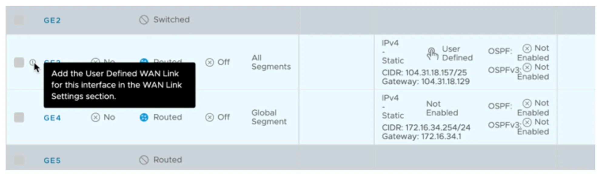
1. Scroll down to **WAN Link Configuration** \> **Add User Defined WAN Link**, and configure the following options:
1. **Link Type**: _Public_ (the WAN interface is connected directly to the Internet in this example — you may need to select _Private_ depending on your environment)
2. **Interfaces**: Check the box for **GE3** (WAN Interface)
2. This example assumes default settings under **View optional** **configuration** and **View advanced settings**.
3. Select **Add Link** to save the changes.
4. Confirm the **User Defined WAN Link** is displayed and an indicator no longer appears next to interface **GE3**.
#### VPN Services
1. Scroll down to **VPN Services**.
2. Expand **Non SD-WAN Destination through Edge** and select the **Override** checkbox.
3. Select **Add**.
4. Select the drop-down under the **Name** column.
5. Select the **Network Service** defined earlier. For example, `Magic_WAN_vc-edge-03`.
6. In the **Action** column, select the **+** button, and configure the following options:
1. **Public WAN Link**: Choose the Public WAN Link (refer to User-Defined WAN Link)
2. **Local Identification Type**: _FQDN_
3. **Local Identification**: Enter the FQDN specified when configuring Cloudflare WAN IPsec tunnels through the Custom FQDN IKE ID API endpoint.
4. **PSK**: Enter the Pre-Shared Key. Ensure you use the same PSK for both Cloudflare WAN IPsec tunnels.
5. **Destination Primary Public IP**: Pre-populated from the Network Service defined earlier.
6. **Destination Secondary Public IP**: Pre-populated from the Network Service defined earlier.
7. Select **Save** to finish defining the IPsec tunnel settings.
8. Scroll down to the bottom of the Edge configuration page, and select **Save Changes** to finalize the Edge device configuration.
## VeloCloud to Cloudflare WAN routing
Configure the **Site Subnets** to facilitate:
* Routing traffic from one Cloudflare WAN site to other Cloudflare WAN sites.
* Ensure Cloudflare WAN IPsec tunnel health checks perform optimally.
1. Go to **Configure** \> **Network Services**.
2. Expand the **Non SD-WAN Destinations through Edge** section.
3. Select the desired non SD-WAN destination, like `Magic_WAN_vc-edge-03`.
### Site Subnets
Configure a minimum of three IPsec tunnels. This example demonstrates two routes for tunnel health checks and two routes for traffic destined for remote sites:
* Cloudflare WAN IPsec tunnel health checks
* Primary VPN Gateway:
* To the respective Cloudflare WAN IPv4 interface address associated with the primary Cloudflare anycast tunnel endpoint IP address
* Routed through the Primary VPN Gateway.
* Secondary VPN Gateway:
* To the respective Cloudflare WAN IPv4 interface address associated with the secondary Cloudflare anycast tunnel endpoint IP address
* Routed through the Secondary VPN Gateway.
* Remote Cloudflare WAN site(s): CIDR blocks to route through Cloudflare WAN
* The LAN interface for vc-edge-03 is:
* 172.16.34.254/24 (subnet address: 172.16.34.0/24).
* This does not need to be specified under Site Subnets as it is local.
* Assume two remote sites, each of which need to be defined as Site Subnets and routed through both the Primary VPN Gateway and Secondary VPN Gateway.
* 172.16.32.0/24
* 172.16.33.0/24
1. Select the **Site Subnets** \> **Add**. Then, select the following configurations for routes:
1. Tunnel Health Check - Primary:
1. 10.252.11.4/32 - Primary VPN Gateway
2. Tunnel Health Check - Secondary:
1. 10.252.11.6/32 - Secondary VPN Gateway
3. Site vc-edge-01:
1. 172.16.32.0/24 - Primary and Secondary VPN Gateways
4. Site vc-edge-02:
1. 172.16.33.0/24 - Primary and Secondary VPN Gateways
2. The **Site Subnets** tab should look like the following when configured as indicated:
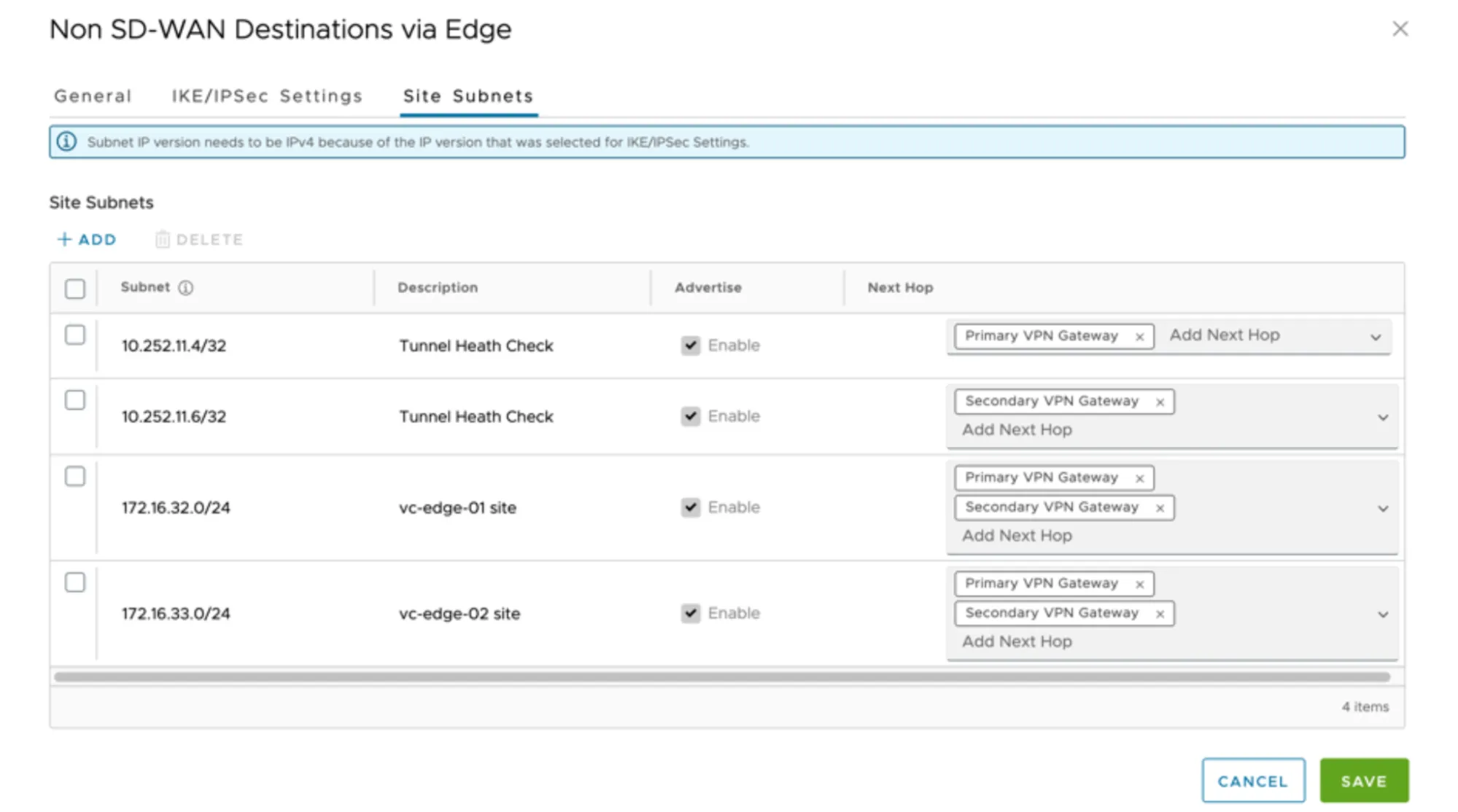
1. Select **Save** to commit changes to the Site Subnets.
## Cloudflare WAN and Cloudflare Gateway
Cloudflare WAN and Secure Web Gateway (Cloudflare Gateway) are tightly integrated. Arista VeloCloud customers can easily route traffic through Cloudflare WAN to Cloudflare Gateway. All Internet egress traffic is subject to Cloudflare Gateway policies.
Arista VeloCloud's Business Policies allow for intelligent routing of traffic destined for the Internet with only a few selections.
### Configure Business Policy
1. Go to **Configure** \> **Edges**, and select the appropriate Edge appliance.
2. Select the **Business Policy** tab.
3. Select **Add** to create a Business Policy Rule:
1. **Rule Name**: Provide a meaningful name to describe Internet traffic routed through the Cloudflare global anycast network.
2. **IP Version**: _IPv4_
3. **Match**
1. **Source**: Select _Any_, _Object Groups_, or _Define_ to classify the relevant traffic flows.
2. **Destination**: Select _Define_ \> _Internet_
3. **Application**: _Any_
4. **Action**
1. **Priority**: Normal
2. **Enable Rate Limit**: Unchecked
3. **Network Service**: _Internet Backhaul_ \> _Non SD-WAN Destination through Edge / Cloud Security Service_.
4. **Non SD-WAN Destination through Edge / Cloud Security Service**: Select the Network Service associated with the respective Edge device. For example, `Magic_WAN_vc-edge-03`.
4. Select **Create** to save the rule.
```json
{"@context":"https://schema.org","@type":"BreadcrumbList","itemListElement":[{"@type":"ListItem","position":1,"item":{"@id":"/directory/","name":"Directory"}},{"@type":"ListItem","position":2,"item":{"@id":"/cloudflare-wan/","name":"Cloudflare WAN"}},{"@type":"ListItem","position":3,"item":{"@id":"/cloudflare-wan/configuration/","name":"Configuration"}},{"@type":"ListItem","position":4,"item":{"@id":"/cloudflare-wan/configuration/manually/","name":"Manual configuration"}},{"@type":"ListItem","position":5,"item":{"@id":"/cloudflare-wan/configuration/manually/third-party/","name":"Third-party integration"}},{"@type":"ListItem","position":6,"item":{"@id":"/cloudflare-wan/configuration/manually/third-party/velocloud/","name":"Velocloud"}}]}
```
---
---
title: Cisco SD-WAN
description: Cloudflare partners with Cisco's SD-WAN solution to provide users with an integrated SASE solution. The Cisco SD-WAN appliances (physical and virtual) manage subnets associated with branch offices and cloud instances. Anycast tunnels are set up between these SD-WAN edge devices and Cloudflare to securely route Internet-bound traffic. This tutorial describes how to configure the Cisco Catalyst 8000 Edge Platforms (physical or virtual) in the SD-WAN mode for north-south (Internet-bound) use cases.
image: https://developers.cloudflare.com/zt-preview.png
---
[Skip to content](#%5Ftop)
Was this helpful?
YesNo
[ Edit page ](https://github.com/cloudflare/cloudflare-docs/edit/production/src/content/docs/cloudflare-wan/configuration/manually/third-party/viptela.mdx) [ Report issue ](https://github.com/cloudflare/cloudflare-docs/issues/new/choose)
Copy page
# Cisco SD-WAN
Cloudflare partners with Cisco's SD-WAN solution to provide users with an integrated SASE solution. The Cisco SD-WAN appliances (physical and virtual) manage subnets associated with branch offices and cloud instances. Anycast tunnels are set up between these SD-WAN edge devices and Cloudflare to securely route Internet-bound traffic. This tutorial describes how to configure the Cisco Catalyst 8000 Edge Platforms (physical or virtual) in the SD-WAN mode for north-south (Internet-bound) use cases.
## Prerequisites
Before setting up a connection between Cisco SD-WAN and Cloudflare, you must have:
* Purchased Cloudflare WAN (formerly Magic WAN) and Secure Web Gateway.
* Cloudflare provisions Cloudflare WAN and Secure Web Gateway.
* Received two Cloudflare tunnel endpoints (anycast IP address) assigned to Cloudflare WAN.
* Cisco SD-WAN appliances (physical or virtual). This ensures specific Internet-bound traffic from the sites' private networks is routed over the anycast GRE tunnels to Secure Web Gateway to enforce a user's specific web access policies.
* A static IP pair to use with the tunnel endpoints. The static IPs should be `/31` addresses separate from the IPs used in the subnet deployment.
* Release 20.6 Controllers and vEdge Device Builds. You should also pair them with devices that are on at least version Cisco IOS XE SD-WAN 17.6\. Refer to [Cisco documentation ↗](https://www.cisco.com/c/en/us/support/docs/routers/sd-wan/215676-cisco-tac-and-bu-recommended-sd-wan-soft.html) to learn more about Cisco software versions.
Note
The SASE integration between Cisco SD-WAN and Cloudflare SSE was validated with Cisco SD-WAN 20.6.2 version with Catalyst 8kv router. For connectivity, we used GRE tunnels.
## 1\. Create a SIG template on Cisco vManage
Cisco vManage is Cisco's SD-WAN management tool that is used to manage all the SD-WAN appliances in branch offices.
For this example scenario, a generic template for `SIG-Branch` was created.
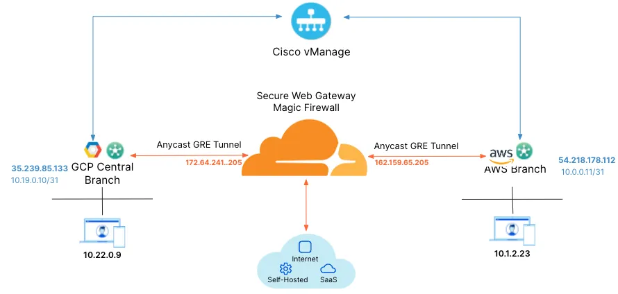
_Note: Labels in this image may reflect a previous product name._
To create a Secure Internet Gateway (SIG) using vManage:
1. From **Cisco vManage** under **Configuration**, select **Generic** and **Add Tunnel**.
2. The table below shows the setting fields and their options.
| Setting | Type/Detail |
| ------------------- | ----------------------------------------- |
| **Global Template** | Factory\_Default\_Global\_CISCO\_Template |
| **Cisco Banner** | Factory\_Default\_Retail\_Banner |
| **Policy** | Branch-Local-Policy |
**Transport & Management VPN settings**
| Setting | Type/Detail |
| --------------------------------- | ----------------------------------- |
| **Cisco VPN 0** | GCP-Branch-VPN0 |
| **Cisco Secure Internet Gateway** | Branch-SIG-GRE-Template |
| **Cisco VPN Interface Ethernet** | GCP-Branch-Public-Internet-TLOC |
| **Cisco VPN Interface Ethernet** | GCP-VPN0-Interface |
| **Cisco VPN 512** | Default\_AWS\_TGW\_CSR\_VPN512\_V01 |
**Basic Information settings**
| Setting | Type/Detail |
| ------------------ | ------------------------------------------- |
| **Cisco System** | Default\_BootStrap\_Cisco\_System\_Template |
| **Cisco Logging** | Default\_Logging\_Cisco\_V01 |
| **Cisco AAA** | AWS-Branch-AAA-Template |
| **Cisco BFD** | Default\_BFD\_Cisco-V01 |
| **Cisco OMP** | Default\_AWS\_TGW\_CSR\_OMP\_IPv46\_... |
| **Cisco Security** | Default\_Security\_Cisco\_V01 |
When creating the Feature Template, you can choose values that apply globally or that are device specific. For example, the **Tunnel Source IP Address**, **Interface Name** and fields from **Update Tunnel** are device specific and should be chosen accordingly.
## 2\. Create tunnels in vManage
From vManage, select **Configuration** \> **Templates**. You should see the newly created template where you will update the device values.
Because the template was created to add GRE tunnels, you only need to update the device values. Note that **VPN0** is the default, and the WAN interface used to build the tunnel must be part of **VPN0**.
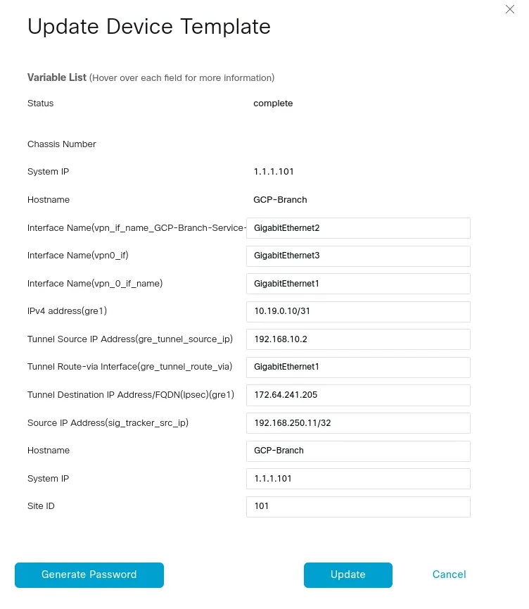
## 3\. Create tunnels in Cloudflare
Refer to [Configure tunnel endpoints](https://developers.cloudflare.com/cloudflare-wan/configuration/manually/how-to/configure-tunnel-endpoints/) for more information on creating a GRE tunnel.
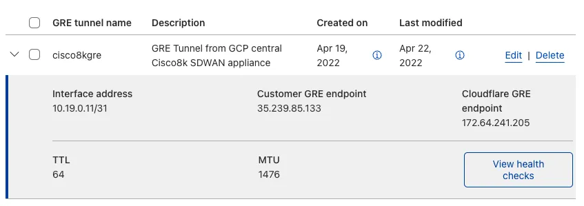
## 4\. Define static routes
Refer to [Configure static routes](https://developers.cloudflare.com/cloudflare-wan/configuration/manually/how-to/configure-routes/#create-a-static-route) for more information on configuring your static routes.
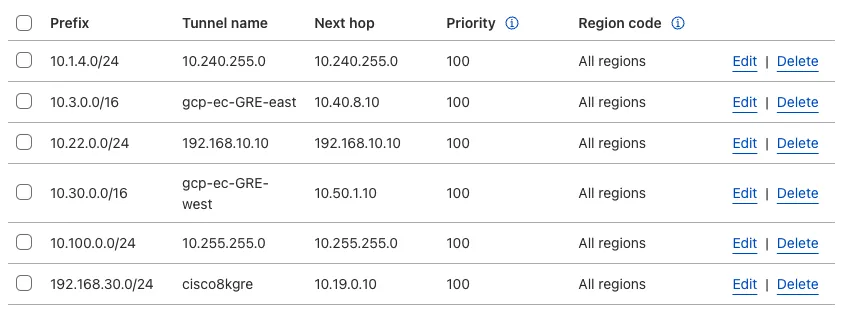
## 5\. Validate traffic flow
In the example below, a request for `neverssl.com` was issued, which has a Cloudflare policy blocking traffic to `neverssl.com`.
On the client VM (192.168.30.3), a blocked response is visible.
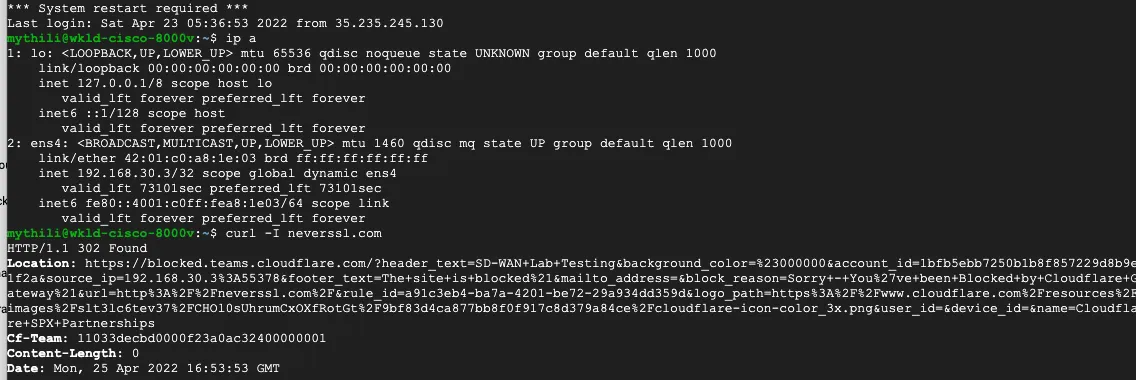
A matching blocked log line is visible from the Cloudflare logs.
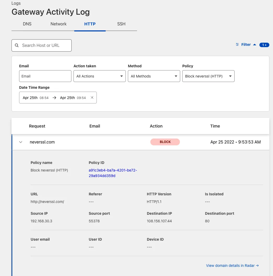
## Add new tunnels using IPsec
IPsec tunnels to Cloudflare can only be created on Cisco 8000v in the router mode today. Refer to the [Cisco IOS XE](https://developers.cloudflare.com/cloudflare-wan/configuration/manually/third-party/cisco-ios-xe/) for more information.
```json
{"@context":"https://schema.org","@type":"BreadcrumbList","itemListElement":[{"@type":"ListItem","position":1,"item":{"@id":"/directory/","name":"Directory"}},{"@type":"ListItem","position":2,"item":{"@id":"/cloudflare-wan/","name":"Cloudflare WAN"}},{"@type":"ListItem","position":3,"item":{"@id":"/cloudflare-wan/configuration/","name":"Configuration"}},{"@type":"ListItem","position":4,"item":{"@id":"/cloudflare-wan/configuration/manually/","name":"Manual configuration"}},{"@type":"ListItem","position":5,"item":{"@id":"/cloudflare-wan/configuration/manually/third-party/","name":"Third-party integration"}},{"@type":"ListItem","position":6,"item":{"@id":"/cloudflare-wan/configuration/manually/third-party/viptela/","name":"Cisco SD-WAN"}}]}
```
---
---
title: VyOS
description: This tutorial provides configuration information and a sample template for using a VyOS device with an IPsec configuration.
image: https://developers.cloudflare.com/zt-preview.png
---
[Skip to content](#%5Ftop)
Was this helpful?
YesNo
[ Edit page ](https://github.com/cloudflare/cloudflare-docs/edit/production/src/content/docs/cloudflare-wan/configuration/manually/third-party/vyos.mdx) [ Report issue ](https://github.com/cloudflare/cloudflare-docs/issues/new/choose)
Copy page
# VyOS
This tutorial provides configuration information and a sample template for using a VyOS device with an IPsec configuration.
## Notes
* `vti ` \- Specifies the virtual tunnel interface of the IPsec tunnel.
* `esp-group ` \- Encrypts traffic through the tunnel using a particular ESP policy or profile.
* `ike-group ` \- Exchanges keys using a particular IKE policy or profile.
* The IP addresses of the IPsec tunnel interfaces on both ends of the tunnel should be a pair of private IP addresses (RFC 1918) on the same `/31` or `/30` subnet, specifying a point-to-point link.
* The IPsec tunnel endpoint on this VyOS router is the ``.
* The IP address of the IPsec tunnel endpoint on the Cloudflare side is one of the anycast IP addresses assigned to your account, available in [Leased IPs ↗](https://dash.cloudflare.com/?to=/:account/ip-addresses/address-space).
* This router is configured to initiate the IPsec tunnel connection.
## Configuration parameters
### Phase 1
* **Encryption**
* AES-GCM with 128-bit or 256-bit key length
* **Integrity**
* SHA512
### Phase 2
* **Encryption**
* AES-GCM with 128-bit or 256-bit key length
* **Integrity**
* SHA512
* **PFS group**
* DH group 20 (348-bit random ECP group)
## Configuration template
Terminal window
```
set interfaces vti address
''
set vpn ipsec esp-group compression 'disable'
set vpn ipsec esp-group lifetime '86400'
set vpn ipsec esp-group mode 'tunnel'
set vpn ipsec esp-group pfs 'enable'
set vpn ipsec esp-group proposal 1 encryption 'aes256gcm128'
set vpn ipsec esp-group proposal 1 hash 'sha512'
set vpn ipsec ike-group close-action 'none'
set vpn ipsec ike-group dead-peer-detection action 'restart'
set vpn ipsec ike-group dead-peer-detection interval '30'
set vpn ipsec ike-group dead-peer-detection timeout '120'
set vpn ipsec ike-group ikev2-reauth 'no'
set vpn ipsec ike-group key-exchange 'ikev2'
set vpn ipsec ike-group lifetime '28800'
set vpn ipsec ike-group mobike 'disable'
set vpn ipsec ike-group proposal 1 dh-group '20'
set vpn ipsec ike-group proposal 1 encryption 'aes256gcm128'
set vpn ipsec ike-group proposal 1 hash 'sha512'
set vpn ipsec ipsec-interfaces interface ''
set vpn ipsec logging log-level '2'
set vpn ipsec options disable-route-autoinstall
set vpn ipsec site-to-site peer authentication id ''
set vpn ipsec site-to-site peer authentication pre-shared-secret ''
set vpn ipsec site-to-site peer authentication remote-id ''
set vpn ipsec site-to-site peer connection-type 'initiate'
set vpn ipsec site-to-site peer ike-group ''
set vpn ipsec site-to-site peer ikev2-reauth 'no'
set vpn ipsec site-to-site peer local-address ''
set vpn ipsec site-to-site peer vti bind ''
set vpn ipsec site-to-site peer vti esp-group ''
```
```json
{"@context":"https://schema.org","@type":"BreadcrumbList","itemListElement":[{"@type":"ListItem","position":1,"item":{"@id":"/directory/","name":"Directory"}},{"@type":"ListItem","position":2,"item":{"@id":"/cloudflare-wan/","name":"Cloudflare WAN"}},{"@type":"ListItem","position":3,"item":{"@id":"/cloudflare-wan/configuration/","name":"Configuration"}},{"@type":"ListItem","position":4,"item":{"@id":"/cloudflare-wan/configuration/manually/","name":"Manual configuration"}},{"@type":"ListItem","position":5,"item":{"@id":"/cloudflare-wan/configuration/manually/third-party/","name":"Third-party integration"}},{"@type":"ListItem","position":6,"item":{"@id":"/cloudflare-wan/configuration/manually/third-party/vyos/","name":"VyOS"}}]}
```
---
---
title: Yamaha RTX Router
description: This tutorial describes how to configure the Yamaha RTX840 and RTX1300 series router to connect to Cloudflare WAN (formerly Magic WAN) via IPsec tunnels.
image: https://developers.cloudflare.com/zt-preview.png
---
[Skip to content](#%5Ftop)
Was this helpful?
YesNo
[ Edit page ](https://github.com/cloudflare/cloudflare-docs/edit/production/src/content/docs/cloudflare-wan/configuration/manually/third-party/yamaha.mdx) [ Report issue ](https://github.com/cloudflare/cloudflare-docs/issues/new/choose)
Copy page
# Yamaha RTX Router
This tutorial describes how to configure the Yamaha RTX840 and RTX1300 series router to connect to Cloudflare WAN (formerly Magic WAN) via IPsec tunnels.
## Testing environment
These configurations were tested on the Yamaha RTX840 and RTX1300 series with the following firmware versions:
* **RTX840 series**: 23.02.02
* **RTX1300 series**: 23.00.17
## Cloudflare WAN configuration
You need to add IPsec tunnels and static routes to your Cloudflare account via the Cloudflare dashboard.
Before proceeding, ensure that you have the anycast IPs assigned to your account. You can find them in the Cloudflare dashboard under **Address Space** \> [**Leased IPs** ↗](https://dash.cloudflare.com/?to=/:account/ip-addresses/address-space).
### IPsec tunnels
1. Follow the [Add tunnels](https://developers.cloudflare.com/cloudflare-wan/configuration/manually/how-to/configure-tunnel-endpoints/#add-tunnels) instructions to create the required IPsec tunnel. When creating your IPsec tunnel, make sure you define the following settings:
* **Tunnel name**: Enter your tunnel name. In this example, it is `RTX840-vpn01`.
* **Interface address**: Enter the internal tunnel IP on the Cloudflare side of the IPsec tunnel. In this example, it is `172.30.223.2/31`.
* **Customer endpoint**: Enter the WAN IP address of your RTX router. In our example, this is `194.xx.xx.xx`. This is the fixed public IPv4 address you get from your ISP for your internet service.
* **Cloudflare endpoint**: One of the Cloudflare anycast IP addresses assigned to your account.
* **Health check rate**: _Medium_.
* **Health check type**: _Request_.
* **Health check direction**: _Bidirectional_.
* **Health check target**: _Default_.
* **Pre-shared key**: Select **Use my own pre-shared key** and paste a secure key of your own.
* **Replay protection**: Do not check the box, to keep this disabled.
2. After you create your tunnel, the Cloudflare dashboard will load a list of tunnels set up for your account. Select the IPsec tunnel you have just created, and check the following setting:
* **FQDN ID**: Copy this ID and save it. You will need it when configuring the IPsec tunnel on your RTX router.
### Static routes
Static routes are required for any networks that will be reached via the IPsec tunnel. In our example, there is one network: `172.16.2.0/24`.
Follow the [Configure static routes](https://developers.cloudflare.com/cloudflare-wan/configuration/manually/how-to/configure-routes/) instructions to create a static route (settings not mentioned here can be left with their default values):
* **Description**: `RTX840-lan01`
* **Prefix**: `172.16.2.0/24`
* **Tunnel/Next hop**: _RTX840-vpn01_
## RTX router configuration
Use the CLI to configure these settings.
### Route settings
```
ip route default gateway tunnel 1
ip route gateway
ip route < ISP's DNS server IP > gateway
```
### LAN settings
```
ip lan1 address 172.16.2.254/24
```
### Wired WAN settings
```
ip lan2 address 194.xx.xx.xx/29
ip lan2 nat descriptor 1000
```
### IPsec VPN main side settings
```
tunnel select 1
ipsec tunnel 1
ipsec sa policy 1 1 esp aes256-cbc sha256-hmac anti-replay-check=off
ipsec ike version 1 2
ipsec ike duration ipsec-sa 1 3600
ipsec ike duration isakmp-sa 1 28800
ipsec ike encryption 1 aes256-cbc
ipsec ike group 1 modp2048
ipsec ike hash 1 sha256
ipsec ike keepalive log 1 off
ipsec ike keepalive use 1 on rfc4306 10 6
ipsec ike local address 1 194.xx.xx.xx
ipsec ike log 1 key-info message-info payload-info
ipsec ike local name 1 fqdn
ipsec ike pfs 1 on
ipsec ike proposal-limitation 1 on
ipsec ike pre-shared-key 1 text
ipsec ike remote address 1